Abstract
Solar cells are popping up on rooftops everywhere these days and are a model for clean, renewable energy. Did you ever look at those solar panels and wonder how we can get electricity produced by solar cells when the sun is not shining? It is a great question because solar panels do not produce electricity when it is dark outside. One strategy to overcome this challenge is to store the energy produced by solar cells during the day in the form of a fuel that can be used at a later time. In this science project, you will explore a cutting-edge method for storing renewable energy by breaking up water molecules into hydrogen and oxygen. The hydrogen and oxygen are fuels that can be burned in devices such as fuel cells to produce clean electricity when it is dark!Summary
Elizabeth R. Young, Ph.D., MIT
Yogesh Surendranath, MIT
Thomas Teets, MIT
Edited by Sandra Slutz, Ph.D. and Teisha Rowland, Ph.D., Science Buddies

Objective
Examine water's usefulness as a renewable energy source by observing how efficient a cobalt-based catalyst can be at helping to form molecular oxygen.
Introduction
The sun is setting on a brisk fall evening, and all of a sudden your TV turns off right in the middle of your favorite show! Without the sun, the solar cells on your roof cannot generate electricity to run your appliances. That is not a good scenario! Many forms of renewable energy, such as solar energy and wind energy, are not available at all times of the day and night. These renewable energies are intermittent sources of energy. We, as a society, however, need energy to be available at all times. For this reason, renewable energy sources like solar energy pose particular challenges to engineers if they are to be used by power plants that generate electrical energy for your house, or for your car in the place of gasoline. Currently, power plants that supply energy to your house run on coal, natural gas, or gasoline as a fuel source and can do so 24 hours a day, 7 days a week. However, these fuels are carbon-based, meaning that they can generate pollutants. Additionally, fossil fuels are unsustainable, meaning that they will eventually run out. Using clean, renewable energy would be a solution to these problems.
Sunlight is a form of renewable energy that is virtually limitless: more solar energy strikes the earth each hour than the entire world uses in a year! However, for solar energy to become practical, we need a cheap and efficient method of storing the solar energy for when the sun does not shine. One method to achieve efficient storage of solar energy is in chemical bonds. Specifically, what scientists and engineers seek to do is use the energy from the sun to rearrange low energy bonds to form high energy bonds. The high energy bonds can be used later to deliver the energy back to us when we need it. This concept is comparable to when you charge a reusable battery. You get electricity from the wall socket, store it in the battery, and when you need to run your phone or computer, the energy is available. To learn more about electricity, check out the Science Buddies Electricity, Magnetism, & Electromagnetism Tutorial.
In fact, society is already familiar with this concept of energy storage in chemical bonds in the form of fossil fuels (like gasoline and natural gas). By burning these fuels, energy contained within those high-energy bonds is released (and used by humans) along with carbon dioxide (CO₂) (which is not used by humans). The bonds between the carbon and oxygen in the carbon dioxide molecules have lower energy than the high energy bonds between the carbon and hydrogen in the fossil fuels. In this instance, the process is irreversible—once the carbon dioxide is created, it is released and cannot be easily converted back to fuel.
A primary goal for renewable energy research is to develop fuel storage methods that are scalable, sustainable, and do not used carbon-based fuels. The ideal energy cycle would be a fully renewable one where the fuels can be utilized (burned to extract the energy from the high-energy bonds) and the waste products (low energy bonds) can be captured and reused to form the same fuel again.
One attractive approach for renewable energy storage is to use solar energy to drive the rearrangement of water (low-energy bonds) into molecular hydrogen gas and oxygen gas (high-energy bonds), as shown in Equation 1 below. This transformation, often called water splitting, provides attractive alternatives to hydrocarbon fuels. The hydrogen and oxygen gas can be stored separately, and later brought together as fuel in what is called a fuel cell. The combustion of hydrogen fuel (which is really the "burning" of hydrogen fuel, H₂, by letting it react with oxygen, O₂) releases water instead of carbon-based molecules, such as carbon dioxide and carbon monoxide. The water that is formed upon combustion of the hydrogen can be collected and "split" again to remake the fuel. In this way, the cycle is sustainable.
Equation 1:- H₂O is water.
- H₂ is molecular hydrogen gas.
- O₂ is molecular oxygen gas
However, achieving efficient "splitting" of water requires a catalyst that assists oxygen-oxygen bond formation between two oxygen atoms derived from water to create oxygen gas. A catalyst is a material or molecule that increases the rate of a reaction between other starting materials, but is not used up in the reaction. Because the catalyst both increases the reaction rate and reduces the energy required to produce the product, the desired product can be made more quickly and with less total energy — is more energy efficient.
Equation 2:Consider the reaction in Equation 2 above. With a catalyst present, we do not need as much energy to make C as we would have needed if the catalyst was absent, and with a catalyst present, we can make C much more quickly. One example to help explain this is to consider that A is a taxi driver and B is a person at the airport. The goal of the "reaction" is to get A and B together so that the taxi driver can take the passenger to a desired location called C. Without a catalyst, both the taxi driver and the person would wander around the airport, requiring a large amount of energy (through walking or driving) and time to bump into each other. However, if there is a taxi stand, acting as the catalyst, the taxi driver and the person would be able to find each faster with less energy wasted.
Going back to Equation 1, as mentioned above, catalysts are needed to efficiently split water because all water-splitting schemes require the inefficient step of producing oxygen. When water-splitting naturally occurs during photosynthesis inside the leaves of plants, chlorophyll acts as a catalyst for this reaction as protons and electrons are extracted from water. Because producing oxygen from splitting water is a barrier to using artificial photosynthesis (the splitting of water into H₂ and O₂ as a renewable energy, many research programs focus on designing catalysts that assist with this oxygen-producing step.
To split water, electrons and protons are removed from water to produce the O₂. The energy needed to drive this reaction is provided by changing the potential energy (or simply potential) of the electrons that are removed. If too high of a potential is used, the extra energy, known as overpotential, which does not get stored in O₂ is wasted as heat and makes the process inefficient. Thus, the goal of research is to reduce the overpotential required while increasing the rate of the reaction.
A catalyst formed from cobalt ions (Co) in a phosphate (Pi) buffered solution (Co-Pi) has recently been discovered, in Dr. Nocera's lab at MIT, that is capable of water oxidation to O₂ at low overpotentials and high rates. The catalyst is comprised of inexpensive, earth-abundant elements, and its formation is robust under a host of conditions. See the video above for more details about the discovery of the Co-Pi catalyst.
In this chemistry and environmental engineering science project, you will construct an experimental set-up that will allow you to synthesize this cutting-edge cobalt-based catalyst. You will perform measurements to determine how much the catalyst reduces the energy needed for the water-splitting reaction to form oxygen. Does it sound too challenging? If you watch the video below you will see that setting up the experiment really is not that hard. Especially if you follow all the steps in the Experimental Procedure! Once you get the hang of it, you can use your set-up to try to discover your own new and improved catalysts! Maybe you will find the one that we will all be using someday to power the planet.
Terms and Concepts
- Renewable energy
- Fossil fuels
- Solar energy
- Low energy bonds
- High energy bonds
- Water splitting
- Fuel cell
- Catalyst
- Potential energy
- Overpotential
- Electroplating
- Electrochemical cell
- Baseline
- Buffer solution
Questions
- What is the key problem with using water splitting as a way of storing energy?
- How much energy does it take to split water? How much energy is retrieved by recombining the molecular hydrogen and oxygen during hydrogen combustion?
- There are many reactions that store about the same amount of energy as water splitting. For example, hydrochloric acid (HCl) can be split into hydrogen (H₂) and chlorine (Cl₂) to store solar energy. What are some of the advantages that water splitting has over alternative energy-storing reactions like HCl splitting?
- Why was cobalt chosen as a possible water splitting catalyst? Based on this information, can you suggest other elements that might also work as a catalyst for this reaction?
Bibliography
These resources will give you more information about catalysts, renewable energy, and water splitting:
- Clark, Jim. (2002). The Effect of Catalysts on Reaction Rates. Retrieved February 18, 2011.
- Witcombe, C. and Hwang, S. (n.d.) The Hydrogen and Oxygen of Water. Retrieved February 18, 2011.
More information about water splitting and the original discovery of the Co-Pi catalyst can be found using these resources:
- Chemical Explorers. (n.d.) Tiny Bubbles. Retrieved February 18, 2011.
- Kanan, M.E., Surendranath, Y., and Nocera, D.G. "Cobalt-phosphate oxygen-evolving compound" Chemical Society Review, 2009, 38, 109-114.
- Kanan, M.W., and Nocera, D.F. "In Situ Formation of an Oxygen-Evolving Catalyst in Neutral Water Containing Phosphate and Co²⁺." Science. 2008, 22, 1072-1075. Retrieved September 28, 2012.
For more information about setting up a circuit on a breadboard, or electronics terms, use this tutorial:
- Science Buddies. (n.d.). How to Use a Breadboard. Retrieved June 23, 2016.
Materials and Equipment
You will need the following materials:
- 9V batteries (4); available at Amazon.com
- 22-gauge electrical wire, 100 ft; available at Jameco
- Alligator clips (12); available at Jameco
- Wire cutters and strippers; available at Jameco
- Breadboard, 3" x 2"; available at Jameco
- 10K Ohm resistor; available at Jameco
- Digital multimeter. See our multimeter tutorial if you do not know how to use a multimeter.
- Jar, plastic, 500 mL (large enough to completely fit the nickel metal strips); available at Amazon
- 250 mL glass beaker; available at Amazon
- Small Styrofoam piece; available at Amazon
- Nickel metal strips (2) (strips are approximately 5 inches tall and ¾ inch wide); available at Amazon
- Metal scoop for chemicals; available at Amazon
- Cobalt nitrate hexahydrate; available at Amazon
- 0.1 M phosphate buffer solution, pH 7.0 (500 mL).
To make this buffer you need following materials:
- Monopotassium phosphate (KH₂PO₄); available at Amazon
- Sodium phosphate dibasic (Na₂HPO₄); available at Amazon
- Deionized water; available at Amazon
- Measuring cup, 500 mL; available at Amazon
- Digital scale with 0.1 g increments; a digital scale that would be suitable is the Fast Weigh Digital Pocket Scale; available from Amazon.com
- To prepare the buffer add both, 2.63 g monopotassium phosphate (KH₂PO₄) (FW 136.09 g/mol) and 4.35 g sodium phosphate (Na₂HPO₄) (FW 141.96 g/mol) into the measuring cup (to lower the pH to 7.0). Then bring it to 500 mL using deionized (DI) water for a total phosphate concentration of 0.1 M. The pH should be around 7.
- Phillips head screwdriver, small; available at Amazon
- Chemical splash goggles; available at Amazon
- Cola; any brand, such as Coke, Pepsi, or a generic brand, will work
- Ruler, metric
- Clock or stopwatch
- Permanent marker
- A helper
- Lab notebook
- Magnetic stir plate and stir bar
- This is a relatively expensive piece of equipment. Many school chemistry labs have stir bars and stir plates. Try borrowing one from school or asking your teacher if you can run this experiment at school using this equipment.
Disclaimer: Science Buddies participates in affiliate programs with Home Science Tools, Amazon.com, Carolina Biological, and Jameco Electronics. Proceeds from the affiliate programs help support Science Buddies, a 501(c)(3) public charity, and keep our resources free for everyone. Our top priority is student learning. If you have any comments (positive or negative) related to purchases you've made for science projects from recommendations on our site, please let us know. Write to us at scibuddy@sciencebuddies.org.
Experimental Procedure
Creating the Galvanostatic Electrochemical Cell
- To start this science fair project, you should assemble the necessary chemicals, electrodes, components, and instruments you need, as specified in the Materials and Equipment list above. Make sure you are familiar with all of the items in the Terms, Concepts, and Questions section above. If you get stuck, or need more detailed explanations, watch the second video in the Introduction by MIT researchers Yogesh Surendranath, Thomas Teets, and Dr. Elizabeth R. Young. It takes you through the project step-by-step.
-
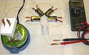
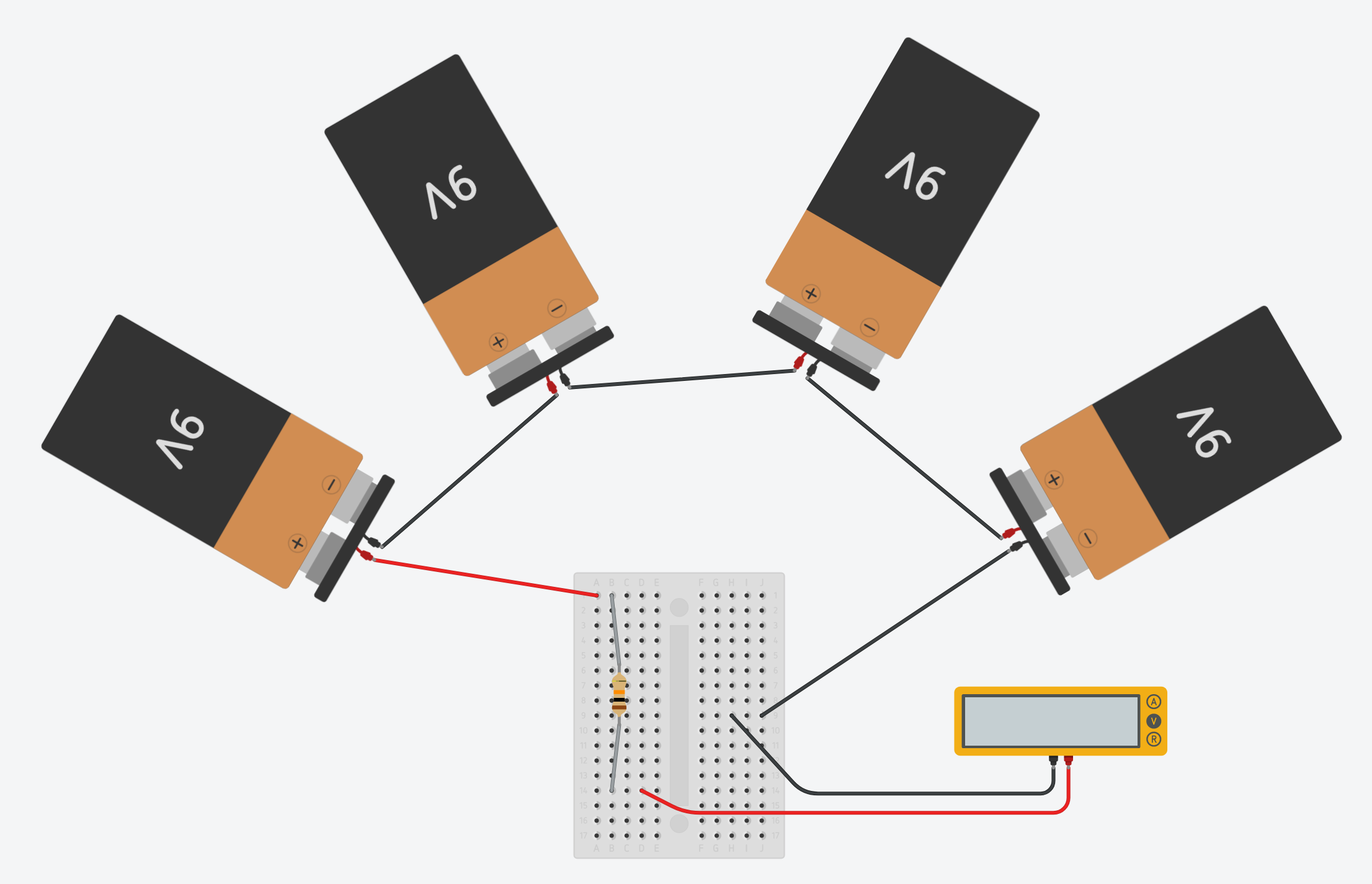
Build a circuit on the breadboard consisting of the batteries, resistor, and voltmeter/multimeter,
as shown in Figures 1 and 2. If you do not have experience building a circuit on a breadboard, see the Science Buddies reference How to Use a Breadboard for Electronics and Circuits. Figure 1 shows you what the completed circuit should look like using two different types of breadboards.
 Image Credit: Teisha Rowland, Science Buddies / Science Buddies
Figure 1. The photos on the top show how the various components in the circuit can be wired onto two different types of breadboard. Below each breadboard photo is a photo of the completed circuit using that type of breadboard, including multimeter leads.
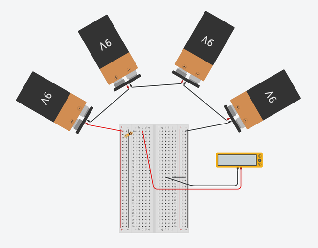 Image Credit: Ben Finio, Science Buddies / Science Buddies
 Image Credit: Ben Finio, Science Buddies / Science Buddies
Figure 2. Breadboard diagrams showing the batteries and multimeter connected to a half-size breadboard (top) and mini breadboard (bottom). Click to open a larger version of the half-size breadboard diagram or mini breadboard diagram. Images made with Tinkercad Circuits.
-
Using Figures 1 and 2 as visual references, connect the four 9V batteries in series using some wire and 6 alligator clips.
- Cut each piece of wire to the desired length with the wire cutters.
- When using wire to attach components in a circuit, the ends of each piece of wire need to be stripped, with the wire stripper, before creating the connection.
- Note: For some alligator clips, the stripped wire will need to be coiled around the alligator clips and then screwed in place. This is shown in Figure 3 below.
- Connect the batteries so that the negative end of one battery is connected to the positive end of the next battery in the series.
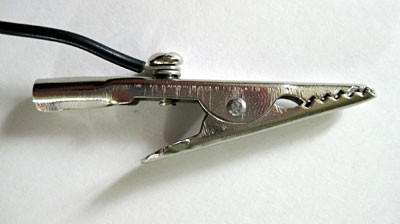 Image Credit: Teisha Rowland, Science Buddies / Science Buddies
Figure 3. If you are using alligator clips similar to these ones, you will need to coil the stripped wire around the alligator clip and then screw the wire in place.
-
Using a piece of wire, connect the positive end of the series of batteries to the breadboard power
bus (far left column, see the Science Buddies reference
How to Use a Breadboard for Electronics and Circuits
if you are confused).
- In Figure 1, for the type of breadboard shown on the left this is the far left "+" column, and for the type of breadboard shown on the right this is the unmarked far left column.
-
Connect the 10K Ohm resistor as shown in Figure 1. (Note: orientation does not matter.)
- For the breadboard shown on the left, one end of the resistor is connected to the same column as the positive end of the batteries, and the other end of the resistor is connected to position 1a.
- For the breadboard shown on the right, one end of the resistor is connected to the same row as the positive end of the batteries, and the other end of the resistor is connected to another position in the same column.
-
Connect the positive (red) lead from the voltmeter/multimeter to the breadboard as shown in Figure 1.
- For both types of breadboards, the voltmeter/multimeter's positive lead is connected to a position in the same row as the end of the resistor (in the breadboard shown on the left, this is position 1c).
-
Connect the negative (black) lead from the voltmeter/multimeter to the breadboard as shown in Figure 1.
- For both types of breadboards, the voltmeter/multimeter's negative lead is connected to a position on the right half of the breadboard. (In the breadboard on the left in Figure 1, position 7h is used.)
-
If you are using the type of breadboard shown on the left in Figure 1, connect a small piece of wire between a position in the same row as the voltmeter/multimeter's negative lead (7j is used in Figure 1) and the ground bus (the far right "-" column).
- If you are using the type of breadboard shown on the right, skip this step.
-
Using a piece of wire, attach the negative (-) end of the series of batteries to the ground bus (far right column) of the breadboard as shown in Figure 1.
- If you are using the type of breadboard shown on the right, make sure this is in the same row as the voltmeter/multimeter's negative lead.
-
Using Figures 1 and 2 as visual references, connect the four 9V batteries in series using some wire and 6 alligator clips.
- The circuit is now complete and should look like the circuit in Figure 1. Using the voltmeter/multimeter, make sure the circuit reads >30V. If you need help using a multimeter, consult the Science Buddies reference How to Use a Multimeter, as well as the instruction manual that came with your voltmeter/multimeter.
-
Use the nickel metal strips as electrodes. The nickel electrodes will serve as the scaffold for
formation or electroplating of the cobalt catalyst.
-
To clean the electrodes (nickel metal strips), pour some cola into a cup or jar. Put both electrodes in the cola. Make sure the nickel is entirely immersed. Cola contains phosphoric acid. This acid will do a great job of cleaning the surface of the electrodes. After a few minutes, remove the nickel electrodes, wash them off with plain water, and dry them.
- If the jar is too small to immerse the electrodes, do the procedure once then flip the electrodes over (putting the end that was not previous immersed in the Cola) and repeat.
- Note: Use the 500 mL jar for this step.
-
Construct a method to secure electrodes within a small beaker or jar that leaves the top of the electrodes readily available to make an electrical connection to the rest of the circuit you started preparing above. An example of a method to secure the electrodes is shown in Figure 4 below using a piece of Styrofoam to hold the electrodes securely in place.
-
It is important to ensure that the separation between the electrodes remains the same throughout the experiment. When securing the electrodes make sure to:
- Position the electrodes 1-2 centimeters (cm) apart.
- Make sure the electrodes are securely in place and not dangling freely or touching the sides of the beaker.
- Position the electrodes so that they will, later, once the buffer has been added to the beaker, only be immersed half way in the buffer. Note: It is critical that the top of the electrodes do not touch the buffer.
- Note: Use the Styrofoam disc and the 250 mL beaker for this step.
-
It is important to ensure that the separation between the electrodes remains the same throughout the experiment. When securing the electrodes make sure to:
-
To clean the electrodes (nickel metal strips), pour some cola into a cup or jar. Put both electrodes in the cola. Make sure the nickel is entirely immersed. Cola contains phosphoric acid. This acid will do a great job of cleaning the surface of the electrodes. After a few minutes, remove the nickel electrodes, wash them off with plain water, and dry them.
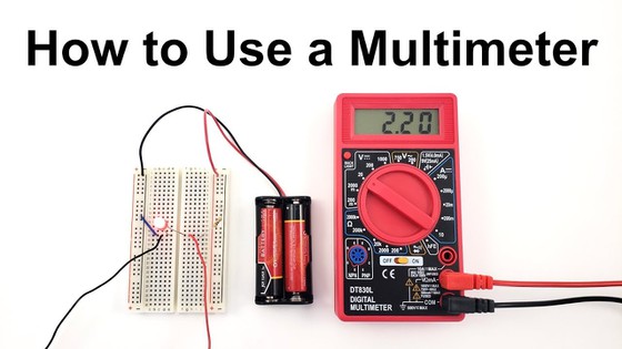
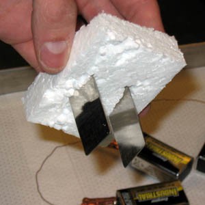 Image Credit: Elizabeth R. Young, Yogesh Surendranath, Thomas Teets / Used with permission
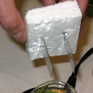 Image Credit: Elizabeth R. Young, Yogesh Surendranath, Thomas Teets / Used with permission
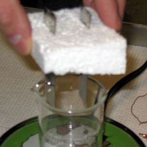 Image Credit: Elizabeth R. Young, Yogesh Surendranath, Thomas Teets / Used with permission
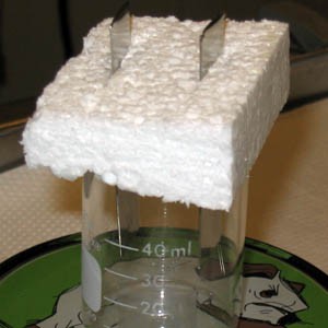 Image Credit: Elizabeth R. Young, Yogesh Surendranath, Thomas Teets / Used with permission
Figure 4. The photos above show one possible method for suspending the nickel electrodes in the beaker to make the electrochemical cell.
-
Add 0.1 M phosphate buffer solution, pH 7.0, to the beaker with electrodes so that the nickel electrodes are submerged half way in the buffer solution.
- Note: If you only have 500 mL of phosphate buffer, the most you should fill the beaker with is 250 mL because in a later step you will need to use this same amount of phosphate buffer again.
-
Place the stir bar in the bottom of the jar.
- Make sure that the electrodes are not so low that they will be bumped by the stir bar. If they are, raise them up until they are not.
-
Connect the nickel electrodes to the rest of the circuit using copper wire and alligator clips as shown below in Figure 5.
-
For both types of breadboards shown, one wire is connected to a position in the same row as the voltmeter/multimeter's positive lead, and the other wire is connected to a position in the same row as the voltmeter/multimeter's negative lead (on the other half of the breadboard).
- For example, for the breadboard shown on the left, one wire is connected to position 1e, and the other wire is connected to position 7f.
-
For both types of breadboards shown, one wire is connected to a position in the same row as the voltmeter/multimeter's positive lead, and the other wire is connected to a position in the same row as the voltmeter/multimeter's negative lead (on the other half of the breadboard).
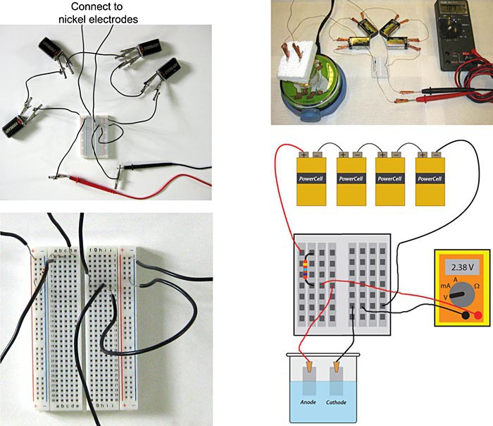 Image Credit: Teisha Rowland, Science Buddies / Science Buddies
Figure 5. The completed galvanostatic electrochemical cell, using two different types of breadboards, is pictured in the top two pictures. One type of breadboard is shown in the left pictures, and a second type is shown in the right pictures. In the top left picture, the leads going up are connected to the nickel electrodes (not pictured). The bottom left picture shows a close-up of the breadboard shown in the top left picture. The bottom right image is a schematic of the completed galvanostatic electrochemical cell pictured in the top right.
Technical Note #1
By following steps 1-7 above you have constructed a simplified galvanostat. This means that the electrochemical cell passes the same current through the cell at all times, and the voltage read-out varies based on the efficiency or property of the electrodes.
The four 9-volt batteries generate a maximum of 36 (9v per battery x 4 batteries in series =36v). You typically will get less than 36 volts depending on how fresh the batteries are. The circuit is completed by two other resistors attached in series. One resistor is the electrochemical cell itself (the nickel electrodes in the phosphate buffer), and the other resistor is a 10,000 Ohm resistor you specifically place in series. This 10,000 Ohm resistor is critical to stabilize the electrochemical cell and ensure that a constant current is passed at all times. The reason for this is that most of the voltage (~30v) drops across the 10,000 Ohm resistor, and approximately 1.5-3v are dropped across the electrochemical cell. It is important to drop most of the voltage through the resistor because this will set the current that passes through the rest of circuit. Small variations in the electrochemical cell will have little effect because the 10,000 Ohm resistor is the dominant factor. Using Equation 3 below, and assuming that approximately 30 volts are dropped over the 10,000 Ohm resistor, the current can be calculated to be 3mA (30v / 10,000 Ohms = 0.003 A = 3mA). This calculation indicates there are 3mA of current flowing through the electrochemical cell.
Equation 3:
- I is current in amperes (A)
- V is voltage in volts (v)
- R is resistance in ohms
Adding the Cobalt Catalyst and Measuring Its Effects
-
With the electrodes securely in place inside the small beaker, place the beaker on the magnetic stir plate. Turn on the stir plate and get the stir bar moving at a constant rate.
- Make sure that the stir bar does not bump the electrodes. Adjust the electrodes if needed, but then keep them in the same position throughout the rest of the experiment.
- Monitor the voltage readout on the voltmeter/multimeter. It should range between 1.9-2.4v and will take at least five minutes to stabilize. After the voltage reading has stabilized, record this voltage in your lab notebook. This is the baseline voltage value for your electrochemical cell.
- Using Equation 4, below, and the information in Technical Note #2, calculate the baseline efficiency of the water splitting reaction in your electrochemical cell.
Technical Note #2
The voltage readout you measure in step 2, above, is the voltage required by the electrochemical cell to maintain a constant current of 3mA (see Technical Note #1 to learn how the current was calculated). This voltage is the sum of the energy required to drive the water-splitting reaction 1.23v + overpotential) and any resistive losses in the cell. If there were no resistive losses, and the water splitting reaction was completely efficient, the necessary voltage to maintain the 3mA current would be 1.23v. From the Introduction, you already know that the water-splitting reaction is not completely efficient and instead has a significant overpotential. In the steps below, you are watching the overpotential drop as the cobalt catalyst is electroplated onto the nickel electrode (specifically, the anode). This drop in overpotential is reflected in a drop in the voltage you measure across the circuit. As the overpotential required by the cell decreases (through addition of the catalyst), the voltage necessary to maintain the 3mA current also decreases. This indicates that you are running the water splitting reaction closer to the absolute, ideal limit. The efficiency of the reaction can be calculated using Equation 4 below.
Equation 4:
If the reaction was 100% efficient, it would require only 1.23v to maintain the 3mA of current passing through the cell. The voltmeter/multimeter would thus read 1.23v. As an example, let us imagine that the initial voltmeter/multimeter reading (in step 2 above) for your electrochemical cell was 2.46v. According to Equation 4, this would mean that without the catalyst, the reaction was 50% efficient (1.23v / 2.46v = 0.50 = 50%). If voltage readings after the addition of the catalyst dropped to 2.12v, then the efficiency would rise to 58% (1.23v / 2.12v = 0.58 = 58%).
-
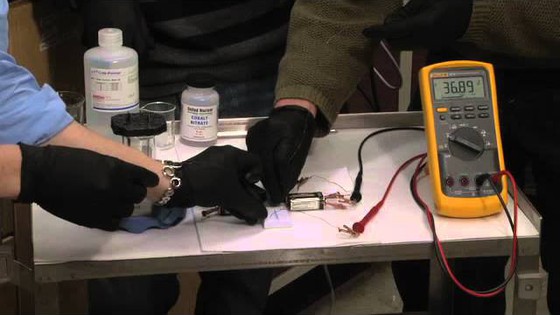
Now it is time to add the reactant necessary to form the cobalt-based catalyst. Put on a pair of disposable gloves and, using the metal scoop, add a pinch of the cobalt nitrate to the jar with the phosphate buffer and either start the stopwatch, or write down the time in your lab notebook. With the cobalt source and the energy provided by the batteries, the catalyst will start to form.
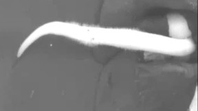
- Adding small amounts of cobalt nitrate each time is critical. The cobalt nitrate concentration must remain very low so the solution does not become cloudy. See Figure 6, below, for a visual reference of how much cobalt nitrate to add at a time.
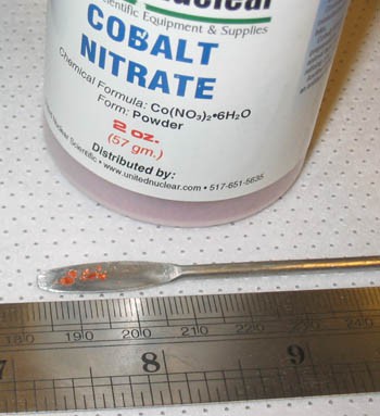 Image Credit: Elizabeth R. Young, Yogesh Surendranath, Thomas Teets / Used with permission
Figure 6. As shown in the picture above, only a small amount of cobalt nitrate should be added to the buffer at a time.
-
The cobalt-based catalyst will begin to electroplate onto the anodic (connected to + side of the battery) nickel electrode. As the catalyst film grows, you will see a brown film growing on the anode, and the voltage readout on the voltmeter/multimeter will slowly drop. Eventually, after several minutes, the voltage will settle to a stable reading. Record this voltage readout. Also record how long it took, using either the stopwatch or clock, to reach a stable voltage reading.
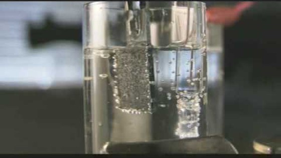
- As the reaction takes place, you will see tiny bubbles forming on the nickel electrodes, similar to those in Figure 7 below.
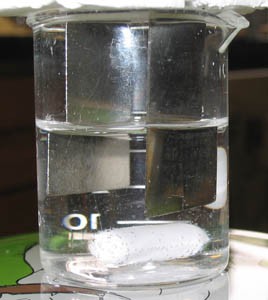 Image Credit: Elizabeth R. Young, Yogesh Surendranath, Thomas Teets / Used with permission
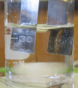 Image Credit: Elizabeth R. Young, Yogesh Surendranath, Thomas Teets / Used with permission
Figure 7. In the beginning, as shown in the photo on the top, there are no bubbles on the nickel electrodes. As the reaction proceeds, the gases formed can be seen as tiny bubbles covering the electrodes, as shown in the photo on the bottom.
-
Once the voltage readout stabilizes, you can add more cobalt nitrate to the solution to
initiate formation of more cobalt-based catalyst. Again, add only a small amount of cobalt nitrate at a time.
- Record in your lab notebook how long it takes the voltage to stabilize again and what that final voltage reading is.
-
Repeat step 6 until the voltage does not appear to change with the addition of more cobalt nitrate. In this instance, the cobalt-based catalyst will continue to work, but no additional catalyst material will form.
- This may take a total of four or five additions of small amounts of cobalt nitrate, and with each addition it may take around 5 to 20 (or more) minutes for the voltage to stabilize.
- As you add more cobalt nitrate, how does the brown film on the anode change? Record any observations in your lab notebook.
- Use a permanent marker to make a mark on the side of the beaker where the phosphate buffer solution level is. Then, have a helper carefully remove the nickel electrodes from the beaker and hold them. While the helper is holding the electrodes, empty the beaker (the phosphate buffer solution can safely be disposed of down the drain), rinse and dry the beaker, and then re-fill it with the same amount of fresh phosphate buffer that was originally in the beaker. This means you will be re-filling the beaker to the mark you just made on it using the permanent marker.
- The solution that the electrodes were in still contained some un-reacted cobalt nitrate, so the electrodes should be transferred to fresh phosphate buffer.
- Note: Be careful that you or your helper does not jostle the electrodes when transferring them to the new solution. It is important that they remain in the same position relative to each other and stay the same distance apart or it could give you inaccurate results.
- At this point you have finished forming the cobalt-based catalyst on the nickel electrodes. Measure and record the stabilized voltage one last time. The voltage readout in pure phosphate buffer reflects the operating potential of the electrochemical cell.
-
Analyze your data.
- Using Equation 4 and the information in Technical Note #2, calculate the final efficiency of the electrochemical cell with the cobalt-catalyst.
- Compare the original efficiency of the cell calculated in step 3 to the final efficiency. How much does the cobalt-based catalyst increase the efficiency of the electrochemical cell?
- How quickly did the cobalt-catalyst form?
- Plot the rate of increase in efficiency for the number of times you repeated step 6. Was the rate of efficiency increase constant?
-
Clean up and disposal.
- The phosphate buffer solution can safely be disposed of down the drain.
- The nickel electrodes can be saved with the cobalt-based catalyst still on them. Or, the nickel electrodes can be recovered and used again by rinsing them in cola as in step 4a, above, of the Creating the Galvanostatic Electrochemical Cell section.
Technical Note #3
Above, we saw that the efficiency of the reaction is determined by the voltage drop across the electrochemical cell. Higher voltages lead to lower efficiency. But what about the speed at which we produce hydrogen and oxygen? Above, we were running our cell at 3mA, and this current is directly proportional to the rate of hydrogen and oxygen production. What if we slow this rate? How would that affect the voltage? Knowing the relationship between the current (rate) and the voltage (energy input) is essential to designing water splitting systems that are practical. As described in Variation 1, change the resistor so that the current is varied between 3mA and 30μA. Plot the cell voltage as a function of the log of the current passed in the cell. Do you get a straight line? What is the slope? Repeat this experiment with catalysts formed for different metal salts (see Variation 2). Plot all of your results on the same graph to determine which catalyst performs the best. Remember that lower voltages and higher currents equal better catalysts.
Troubleshooting
For troubleshooting tips, please read our FAQ: Water to Fuel to Water: The Fuel Cycle of the Future.
Ask an Expert
Global Connections
The United Nations Sustainable Development Goals (UNSDGs) are a blueprint to achieve a better and more sustainable future for all.

Variations
- Consider adding a different resistor to your galvanostatic cell. Based on Technical Note #1, calculate the current that would pass through your cell. Add that resistor. What is the voltage now read by the voltmeter? You should stay within a range of 3mA to 30 μA (i.e. you should only use larger resistors than the 10K Ohms). Using a range of different resistors, you can determine the voltage required to run the electrochemical cell at each current delivered by the galvanostatic circuit. More information about this is provided in Technical Note #3.
- Can the water oxidation catalyst be made from metals other than cobalt? How well do these other metals work? You can purchase different metal salt compounds such as ones containing nickel, iron or manganese and try to add those for the electroplating procedure. You can compare the efficiencies of the electrochemical cells with various metal-based catalysts. How do they compare to the cobalt-based catalyst?
- In the Experimental Procedure, electricity from batteries is used to split water. How would you change the setup to get the energy from sunlight instead of batteries?
Frequently Asked Questions (FAQ)
- Cobalt nitrate can cause skin and eye irritation, and consequently stirring the cobalt nitrate into solution in an open beaker without eye protection can be dangerous.
- For this science project to work correctly, it is very important that the nickel metal electrodes do not get jostled and moved out of position. It can take several minutes of stirring for the cobalt nitrate to completely dissolve and when the electrodes are taken off of the beaker, set aside, and then set back on the beaker, this increases the chance that they will be knocked out of the position they were originally in and affect the results.
- The chemical reactions that happen as the cobalt nitrate dissolves in the buffer could be disrupted by side-reactions that may happen with a stirrer or spoon. (Stir bars are treated so that they should not be reactive.)
- In the circuit with only the batteries, resistor, and voltmeter/multimeter, the voltage should read > 30 Volts (V). If it is less than this, you probably need to use fresher batteries.
- When the circuit is completed (it includes the nickel strip electrodes in the original 0.1 M phosphate buffer solution, pH 7.0), the voltage should then read between 1.9-2.4 V. It may take 20 minutes or more for the reading to stabilize. If your stabilized voltage is not within this range, check the following:
- Make sure everything is hooked up correctly (using Figures 3 to 5 for reference).
- Check that none of the alligator clips or exposed wires are touching each other.
- Make sure that the electrodes are 1-2 centimeters (cm) apart.
- Check that all of the alligator clips and wires are securely attached where they are supposed to be.
- If your voltage is lower than this range, the electrodes may not be sufficiently clean; if they do not look completely clean, put them in a cup or jar again with fresh cola for at least five minutes, making sure they are entirely immersed the whole time.
- After four or five pinches of cobalt nitrate, the voltage should be significantly less, such as around 1.7 V if your original completed circuit reading was 1.9 V. Each time a pinch of cobalt nitrate is added, the voltage should decrease and it may take between 5 to 25 minutes for the voltage reading to stabilize, so some patience is required! If you do not see the voltage decrease after waiting for 15 to 20 minutes, check and do the following:
- Make sure that the stir bar is dissolving the cobalt nitrate. If the stir bar seems to be missing pieces of settled cobalt nitrate, gently move the jar on the stir plate a little so the stir bar is stirring the cobalt nitrate. Be careful not to change the position of the electrodes.
- Try adding a slightly larger pinch of cobalt nitrate.
- When the electrodes are placed in fresh phosphate buffer at the end of the experiment, the voltage should be lower than it was in the original completed circuit, but a little higher than your last reading in the phosphate buffer with cobalt nitrate in it. For example, if your original completed circuit reading was 1.9 V, and it stabilized at 1.7 V after adding several pinches of cobalt nitrate, the reading in fresh phosphate buffer may be around 1.7-1.8 V. It may take at least 10 minutes for this final reading to stabilize. If the voltage in the fresh phosphate buffer at the end of the experiment is not lower than it was in the original completed circuit, check the following:
- Make sure everything is still hooked up correctly and the electrodes have not been knocked out of position.
- Check that the fresh buffer level is not higher than the original buffer level was (or, in other words, make sure the fresh buffer does not go above where the brown film is coating the anode).
- Tip: When you lift up the nickel metal electrodes to add a pinch of cobalt nitrate, do not set the electrodes down as this may knock them out of position. If the electrodes become knocked out of their original position, this can affect your results.
- Connect the positive end of the series of batteries to the power bus (far left) column on the breadboard.
- Connect the resistor so that it will transmit electricity from the power bus to the voltmeter/multimeter's positive lead. How to do this depends on which type of breadboard you have; see Figures 1, 2, and 5 for details.
- Connect the voltmeter/multimeter's positive lead so that it receives the electricity from the resistor. This means that the positive lead will be in the same row as the resistor.
- Connect one of the nickel strip electrodes so that it is also in this row. This will be the anode.
- Connect the other nickel strip electrode so that it will transmit electricity to the other half of the breadboard. This will be the cathode.
- Connect the voltmeter/multimeter's negative lead so that it receives electricity from the cathode. This means that the negative lead will be in the same row as the cathode.
- Depending on the type of breadboard you have (see Figures 1, 2, and 5), you may then need to connect a wire from this row to the ground bus (far right) column on the breadboard. Then connect the negative end of the series of batteries to the ground bus column.
- If you do not need to connect a wire to the ground bus, just connect the negative end of the series of batteries to the far right column, in the same row as the voltmeter/multimeter's negative lead and cathode.
Please refer to the Science Buddies Breadboard Guide for more help on wiring a breadboard.
Careers
If you like this project, you might enjoy exploring these related careers:


Related Links
- Science Fair Project Guide
- Other Ideas Like This
- Chemistry Project Ideas
- Energy & Power Project Ideas
- My Favorites
- Electronics Primer
- How to Use a Breadboard for Electronics and Circuits

