Abstract
Today magnetic recording is used in audio and video cassette recorders, and computer disk drives. Did you know that you can also use an electromagnet to record and play back from a steel wire? In fact, this is how magnetic recording got started. This project shows you how to build a simple wire recorder.Summary
By Jason S. Goldberg, Walter Eppler, and Tim Rauch, Seagate Research, Pittsburgh, PA.
Edited by Andrew Olson, Ph.D., Science Buddies
/-/https/www.sciencebuddies.org/cdn/Files/2395/5/Elec_img015.jpg)
Objective
The goal of this experiment is to learn about magnetic recording heads by building and testing a wire recorder. You'll investigate the relationship between recording current and playback voltage. Other variables to investigate are the number of turns used in the coil for the recording head, and the speed of the moving wire.
Introduction
Magnetic recording has proven to be a quick, safe, and robust method for storing and retrieving information. From the first voice recordings on Poulsen's wire recorder (Figure 1), to the tape recording machines used by radio stations in the 1940's and 1950's that freed the stations from having to produce all of their programs live, to the modern hard disk drive that can store billions of bits of digital information in an area smaller than a quarter, we can see the application of the fundamental principles of magnetism. You can read more about these principles in the Science Buddies Electricity, Magnetism, & Electromagnetism Tutorial.
/-/https/www.sciencebuddies.org/cdn/Files/2395/5/Elec_img015.jpg)
Magnetic materials may be roughly categorized as "hard" or "soft." Magnetically hard materials are able to retain a magnetic moment even after an applied magnetic field is removed. Magnetically soft materials have negligible magnetic moment in the absence of an applied field. Both magnetically hard and magnetically soft materials have a role to play in any magnetic recording system.
At the heart of the recording system is the storage medium, where the signal is stored for later retrieval. This material is necessarily magnetically hard. The choice of material is very important. If the coercivity (Hc) is too high, then it will be difficult to record our signal. If the product of the saturation magnetization (Ms) and the volume (V) is too small, then the replay signal will be small. Additionally, one must worry about the mechanical properties of the storage medium. Corrosive resistance, magnetic grain size, and surface roughness are some examples of important material parameters to measure. Materials must be able to retain their magnetic moments for a reasonable length of time over a suitable range of temperatures and in the presence of stray magnetic fields. The materials chosen for modern tape drives and for disk drives are very different because they have differing requirements for performance and environment.
The magnetic transducer (the recording head) is responsible for writing to the magnetic medium. Reading and writing are two very different processes. However, they are sometimes handled by a single transducer, serving both functions (as will be the case for your wire recorder). Fifteen years ago, a single head both read and wrote in a disk drive. Today there are separate heads for each role. Handling each task with a separate transducer allows engineers to optimize each head for its specific purpose.
The write head needs to convert an electric current into a magnetic field. Ideally, the field generated should be as strong as possible and its strength should fall off as quickly as possible as one moves away from the head. A good basic design for a write head is a coil of wire wrapped around a soft magnetic material. This type of head is known as an inductive head because the coil of wire works as an inductor and generates magnetic flux, which is conducted and concentrated by the soft magnetic material to the pole tip(s). Modern write heads still use this principle. The most classic of head designs is the ring head, wherein the soft magnetic material is in the shape of a toroid (i.e., ring) with a small gap cut into it. The soft material has high permeability and conducts magnetic flux easily, whereas the gap has a low permeability, which causes the magnetic flux to fringe away from the gap area. This fringing field at the gap is used to write to the recording medium.
The read head converts magnetic flux into a voltage potential. It must be sensitive enough to provide a useable signal, and it must respond quickly to changes in magnetic flux. It is possible to use the same head used for writing to read the magnetic fields from the medium. In the reverse of the writing process, magnetic flux is coupled into the soft magnetic core and induces a voltage potential across the coil. In the read configuration, the voltage (v) across the coil is proportional to the change in flux (dφ/dt) experienced by the coil. This is expressed as Faraday's Law:
dt
N is the number of turns in the coil. The negative sign indicates that the voltage is opposite in polarity to the change in magnetic flux. Here, it is important to note that anything that increases the rate of change of the flux will generate a larger output voltage. Often the easiest method for increasing the output voltage is to move the recording medium past the head faster. Increasing the number of turns is also a convenient method for increasing output amplitude.
Currently, hard disk drives use a type of read head that has proven to have much greater sensitivity than the inductive read head. This head operates on the principle known as magnetoresistance. Here, the sensor is a piece of material whose resistance changes in proportion to the magnetic field it experiences. Magnetoresistive heads are not sensitive to the rate of change of the magnetic flux because they sense flux directly.
The Wire Recorder
There are three components to a wire recorder:
- the wire (recording medium),
- the read/write head (and electronics), and
- the mechanics for moving the wire past the head (or the head past the wire).
As you will see when you do this project, each poses its unique challenges!
Pictured is a Telegraphone, the first commercially-produced wire recorder. Your wire recorder will be a greatly simplified version, but will function essentially like the Telegraphone.
/-/https/www.sciencebuddies.org/cdn/Files/2396/5/Elec_img016.jpg)
In a telegraphone a magnetic head moves across a wire that is being pulled between 2 spools. The spools sit on top of a clutch which is powered by motors that can be engaged or disengaged based on which direction the wire needs to move across of the head. Engaging one side will allow for recording, while engaging the opposite side will allow for playback of the recording. The control relay which operates the motors and clutch is electronic and sits in the middle of the machine, it can also be controlled remotely.
Terms and Concepts
To do this project, you should do research that enables you to understand the following terms and concepts:
- transducer,
- Ohm's Law,
- magnetic coil,
- Faraday's Law.
Questions
- What is a magnetic moment?
- For an inductive read/write head, how does the number of turns in the coil affect the playback voltage?
- Why does a magnetic recording medium have to be magnetically "hard?"
Bibliography
- This article, reprinted from The PC Guide, shows you how a modern magnetic recording device—the hard disk drive—works:
Kozierok, C.M., 2005. Hard Disk Drives, StorageReview.com. Retrieved March 24, 2006. - The HyperPhysics site has lots of interesting material related to magnetism. Here are some relevant links:
- Nave, C.R., 2006. Magnetic Dipole Moment, HyperPhysics. Retrieved March 20, 2006.
- Nave, C.R., 2006. Hysteresis in Magnetic Materials, HyperPhysics. Retrieved March 24, 2006.
- Nave, C.R., 2006. Faraday's Law, Hyper Physics. Retrieved March 24, 2006.
- AACG, date unknown. Classification of Magnetic Materials, Applied Alloy Chemistry Group, University of Birmingham. Retrieved March 24, 2006.
Materials and Equipment
To do this experiment you will need the following materials and equipment:
- microphone (e.g., Radio Shack Universal Cassette Recorder Microphone, part #33-3019);
- simple audio amplifier (e.g., Radio Shack Mini Audio Amplifier, part #277-1008);
- mini-phone plug (1/8 in.) for read/write head to amplifier input/output connection (e.g., Radio Shack part #42-2434);
- approx. 6 foot length of hookup wire;
- 2 light duty cart wheels with solid rubber tires, 14 in. diameter (e.g., Grainger.com part #2G344);
- recording wire: solid steel wire or, even better, old magnetic recorder wire (e.g., search eBay category "Consumer Electronics/Vintage Electronics/Other Vintage" for "wire recorder", you should be able to find some for under $10);
- at least 5 ferrite bead cores, more if you want to experiment with the number of turns on the coil. For example, part # 495-3847-ND from Digi-Key. Other ferrite beads with similar dimensions (10.00mm O.D. x 6.00mm I.D. x 4.00mm L) should work too;
- magnet wire, 34 AWG, Belden 8057 or similar (e.g., Newark.com part #36F1320);
- Teflon (or similar smooth, hard plastic) cylinder for wire guide;
- assorted nuts, bolts, washers, lumber, and clamps for attaching wheels (see photographs in Experimental Procedure section);
- digital multimeter;
- heat shrink tubing;
- tape;
- wire cutters;
- super glue (cyanoacrylate);
- emery board or sandpaper;
- soldering iron (or wire clips); and
- small permanent magnets.
Disclaimer: Science Buddies participates in affiliate programs with Home Science Tools®, Amazon.com, Carolina Biological, and Jameco Electronics. Proceeds from the affiliate programs help support Science Buddies, a 501(c)(3) public charity, and keep our resources free for everyone. Our top priority is student learning. If you have any comments (positive or negative) related to purchases you've made for science projects from recommendations on our site, please let us know. Write to us at [email protected].
Experimental Procedure
Wire Recording Media
As was mentioned in the Introduction, a key property of the wire recording media is that it be magnetically "hard." Piano wire can be used, but will produce a low-fidelity recording. (For voice recording, everything sounds like "waw waw waaaw wa", which is obviously no good unless you're trying to sound like an adult in a Charlie Brown cartoon.)
The best solution is to look for a spool of wire specifically made for the old wire recording machines of the 1940's and 1950's. You can probably find this at vintage electronics flea market, or from an online auction site, such as eBay. We recommend trying to find some of this type of wire so that you have at least one wire type that you know should work.
See the Variations section for an idea on exploring various recording media.
Fabricating the Read/Write Head
Safety Note: Remember to wear eye protection while cutting the ferrite bead cores!
-
As described in the Introduction, the recording head is made by wrapping a coil of magnet wire around a magnetically soft core, with a gap cut into it (see Figure 3).
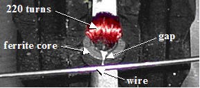
Wire is wrapped tightly around a core and rests upon an iron head. A small gap in the iron head allows magnetic forces to escape from the wrapped wire to the magnetic wire that runs in front of the head.
Figure 3. Close-up of the read/write head. -
The ferrite beads come as solid rings, so you will first have to cut the gap for the recording head. Ferrite is a ceramic material, so cutting the gap is tricky. We can suggest two methods: 1) using a diamond cutting wheel on a motorized tool (e.g., Dremel), or 2) cutting the ferrite with wire cutters and using super glue to put the pieces back together. Each method is described. Be sure to use eye protection no matter which method you use!
- If you have a Dremel tool and are willing to spend about $30 for a diamond cutting wheel, this method is probably the best. The ferrite should be securely clamped while cutting (use padding so that the ferrite is not crushed).
-
The second method uses tape, sharp wire cutters and super glue.
- Wrap the ferrite core in a little bit of tape just to hold the pieces together.
- Using the wire cutters, "cut" through the ferrite bead. Since the ferrite material is brittle, you will end up shattering the bead into three or four large pieces.
- The pieces are held in place by the tape, so it is relatively simple to reassemble them with super glue. Glue the pieces together in such a manner as to leave a small gap.
- Using an emery board, polish the edges of the gap.
- Note that this is a trial-and-error process, and you may have to break four or five cores before you get a nice clean break for the gap.
- Use the magnet wire to wrap a coil around the ferrite core, on the side opposite the gap (see Figure 3). A coil of 200–300 turns should work well, but this could be a variable to explore. Remember that both ends of the coil wire need to be connected for the coil to work, so leave a length of wire sticking out when you start winding.
-
The coil will be connected to the amplifier output when recording, and to the amplifier input for playback. Here's how to make a cable to connect the coil to the amplifier.
- Carefully strip off about 1/4 inch of insulation from each end of the coil wire.
- Cut your hookup wire into two 3-foot lengths and strip off insulation at each end.
- Solder one piece of hookup wire to one end of the coil and the other piece of hookup wire to the other end of the coil.
- Solder the other ends of the hookup wire to the connectors of the mini phone plug.
/-/https/www.sciencebuddies.org/cdn/Files/2397/3/Elec_img017.jpg)
Mechanics
Figure 4, shows a simple transport sytem for moving the wire past the read/write head.
/-/https/www.sciencebuddies.org/cdn/Files/2398/3/Elec_img018.jpg)
- Two wheels are set up horizontally (as shown in Figure 4) to provide a method for moving the recording wire past the read/write head.
- The wheels are 14 inches in diameter because heavier gauge, magnetically hard wires tend to break if bent at too sharp an angle. (For thinner diameter wire, such as wire for antique wire recorders, smaller diameter wheels could be substituted.)
- The wheels have solid rubber tires, which were grooved by hand to a depth of several millimeters. This groove carries the wire.
- The wheels are secured to separate pieces of 2 x 4" lumber to allow the wire to be tensioned between them. The lumber pieces are clamped to the table.
- The wheels spin on threaded bolts which act as axles and allow the wheels to be secured with washers and nuts.
-
A piece of Teflon cylinder is used as a further tensioner and guide for the wire. The Teflon is grooved at a similar height to the tires and the head is placed next to the tensioner. The groove in the Teflon acts as a fixed height surface for the wire to run on despite the (sometimes pronounced) wobble of the inexpensive wheels.
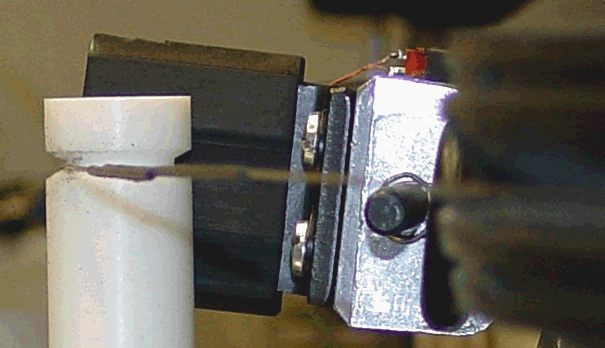 Figure 5. Mechanics: detail of Teflon tensioner device. Also shows splice in heavy gauge wire.
 -
The ends of the wire need to be closed to form a loop.
- For the wire recorder wire, due to its extremely thin diameter, we simply knot the wire ends together. Use a square knot—as any Boy Scout can tell you, hold the wire ends in each hand and then "left over right, right over left" to tie a square knot. Pull the wire to tighten the knot.
- If you are using heavier gauge wire which you cannot tie in a knot, the wire must be spliced. You can accomplish this by overlapping the wire ends, applying super glue, bonding the two ends by applying pressure to the joint, and sealing the joint with suitably sized heat shrink tubing. This results in a joint that has twice the width of the wire and rubs when it passes by the head and Teflon tensioner (see Figure 5). Careful with super glue which bonds skin easily!
- The wire is looped around the wheels (in the grooves made in the tires), and the wheels are spread apart on the table to tension the wire.
- The wheel assemblies are clamped to the table and the Teflon tensioner is placed against the wire, midway between the wheels.
- The read/write head is placed against the wire, as shown in Figure 6.
/-/https/www.sciencebuddies.org/cdn/Files/2399/3/Elec_img019.jpg)
/-/https/www.sciencebuddies.org/cdn/Files/2400/3/Elec_img020.jpg)
Recording and Playback
To record, follow these steps:
- Erase any previous recording on the wire with a permanent magnet (hold the magnet in contact with the wire, and rotate the wheels to slide the wire past the magnet).
- Connect the microphone to the input of the Radio Shack speaker/amplifier.
- Connect the output of the amplifier to the coil on the read/write head.
- Spin the wheels at a constant speed and speak into the microphone. You will have to experiment with the volume control of the amplifier to get the correct input signal strength (see the next section). You can also experiment with the speed of rotation of the wheels.
To play back your recording, follow these steps:
- Connect the head to the amplifier input.
- Rotate the wheels to move the wire past the head.
Experiments
Investigate the relationship between input current and replay voltage.
- Use the digital multimeter to measure the output of the amplifier for a constant-intensity input (e.g., you could hum into the microphone, or you could connect a portable music player to the amplifier and use a suitable portion of a song). Use AC mode, and take an "average" reading. If you need help using a multimeter, check out the Science Buddies resource How to Use a Multimeter.
- Use the digital multimeter to measure the resistance of the coil on the read/write head.
- Use Ohm's law to calculate the recording current (voltage/resistance).
- Record the signal on the wire.
- Use the digital multimeter to measure the voltage of the coil on the read/write head during playback.
- Write down each measurement in your lab notebook.
- Repeat steps 1–6 for at least four different input currents. The easiest way to change the current is by adjusting the volume knob on the amplifier. Keep the input signal to the amplifier constant for all tests.
- Graph the relationship between coil input current during recording and coil output voltage during playback.
- What happens to output voltage when the playback speed is changed? (Refer to the equation for Faraday's Law in the Introduction.) Do you notice any other changes in the output when the playback speed changes? Can you explain them?
/-/https/i.ytimg.com/vi/ts0EVc9vXcs/maxresdefault.jpg)
Ask an Expert
Variations
- Try changing the speed at which you record and play back the signal. Which speed sounds best?
- Try exploring different recording media, e.g., different wire types, or magnetic tape from a recording cassette. What materials are magnetically "hard" enough to hold a recording?
- Try changing the position of the read/write head relative to the wire. Where do you get the best signal? Where is the magnetic force strongest?
- Experiment with the construction of the read/write head. How does performance change with number of turns for wrapping the coil? How does performance change with gap width?
- Can you improve the mechanics of your system? For constant recording speed with a simple system, is it better to have the recording media moving with respect to the head or the recording head moving with respect to the recording media?
- Advanced. If you have a function generator and an oscilloscope, you can test the frequency response of your system by recording and playing back sine waves. Over what frequency range can you record with reasonable fidelity? What happens to the signal as frequency increases beyond this range? Why do you think this happens? What happens when playback speed is different than recording speed? Using the oscilloscope to display the output, can you record and play back a digital signal? How many bytes of data can you record on your wire?
Careers
If you like this project, you might enjoy exploring these related careers:
/-/https/careerdiscovery.sciencebuddies.org/cdn/Files/1801/18/pexels-photo-4988130.jpg)
/-/https/careerdiscovery.sciencebuddies.org/cdn/Files/1223/17/iStock-971549326.jpg)
/-/https/careerdiscovery.sciencebuddies.org/cdn/Files/1242/20/iStock-113511101.jpg)
/-/https/careerdiscovery.sciencebuddies.org/cdn/Files/20162/5/SemiconductorProcessorHeroImage.jpg)

/-/https/img.youtube.com/vi/rzEYT7V-yUk/0.jpg)
/-/https/img.youtube.com/vi/cd04o5yqSAU/0.jpg)
/-/https/img.youtube.com/vi/I7MrL5Q7zvY/0.jpg)