Abstract
If you have ever built an electronic circuit with a soldering iron, you know that the component leads get hot. How much of that heat gets into the device you're soldering? This project shows you how you can use a silicon diode as a temperature sensor to find out.Summary
Written by Charlie Zhai and Richard Blish, Ph.D. ![]()
Edited by Andrew Olson, Ph.D., Science Buddies
Objective
When one solders an electronic component into a circuit, certainly some heat from the gun, pencil, or solder wave must reach into the semiconductor device. How much and how fast? How long would it take for a semiconductor device to reach a dangerously high temperature, say 200°C?
Introduction
Diodes are semiconductor devices that normally allow current to flow in one direction but not the other. When a diode is supplied with a constant current in the forward direction, the voltage across the diode will be proportional to the diode's temperature (more on this below). In this project, you'll learn how to make a constant current source, how to calibrate the diode's voltage readings to temperature, and how you can then use a voltage reading to measure the temperature of the diode when a soldering iron is applied to the lead.
Real-World Applications
Thermal diodes as just described are used extensively in microprocessors to detect excessive temperature, which would be harmful to the device. Excessive temperature can impair reliability or perhaps cause a microprocessor to fail permanently. Excessive temperature also slows charge transport. If the logic "gates" don't achieve their proper state by the time the clock moves to the next "tick," then incorrect data would be present. To avoid creating erroneous data, microprocessors have logic schemes to reduce the applied voltage and/or clock rate to reduce power dissipation (and heat) so that these errors don't occur.
CMOS integrated circuit inputs always have a diode in parallel. Under normal operation the diode is reverse-biased so no current would be flowing. If a spark (either polarity) jumped to the pin corresponding to the input, the diode would conduct. If the spark polarity is negative, the diode conducts in its forward direction; if the spark polarity is positive the peak inverse voltage is exceeded and the diode breaks down. In either case the diode acts as a protective element for the sensitive input gate.
How Diodes Work
Figure 1, below, shows the current-voltage relationship for a typical PN rectifier diode (Wikipedia contributors, 2006). Let's take a few minutes to study and understand this graph.
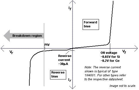
Example graph showing current along the y-axis and voltage along the x-axis which both extend to positive and negative sides. The graph resembles a cubic function and crosses the center axis at (0,0). On the positive side of the graph there is a ON voltage marker where any marginal increase in voltage will lead to a drastic increase in current. On the negative side of the graph there is a peak inverse voltage (PIV) marker where any further decrease in voltage will lead to a drastic decrease in current. The area between the PIV and ON markers is slightly positive and relatively linear.
Figure 1. Current-voltage relationship for a typical PN rectifier diode, type 1N4001 (Wikipedia contributors, 2006).
The graph shows the current through the diode (y-axis) as a function of voltage (x-axis). Let's look at the forward bias region of the graph first. The diode is forward biased when V > 0. In the graph you can see that there is an abrupt change in the slope of the curve when the voltage reaches about 0.7 V (for a silicon-based diode). Above this voltage, the current increases rapidly with voltage. The diode is essentially acting as a switch. Above 0.7 V, the diode is switched on, allowing current to flow with little resistance. Below 0.7 V, the diode is switched off, presenting a large resistance to current.
Now let's look at the reverse bias region of the graph. The diode is reverse biased when V < 0. The first thing you need to know is that the scales of the axes in the reverse-bias region are not the same as the scales used in the forward-bias region. The reverse current is on the order of 30 μA, which is more than three orders of magnitude lower than the 50 mA of forward current at +0.7 V. The peak inverse voltage (PIV) is at least 50 V, compared to the on voltage of 0.7 V. (There is a family of rectifier diodes, numbered 1N4001–1N4007. The PIV increases from 50 to 1000 V as the model number increases.) If the peak inverse voltage is exceeded, the diode will be permanently damaged, and a large negative current flows. But as long as the voltage remains within the operating range for which the diode was designed, the diode acts as an electronic switch, allowing current to flow when the voltage is positive, and blocking current when the voltage is negative.
Now that you understand the basics of how a diode behaves in a circuit, let's take a closer look at the forward-bias region, and see how diodes can be used as temperature sensors. The Shockley ideal diode equation describes the current-voltage relationship of a PN semiconductor diode in the forward bias condition. (Don't let the equation put you off. If you understand exponents, you should be able to follow along.) Here's the equation:
I = Is × [exp(qV/nkT) - 1],
- I is the diode current,
- Is is a scale factor called the saturating current, in Amperes,
- q is the charge on the electron (1.6 10-19 coulombs), but just use 1 electron for this application as we have provided Boltzmann's constant (below) in units of electron volts,
- V is the applied voltage, in Volts,
- n is the emission coefficient, usually with a value ~1, but possibly as large as 2,
- k is Boltzmann's constant, 8.62 10-5 eV/°K,
- T is the absolute temperature of the diode, (remember that °K = °C + 273).
The Shockley equation says that current through the diode increases exponentially with voltage. At room temperature (20°C or 293°K), the exponent (qV/nkT) will equal 1 when V is equal to 25 mV. This value is called the thermal voltage, and it corresponds to the mean thermal energy for any atom or molecule at room temperature. For voltages ≥ 75 mV, exp(qV/nkT) >> 1, so the equation can be simplified to (resulting error is 5% or less):
I = Is × exp(qV/kT).
The simplified Shockley equation tells us that every time the forward bias voltage increases by 25 mV, the forward current increases by a factor of e, the base for the natural logarithms (about 2.718).
If one takes the natural logarithm of both sides of the simplified version for the Shockley equation for forward bias, one gets:
ln(I/Is) = qV/nkT.
If I is made constant by driving the diode from a constant current generator, then the left side of the equation is constant. Clearly equality means the right side would be constant as well. In order for the right side to remain constant, then voltage and absolute temperature must track one another. Thus, a forward-biased diode will act as a thermometer under constant current conditions. The rate of change for voltage vs. temperature is usually in the range 2–3 mV/°K and varies according to the value of the emission coefficient. Since the sensitivity factor (voltage vs. temperature) does vary from one diode to another, one needs to perform a calibration.
A convenient way to calibrate a diode is to measure forward voltage drop at constant current as a function of temperature in a conventional kitchen oven (see the Experimental Procedure section, below).
How does one create an inexpensive constant current source? It's really quite easy! Just take a 9 V battery and a 1 MΩ resistor in series with the "load," the forward-biased diode for our case. Clearly one can use Ohm's Law to see that 9 μA will flow in the loop if the "load" has a resistance much less than the 1 M ohm series resistor. In fact, the characteristic resistance of a forward-biased diode is on the order of 10 kΩ, but keep in mind that this resistance value is strongly dependent on temperature and voltage since a diode is a non-linear device.
Terms and Concepts
To do this project, you should do research that enables you to understand the following terms and concepts:
- Ohm's law,
- diode,
- current-voltage relationship for a diode,
- constant current source.
Questions
- What does it mean to say that a diode is "forward-biased"?
Bibliography
- This Wikipedia article explains the current vs. voltage relationship for a diode:
Wikipedia contributors, 2006. Diode, Wikipedia, The Free Encyclopedia. Retrieved June 1, 2006. - You will find links to technical information on 1N4100x diodes from many manufacturers on the following webpage (all will have similar specifications):
www.DataSheetCatalog.com, 2006. 1N4005 Datasheet pdf, www.DataSheetCatalog.com. Retrieved June 1, 2006.
Materials and Equipment
To do this experiment you will need the following materials and equipment, mostly available from Jameco Electronics:
- 1N4001 diodes (10), part #35975
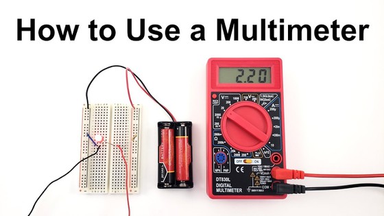
- Digital multimeter. See our multimeter tutorial if you do not know how to use a multimeter.
- 9 V battery, part #198731
- 9 V battery clip, part #1949488
- 1 MΩ resistor (10), part #691585
- Short lengths of hookup wire
- You can buy a single jumper wire kit, for example part #2127718
- If you plan on doing more electronics projects in the future, it is more cost-effective to buy a spool of 22-gauge hookup wire and a pair of wire strippers
- Soldering iron. Multiple soldering irons at different price points are available from Jameco Electronics. If you plan on doing lots of electronics projects, it might be worth investing in a slightly more expensive soldering iron.
- Lead-free solder, multiple options available from Jameco Electronics
- "third hand" for holding diode while soldering (this can be a vise, a soldering tool with clips, or a helper with a pair of long-nose pliers). Several options are available from Jameco Electronics
- Wire ties
- kitchen oven
- thermometer
- timer or stopwatch
Experimental Procedure
-
Do your background research so that you are knowledgeable about the terms, concepts, and questions above.
Calibrating Your Diodes
-
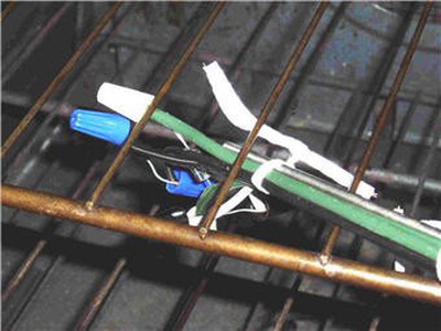
To calibrate a diode, you will connect it to a constant current source, and then measure the voltage drop across the diode as you gradually raise the temperature of the diode (in the kitchen oven). You will need to repeat the calibration for each of your diodes (you should test at least three). Figure 2, below, shows the setup.
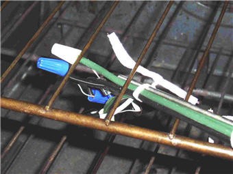
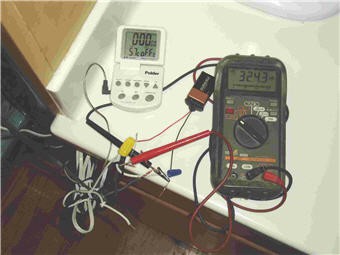
Figure 2. Experimental setup for diode voltage vs. temperature calibration. The first image is a detail view showing diode and temperature probe lashed together and attached to oven rack with wire ties. The constant current source is connected to the diode leads with wire nuts. The second image is the part of the setup that stays outside the oven: temperature probe readout, constant current source (9 V battery and 1 MΩ resistor), and digital multimeter.
- Connect the red (+) lead from the battery clip to the 1 MΩ resistor, then connect the other end of the resistor to the cathode of the diode (lead nearest the stripe). Connect the anode of the diode (lead furthest from stripe) to the black (−) lead from the battery clip.
- Connect the leads from the multimeter to the diode leads (same polarity as for the battery connections). If you need help using a multimeter, check out the Science Buddies reference How to Use a Multimeter.
- As shown in Figure 2, make the leads into a neat bundle with wire ties, and attach the temperature probe. Hang the bundle from the oven rack with wire ties. (Obviously you should do this before turning on the oven!)
- Gently close the oven door.
- Check to make sure all of your connections are solid, and that you are getting good voltage and temperature readings.
- Turn on the oven to low heat. You don't want to go above 75°C (about 170°F), since the wire insulation will start to melt and make a mess. The oven will heat up gradually, so you can take voltage and temperature readings as it does. If you take data every 4 or 5 degrees Celsius, you'll get a good calibration curve.
- Allow the oven to cool and repeat the calibration for several diodes (at least three). Label each diode with permanent marker so that you know which is which.
-
Make a graph of your data like the one shown in Figure 3 (either by hand or with a spreadsheet or graphing program). Then fit a line through the data points (by eye if graphing by hand).

Example scatter plot showing three different diodes with voltage drop on the y-axis, and temperature on the x-axis. For all three diodes the voltage decreases as the temperature increases. A best-fit line is drawn for each set of data, and all the lines have nearly identical decreasing slopes.
Figure 3. Example graph of voltage vs. temperature for silicon diodes at constant temperature.
-
To fit regression lines in Excel, click on the data series, then click on Add Trendline. Choose linear, click the Options tab, and click the check boxes to show the equation and the correlation coefficient. We recommend you color-code trend lines and equations to their respective data.
Measuring Temperature with a Calibrated Diode
- Now that you have each of your diodes calibrated, you can see how quickly they heat up when you simulate soldering them in to a circuit.
- Again you will connect your constant current source and the digital multimeter (as in steps 3 and 4, above). This time you will need to be sure to leave the diode leads accessible so that you can touch the soldering iron to them without touching the multimeter leads or current source wires.
- Heat up your soldering iron, then touch the tip to one of the diode leads for one second. Remove the iron and immediately note the voltage reading. Record it in your lab notebook.
- Let the diode cool down again (check the voltage reading), and then repeat the one-second heating at least twice more, recording the voltage each time.
- What temperature does it correspond to?
- Repeat the heating operation, gradually increasing the time that the soldering iron remains in contact with the diode lead. Take multiple measurements (at least 3) for each time point.
- How long does it take for the diode to reach 200°C?
- Average the readings at each time point and make a graph of diode temperature vs. soldering iron contact time.
Ask an Expert
Global Connections
The United Nations Sustainable Development Goals (UNSDGs) are a blueprint to achieve a better and more sustainable future for all.

Variations
- Does it make a difference where on the lead you apply the soldering iron (i.e., closer to or further from the diode itself)? Why or why not?
- Does it make a difference which diode lead (anode or cathode) is heated with the soldering iron? Why or why not?
- To reduce the amount of heating to a component during soldering, you can place a "heat sink" on the lead, between the component and the tip of the soldering iron (if there is room, of course). The heat sink can be as simple as an alligator clip. Try using a heat sink on the diode lead. Does it work?
- A soldering iron transfers heat much more efficiently when the tip is tinned with molten solder than when the tip is dry. Can you use your setup to produce evidence that this is true?
Careers
If you like this project, you might enjoy exploring these related careers:


Related Links
- Science Fair Project Guide
- Other Ideas Like This
- Electricity & Electronics Project Ideas
- My Favorites