Abstract
You can see examples of parabolic reflectors in flashlights, car headlights, satellite TV antennas, and even on the sidelines at football games. How do these "dish" antennas work to gather signals? What is the best position for placing the detector for these antennas? In this project, you can use an LED and a simple photodetector to find out for yourself.Summary
/-/https/www.sciencebuddies.org/cdn/Files/2899/3/CompSci_img011.gif)
Objective
The goal of this project is to determine the best position of a parabolic reflector for sending and receiving signals with light.Introduction
Parabolic reflectors are used in many applications, including: flashlights, optical telescopes, radio telescopes, solar ovens, and even for picking up on-field sounds from the sidelines at football games. What is so special about the parabaloid shape that makes it useful in so many applications?
A parabola is a two-dimensional curve consisting of the points that are equidistant from a point (called the focus) and a line (called the directrix). Figure 1 (Weisstein, 1999) illustrates the essentials. The left half of the figure shows the directrix, the vertex, and the focus of the parabola. The vertex is at the origin, (0, 0). The directrix (L) is the vertical line with x-coordinate −a. The focus, F is thus at the point (a,0). The right half of the figure shows graphically that the points of the parabolic curve are equidistant from L and F.
/-/https/www.sciencebuddies.org/cdn/Files/2899/3/CompSci_img011.gif)
A parabola is drawn next to a vertical line labeled the directrix. The closest point to the directrix on the parabola is the vertex and a focal point is located opposite the directrix line at the same distance from the directrix line to the vertex. All points on a parabola are shown to be equidistant from the focus point and the directrix line.
Figure 1. Diagram of a parabola, showing, on the left, the directrix, vertex and focus, and, on the right, illustrating that each point on the parabola is equidistant from the directrix, L, and focus, F.
The right half of Figure 1 also implies a property that makes the parabolic shape so useful in the reflector applications mentioned previously. The property is this: waves from a point source placed at the focus, F, are reflected by the parabolic curve as waves traveling parallel to the parabola's axis of symmetry (the line y = 0). So the parabolic curve is useful in flashlights because it directs the light in a strong beam out the front.
Conversely, waves parallel to the parabola's axis of symmetry are reflected to pass through the point, F. In the other applications above, the parabolic reflector is acting as a receiver, collecting parallel waves over its surface and reflecting them to the point F. Both situations are illustrated in Figure 2 (Weisstein, 1999).
In this project you will build two cylindrical parabolic reflectors and measure how well they send light. One of the reflectors will be equipped with an LED, the other with a light detector. Before getting started, here is some information about how LEDs work.
/-/https/www.sciencebuddies.org/cdn/Files/2900/5/CompSci_img012.gif)
Figure 2. Diagram of a parabola showing that rays parallel to the axis of symmetry are reflected through the focus.
An LED (light-emitting diode) is a special kind of diode that produces light (see Figure 1).
/-/https/www.sciencebuddies.org/cdn/Files/2902/5/Elec_img082.jpg)
Figure 3. A red LED (top). The longer lead is the anode (+) and the shorter lead is the cathode (−). In the schematic symbol for an LED (bottom), the anode is on the left and the cathode is on the right (Hewes, 2006).
When current flows through the diode in the forward direction, some of the current is converted into light of a specific color (i.e., wavelength). The color of the light depends on the material from which the semiconductor is made. LEDs are available in many different colors.
As the current through the LED increases, the brightness also increases. Typically, the recommended current for an LED is 20 mA or less. Above this value, the lifetime of the LED will be decreased significantly. Far above this value, the LED will fail catastrophically, like a flashbulb.
To keep the LED current at a reasonable level, LEDs are typically connected in series with a current-limiting resistor, as shown in Figure 2.
/-/https/www.sciencebuddies.org/cdn/Files/2903/5/Elec_img083.gif)
Figure 4. Schematic diagram of an LED in series with a 1kΩ resistor (Hewes, 2006).
The voltage drop across an LED is about 2 V (except for blue or white LEDs, where the voltage drop is about 4 V). In the circuit in Figure 2, the voltage drop across the resistor will be 9 − 2 = 7 V. Using Ohm's law, the current, I, through the resistor will be V/R = 7 V/1kΩ = 7 mA.
Figure 3 shows you how to use Ohm's Law to calculate what size resistor you need to limit the current through the LED to the desired value. The voltage drop across the resistor will equal the supply voltage minus the voltage drop across the LED (or, VS − VL). You can then use Ohm's Law to calculate the resistance, R, needed to produce a desired current, I:
R = (VS − VL)/I.
So, if the supply voltage is 9 V, what resistor would you need for a 20 mA current? R = (9 − 2)/0.02 A = 350Ω. For more details, and a set of online calculators, see the LED references in the Bibliography section (Hewes, 2006; Ngineering, 2003).
/-/https/www.sciencebuddies.org/cdn/Files/2904/5/Elec_img084.gif)
Figure 5. Schematic diagram showing how to use Ohm's Law to calculate the correct value for the current-limiting resistor (Hewes, 2006).
The objective of this project is to build and test two cylindrical parabolic reflectors, using an LED with one reflector as the signal source and a light-to-voltage converter with the second reflector as the detector. A cylindrical parabolic curve is the three-dimensional shape swept out by a parabola as it is translated, out of the plane of the screen, along a line perpendicular to the vertex. An example is shown in Figure 3 (Irish Solar Energy Association, Ltd). This shape is not quite as efficient as the parabolic "dish" (the figure swept out by rotating the parabola about its axis of symmetry), but it has the advantage of being much easier to make at home.
/-/https/www.sciencebuddies.org/cdn/Files/2901/3/CompSci_img013.jpg)
Figure 6. Example of a cylindrical parabolic mirror, from a solar heating system.
What point in front of each reflector will give you the strongest signal?
Terms and Concepts
To do this project, you should do research that enables you to understand the following terms and concepts:- Parabola
- Parabolic reflector
- LED (light emitting diode)
- Current (I)
- Resistance (I)
- Ohm's law (V = IR, or I = V/R, or R = V/I)
Questions
- With a 9 volt battery and a 300 Ω resistor in series with an LED, how much current will flow through the LED?
Bibliography
- M. Erskine has a free template and building tips available on the site:
Erskine, M. (2002). Deep Dish Cylindrical Parabolic Template. Retrieved May 5, 2014. - University of Toronto, Mathematics Network. (1997, May 4). Finding the Focus of a Parabolic Dish. Question and Discussion Area. Retrieved May 5, 2014.
- Here is an article on the mathematics of parabolas (and the source of the diagrams in the Introduction):
Weisstein, E.W. (1999). Parabola. MathWorld--A Wolfram Web Resource. Retrieved May 5, 2014. - This is a short piece on antennas from Scientific American:
Fischetti, M. Catch a Wave. Scientific American, 288 (May, 2003):88-89. - These webpages have useful information on LEDs:
- Hewes, J. (n.d.). Light Emitting Diodes (LEDs). The Electronics Club, Kelsey Park Sports College. Retrieved May 5, 2014.
- Ngineering. (2008). LED Calculators. Retrieved April 28, 2014.
- The data sheet for the light-to-voltage converter has complete specifications for these devices:
AMS (2016, Mary 30). TSL250R, TSL251R, TSL252R Light-To-Voltage Optical Sensors. Retrieved March 29, 2018. - This webpage shows you how to read the value of a resistor from the colored stripes:
jimb0 (n.d.). Resistors. SparkFun Electronics. Retrieved March 16, 2018.
Materials and Equipment
For this experiment, you will build two cylindrical parabolic reflectors (one for the LED, and one for the detector). You will need:- 2 cardboard squares from cereal box or equivalent, 15-20 cm (≅6-8 in)
- Aluminum foil to cover cardboard
- White glue
- 1 styrofoam block, 16.5 × 7.5 × 2.5 cm (l×w×h) (≅6.5 × 3 × 1 in)
Note that many other choices of materials are possible. You can easily build this with materials you can find around the house (see "Deep Dish Cylindrical Parabolic Template" website in the Bibliography).
For testing the cylindrical parabolic reflector with light, you will need the following materials and equipment (except where noted, part numbers are from Mouser Electronics):- Light-to-voltage converter (part number TSL252R-LF)
- 3 fresh AA batteries (or freshly-charged AA batteries, if you use rechargeables)
- 1 battery holders for 3 AA batteries (part number 12BH431-GR)
- 1 fresh 9 volt battery
- 1 9 volt battery snap (part number 121-0622/O-GR)
- 1/4-watt resistors with the following values:
- 300 Ω (part number 271-300-RC)
- 10 kΩ (part number 271-10K-RC)
- 2 high-intensity LEDs, (output: 2800 mcd, peak wavelength: 660 nm, viewing angle: 30°; part number 696-LX5093SRC/E)
- Multimeter, such as the Equus 3320 Auto-Ranging Digital Multimeter (DMM); available online from Amazon.com
- Alligator clip leads (part number 13AC010)
- Hook-up wire 22 AWG (get this at Radio Shack, 3 25-foot spools in different colors, Radio Shack part number 278-1224)
- Soldering iron
- Solder
- Heat shrink tubing (optional, Radio Shack part number 278-1610))
- Blow dryer (optional, for warming heat-shrink tubing)
- Long nose pliers
- Three rubber bands
- Two lengths of wooden doweling (to support LED and detector in front of parabolic reflectors)
- Two wood blocks to support dowels
- Flashlight
- Room you can darken for testing.
Disclaimer: Science Buddies participates in affiliate programs with Home Science Tools®, Amazon.com, Carolina Biological, and Jameco Electronics. Proceeds from the affiliate programs help support Science Buddies, a 501(c)(3) public charity, and keep our resources free for everyone. Our top priority is student learning. If you have any comments (positive or negative) related to purchases you've made for science projects from recommendations on our site, please let us know. Write to us at [email protected].
Experimental Procedure
- Both the LED and the light-to-voltage converter can be damaged by too much heat. In order to protect these components from heat, use the needle-nose pliers as a heat sink while soldering.
- Put a rubber band around the handle of the pliers to hold the jaws closed.
- Spread the jaws open and slide the leads of the component to be soldered into the pliers.
- The pliers should be right next to the base of the component, with the free ends of the leads sticking out, leaving you plenty of room to solder (see Figure 7).
- Solder a wire of the appropriate length onto each component lead. For the LED, use a red wire for the + lead (anode, longer), and a black wire for the − lead (cathode, shorter). For the light-to-voltage converter, use a red wire for the +5 V lead, and a black wire for the ground lead. If you have another color of wire, use it for the output lead. If not, clearly label your leads so you know which is which.
- Check to make sure you have a good connection, then slide a piece of shrink tubing over the lead, and shrink it into place with a blast of hot air from a blow dryer. Figure 7 shows the completed LED with soldered wire leads.
/-/https/www.sciencebuddies.org/cdn/Files/2908/3/Elec_img100.jpg)
Figure 7. Completed LED with wires soldered to leads. The yellow bar marks where the needle-nose pliers should be clamped to protect the LED during soldering. Use heat shrink tubing after soldering is completed to fully insulate the component leads.
Building the Light Detection Circuit
- The circuit is very simple. The light-to-voltage converter is an integrated package that contains a photodiode and an amplifier. The functional block diagram is shown in Figure 8.
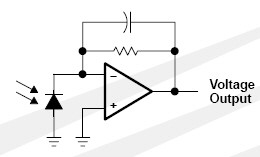
A light-to-voltage converter is wired in parallel with a resistor and is connected to a circuit with an LED and battery.
Figure 8. Light-to-voltage converter functional block diagram (TAOS, Inc., 2006).
Light (indicated by arrows) illuminates the photodiode sensor and generates a current. The operational amplifier (or "op amp," symbolized by the large triangle in the diagram) produces an output voltage that is proportional to the intensity of the light illuminating the photodiode. - A drawing of the actual component is shown in Figure 9. The round window contains the light-sensitve region. The component has three pins, as shown.
- Pin 1 should be connected to ground (black wire from the battery holder).
- Pin 2 should be connected to the positive supply voltage (red wire from the battery holder). The supply voltage should be between 2.5 and 5.5 V DC, so you can use either 2 or 3 AA batteries.
- Pin 3 is the output voltage, a signal that is proportional to the amount of light falling on the sensor. Pin 3 should be connected to one lead of the 10 kΩ resistor; the other lead of the resistor should be connected to ground.
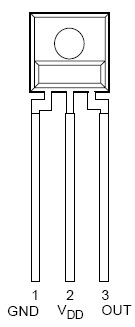
Figure 9. Drawing of light-to-voltage converter package (TAOS, Inc., 2006).
- Figure 10 is a schematic diagram of the complete circuit. In addition to the light-to-voltage converter, there is only one more component: a 10 kΩ resistor (RL). Connect the resistor from pin 3 to ground, as shown.
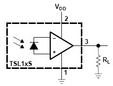
Diagram of a light-to-voltage converter wired to a battery that has an LED connected to it. A resistor is connected to the third pin.
Figure 10. Light-to-voltage converter circuit schematic (TAOS, Inc., 2006). - The output signal is the voltage drop across the 10 kΩ resistor. To read the output, use one alligator clip lead to connect the positive lead of the resistor to the red probe of your DMM, and another clip lead to connect the grounded lead of the resistor to the black probe of your DMM. Set your DMM to read DC Volts.
- Test the circuit with your digital multimeter (DMM). If you need help using a multimeter, check out the Science Buddies resource How to Use a Multimeter. Use clip leads to connect the DMM across the 10 kΩ resistor, and set the multimeter to read DC volts (the maximum signal will be about 5 V). When you shine a flashlight directly on the sensor, your multimeter should read between 1 and 5 V (depending on the brightness of the flashlight, and how close it is to the sensor). When you cover the sensor, the multimeter should read close to 0 V.
/-/https/www.sciencebuddies.org/cdn/Files/2905/5/ApMech_img014.jpg)
/-/https/www.sciencebuddies.org/cdn/Files/2906/5/ApMech_img015.jpg)
/-/https/www.sciencebuddies.org/cdn/Files/2907/5/ApMech_img016.jpg)
/-/https/i.ytimg.com/vi/ts0EVc9vXcs/maxresdefault.jpg)
Building the LED Circuit
- The + terminal of the 9 volt battery (red wire from battery snap) should be connected to the + lead of the LED (anode, longer lead).
- The − terminal of the battery should be connected to the 330 Ω resistor. Place the resistor near the battery so that it does not interfere with mounting the LED in front of the antenna.
- Connect the other end of the resistor to the − lead of the LED (cathode, shorter).
- To turn on the LED, connect the battery snap to the battery. Disconnect the battery when not in use.
Experimental Setup and Measurement
- Build the two antennas (one for the LED and one for the detector) using the template and instructions on the webpage Deep Dish Cylindrical Parabolic Template (Erskine, 2002). Tips:
- Use the styrofoam block as a guide to shape the antenna, but do not permanently attach it in front of the finished antenna. If your material does not hold its shape on its own, then glue the styrofoam supports to the top and bottom, not the center, of the antenna.
- Cover the antenna surface with aluminum foil before shaping.
- How far from the detector can you still pick up a signal without the reflector? Set the reflectors up facing each other farther than this distance.
- Using the wood dowels and blocks, rig up a support in front of each reflector to carry the LED or the detector. Mark off the dowels in one cm increments so that you can easily measure the position of the LED and the detector with respect to the reflectors.
- Use rubber bands to attach the LED and the light detector to each dowel.
- Make your LED light measurements in a darkened room. Use a shaded flashlight to check the reading on your DMM. Make sure that light from the flashlight does not fall on the light-to-voltage converter.
- Find the points in front of each reflector where you get the maximum response from the light detector.
- Move the LED in 1 or 2-cm increments, checking the reading on the light detector at each position.
- Move the light detector by 1 or 2 cm, and repeat.
- What happens if you block off a portion of the reflector in front of the LED?
- What happens if you block off a portion of the reflector in front of the detector?
Ask an Expert
Global Goals
The United Nations Sustainable Development Goals (UNSDGs) are a blueprint to achieve a better and more sustainable future for all.
/-/https/www.sciencebuddies.org/cdn/Files/19752/5/E-WEB-Goal-09.png)
Variations
- You can use parabolic reflectors to enhance the performance and security of your home wireless network. See the Science Buddies project The Point of a Parabola: Focusing Signals for a Better Wireless Network.
- Design an experiment to see how much further you can detect a light signal from an LED using a pair of parabolic reflectors.
- LEDs have different viewing angles, some narrow, some broad. Can you design a method for testing the intensity of light from an LED at different viewing angles? (The response from the light-to-voltage converter depends on its viewing angle. See the graph "Normalized Output Voltage vs. Angular Displacement," on page 4 of the light-to-voltage converter data sheet (Taos, Inc., 2006)). Online electronics suppliers such as Mouser Electronics, and Jameco Electronics have many different LEDs to choose from. Test your parabolic reflectors with several different types of LEDs, with a variety of viewing angles. If you block part of the parabolic reflector, can you measure a difference in the amount of light reaching the detector? Do you measure the same decrease for LEDs with wide viewing angles as for LEDs with narraow viewing angles?
- More advanced students might want to try designing an experiment to answer one or more of the following questions:
- Using similar construction methods as for the project described above, can you build an approximation of a 3-D parabolic antenna?
- How much further can you send a light signal with a 3-D parabola?
- Parabolas can be narrow and deep, or wide and flat. Which shape works best for sending a signal with an LED? Do some research on the "f/D" ratio for a parabolic antenna for this one.
Careers
If you like this project, you might enjoy exploring these related careers:
/-/https/careerdiscovery.sciencebuddies.org/cdn/Files/1223/17/iStock-971549326.jpg)
/-/https/careerdiscovery.sciencebuddies.org/cdn/Files/1242/20/iStock-113511101.jpg)
/-/https/careerdiscovery.sciencebuddies.org/cdn/Files/1233/17/unsplash-b28ac533a45f.jpg)
/-/https/careerdiscovery.sciencebuddies.org/cdn/Files/1442/17/unsplash-TXxiFuQLBKQ.jpg)

/-/https/img.youtube.com/vi/nhOyKdeRPXA/0.jpg)
/-/https/img.youtube.com/vi/XrJ_zLWFGFw/0.jpg)
/-/https/img.youtube.com/vi/67hDDnlqaKc/0.jpg)