Avoid the Shock of Shocks! Build Your Own Super-sensitive Electric Field Detector
Abstract
Wouldn't it be nice to avoid those nasty electric shocks you get after you have walked around on carpet and then touch a doorknob? These shocks are caused by static electricity. In this project, you will build a super-sensitive charge detector to investigate the electric fields created by static electricity. The detector can sense invisible electric fields before you touch something and get zapped, so try this project to avoid the shock of shocks!Summary
David Whyte, PhD, and Ben Finio, PhD, Science Buddies
Recommended Project Supplies
Objective
Build a sensitive electric field detector and use it to measure how well different materials hold electric charge.
Introduction
Static electricity is the accumulation of electrical charges on a surface, produced by the contact and separation of dissimilar materials. If you have ever received a shock when touching a doorknob, you have some firsthand experience with static electricity. The sparks created by static electricity can cause real problems, such as when they "fry" an electronic component in a computer.
Objects are usually electrically neutral, meaning they have an equal number of positive and negative charges. When two different materials are rubbed against each other, one of the materials often donates electrons to the other one. Electrons are elementary particles that carry a negative charge. If an item gives up electrons to another item, the first item will end up with a net positive charge. On the other hand, the item that now has extra electrons will have a net negative charge. Items that have a net negative or positive charge are surrounded by an invisible electric field, which attracts opposite charges and repels similar charges.
The materials listed below are ranked in order of their ability to hold or give up electrons. This ranking is called the triboelectric series. If two materials are rubbed together, the one higher on the list will donate electrons and become positively charged.
Triboelectric Series
- Positive (+)
- Human hands
- Glass
- Human hair
- Nylon
- Wool
- Fur
- Lead
- Silk
- Paper
- Cotton
- Steel
- Neutral (0)
- Wood
- Hard rubber
- Nickel, copper
- Brass, silver
- Gold, platinum
- Polyester
- Plastic wrap
- Polyurethane
- Polyethylene (like clear tape)
- Polypropylene
- Silicon
- Teflon
- Negative (-)
For this project, you will build a simple, but extremely sensitive, charge detector. When it is assembled, it will be able to sense the changes in the static electricity on your body as you walk over carpet, when you pet your cat or dog, or when you touch a plastic pen or brush to your hair. Figure 1 shows a circuit diagram for the charge detector. Circuit diagrams are schematics that electrical engineers use to represent circuits. Each symbol represents a different electronic component. However, do not worry if you do not understand the circuit diagram. The procedure of this project will provide step-by-step instructions for how to build the circuit on a breadboard.
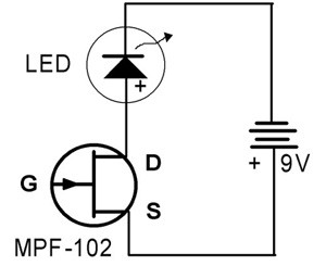 Image Credit: David Whyte, Science Buddies / Science Buddies
Figure 1. This is a circuit diagram for a solid-state charge detector. It can detect very weak electric fields.
As shown in Figure 1, the circuit has three components: a 9 V battery, a light-emitting diode (LED), and a field-effect transistor (FET). The field-effect transistor has three leads: a source (S), a gate (G), and a drain (D). A thorough description of how the field-effect transistor works would require delving into advanced electrical engineering, but the essential features can be seen in Figure 2. In semiconductors, electrons and "holes" act as charge carriers. The more-abundant charge carriers are called majority carriers. In N-type semiconductors they are electrons, whereas in P-type semiconductors they are holes. The field-effect transistor has a channel of N-type semiconducting material that allows electrons to carry a current. When the battery is connected to the transistor, a voltage is applied across this N-type semiconducting material.
Field-effect transistors are normally on devices, meaning that with no negative electric field, they allow maximum current to flow. In the middle of the N-channel is a region of P-type semiconductor. Around the P-type material, there is a depletion zone. There are fewer electrons in the depletion zone, so the bigger the depletion zone is, the higher the resistance. In the presence of a negative electric field, the depletion zone gets bigger, the current is decreased, and so the LED on the circuit is turned off.
The field-effect transistor circuit can be compared to a water faucet. In this analogy, the voltage is like the water pressure, and the field-effect transistor is like a faucet. When you open a faucet, water flows because of water pressure. The water will keep flowing until the faucet is closed. In the circuit, electrons flow through the FET and LED. The electrons flow because of the voltage supplied by the battery. Because electrons are flowing through the LED, it glows red. When the FET is "closed"—by bringing an object with a negative charge near the gate pin—electrons cannot flow through the circuit, and the LED light dims.
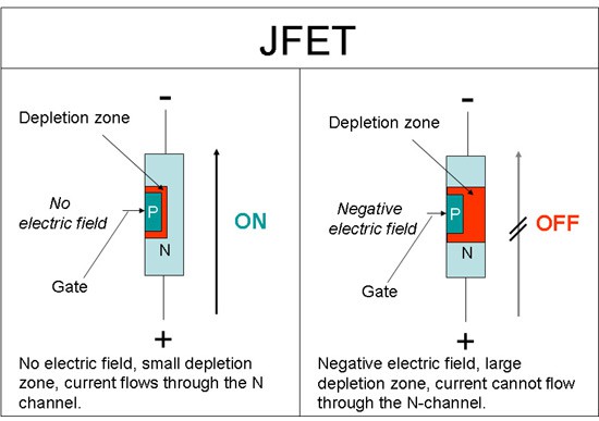 Image Credit: David Whyte, Science Buddies / Science Buddies
Figure 2. Schematic of an N-channel junction field-effect transistor (JFET, a sub-type of FET). It is made from a single piece of N-type semiconductor, constricted in the middle by P-type material forming the gate. Varying the gate voltage modulates the current flow through the device. When the gate voltage is made more negative, it constricts the current path in the region of the gate, increasing its resistance and reducing the current flow.
Terms and Concepts
Before you begin this science fair project, you should be familiar with these concepts:
- Static electricity
- Charge
- Electron
- Electric field
- Triboelectric series
- Circuit diagram
- Light-emitting diode (LED)
- Field-effect transistor (FET)
- Majority carrier
- N-type semiconductor
- P-type semiconductor
- Depletion zone
Questions
- What common household materials are available that are far apart on the triboelectric series?
- What combination of materials would you expect to create the greatest separation of charge when rubbed together?
- How does distance affect the strength of the electric field?
- In your own words, explain how the field-effect transistor compares to a water faucet.
Bibliography
This website is the source for the circuit used in this project. The website also has some entertaining variations of the basic project.
- Beaty, W.J. (2008, May). Ridiculously sensitive charge detector. Retrieved May 27, 2016.
Check out these websites for additional information.
- Henderson, T. (n.d.). Charging by Friction. The Physics Classroom. Retrieved May 27, 2016.
- Zavisa, J. (2000, April 1). How Van de Graaff Generators Work. Retrieved May 27, 2016.
- Nave, R. (2008, June). Junction Field Effect Transistor. Retrieved May 27, 2016.
- Kuphaldt, T. (n.d.). Static Electricity Sensor. All About Circuits. Retrieved May 27, 2016.
- Science Buddies Staff. (n.d.). Electricity, Magnetism, & Electromagnetism Tutorial.. Retrieved May 27, 2016.
- Science Buddies Staff. (n.d.). How to Use a Breadboard. Retrieved May 27, 2016.
Materials and Equipment 
Recommended Project Supplies
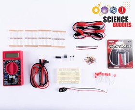
- Electronic Sensors Kit, available from our partner
Home Science Tools.
You will need these items from the kit. (See Table 1 in the Procedure if you do not know what these parts look like.)
- Breadboard
- 9 V battery
- 9 V battery snap connector
- Transistor
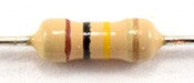
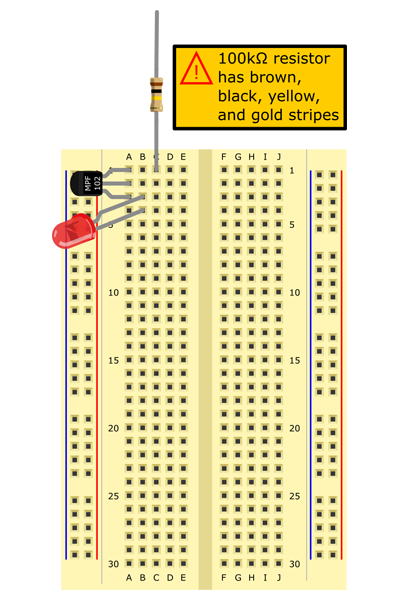
- 100 kΩ resistor
- Red LED
- You will also need to gather these items, not included in the kit:
- Several objects from the triboelectric series listed in the Background. This project works best with objects on opposite ends of the series (for example, human hair and a plastic item). It will be difficult to generate detectable charge with materials that are very close to each other in the series (for example, wood and cotton).
- Ruler
- Stopwatch
- Tape
- Lab notebook
Disclaimer: Science Buddies participates in affiliate programs with Home Science Tools, Amazon.com, Carolina Biological, and Jameco Electronics. Proceeds from the affiliate programs help support Science Buddies, a 501(c)(3) public charity, and keep our resources free for everyone. Our top priority is student learning. If you have any comments (positive or negative) related to purchases you've made for science projects from recommendations on our site, please let us know. Write to us at scibuddy@sciencebuddies.org.
Experimental Procedure
- Be very careful when assembling this circuit. It is possible to burn out the LED or the transistor by incorrectly connecting them to the 9 V battery. Make sure you carefully count the rows of the breadboard when you assemble your circuit.
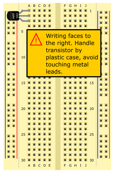
- Try to avoid touching the transistor's leads directly, especially the gate lead. Handle the transistor by the plastic packaging when you pick it up. A large static discharge can damage the transistor
Assembling Your Charge Detector Circuit
Important: your Sensor Kit contains two parts that look very similar: a transistor and a Hall effect sensor. They are both small black plastic parts with three metal legs. This project requires the transistor. When viewed from the top, it is bigger than the Hall effect sensor and rounded on one side, as shown in Figure 3. Make sure you use the transistor, or your circuit will not work!
 Image Credit: Ben Finio, Science Buddies / Science Buddies
Figure 3. Hall effect sensor (left) and transistor (right) viewed from the top.
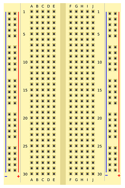
Assemble your charge detector circuit on a breadboard, as shown in the slideshow and described in Table 1. If this is your first time using a breadboard, refer to the Science Buddies resource How to Use a Breadboard for Electronics and Circuits. For a circuit schematic, see the Help section.
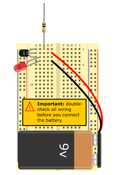

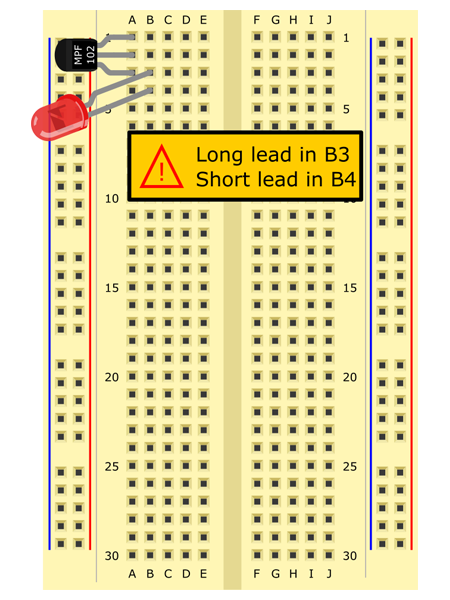
 Image Credit: Ben Finio, Science Buddies / Science Buddies
Slideshow with step-by-step instructions viewable online.
| Part | Picture | Breadboard Symbol | Location |
|---|---|---|---|
| Transistor |
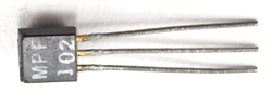 Image Credit: Ben Finio, Science Buddies / Science Buddies Image Credit: Ben Finio, Science Buddies / Science Buddies
|
A1, A2, A3. Writing must face to the right. | |
| LED |
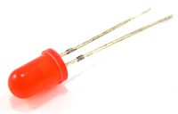 Image Credit: Ben Finio, Science Buddies / Science Buddies Image Credit: Ben Finio, Science Buddies / Science Buddies
|
Long lead in B3 Short lead in B4 |
|
| 100 kΩ resistor | One lead in C1 | ||
| 9 V battery and snap connector | Red lead to E2 Black lead to E4 |


Measuring Electric Fields
- Learn how to use your charge detector. Once you have finished assembling it, the LED should be on (see Figure 4). Try rubbing different objects from the triboelectric series against each other and bringing them near the "antenna" (the free lead of the 100 kΩ resistor). What happens? Here are some tips for using the circuit:
- When you rub two objects together, the one lower on the triboelectric series (meaning it has a negative charge) should cause the LED to go out when you bring it near the circuit. The object higher on the series (with a positive charge) may cause the LED to get slightly brighter, but this can be difficult to see since the LED is already on. This project works best if you bring negatively charged objects near the circuit.
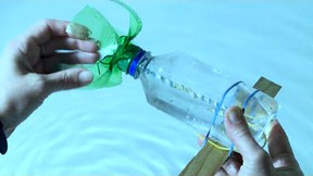
- The charge on an object will dissipate if you handle it, especially if your hands are slightly damp. By handling the object, the charged particles are transferred from the object to your skin. You can keep the charge from being lost by isolating the charged object; for example, by quickly placing it on an insulating surface (like a wooden tabletop) next to the circuit, or by suspending the object with string made out of nylon, or some other insulating material.
- The LED might turn off completely after the circuit is exposed to a strong positive field. You can "reset" the circuit by tapping the resistor leads with your finger, or by waving a negatively charged object (such as a plastic pen that has been run through your hair) near the antenna.
- See the FAQ if you have trouble with your circuit.
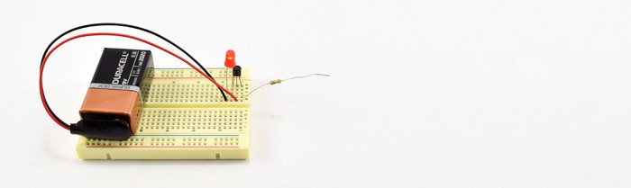 Image Credit: Ben Finio, Science Buddies / Science Buddies
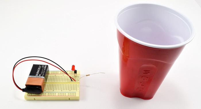
Figure 4. Top: the LED is on when no objects are near the antenna. Bottom: the LED turns off when a negatively-charged object (in this case, a plastic cup that was just rubbed against human hair) is brought near the antenna.
- Select one material from the positive end of the triboelectric series (human hair works well) and an assortment of materials in the neutral and negative parts of the series. You will rub all the other materials against the first one.
- If possible, prepare all your materials in one place, on a single work surface, so you can do the experiment without walking around. Moving around (especially on carpet) can cause static electricity to build up on your body, and this can affect your results.
- Rub two materials together and immediately place the negatively charged one directly next to the antenna. Use a stopwatch to time how long it takes the LED to come back on. Repeat this for each of your materials (make sure you rub each material the same number of times), and do at least three trials for each material.
- Set up a ruler to measure the distance from the antenna. Rub two materials together and then slowly move the negatively charged one toward the antenna until the LED goes out. Record the distance at which the LED goes out. Again, repeat this for each of your other materials and do at least three trials. Remember that the objects might lose charge as you hold them, so you might need to devise a technique to move the objects closer to the antenna without touching them. For example, you could slide them on a wooden block or suspend them from a string.
- Analyze your data. Which material holds its charge the longest? Which one generates the strongest electric field? If you rank the materials for each category, is the order the same? Are your results consistent with what you would expect based on the triboelectric series?
- There are many other things you can do with this circuit. See the Variations section of this project and the Experiments section of this page for more ideas.
Troubleshooting
For troubleshooting tips, please read our FAQ: Avoid the Shock of Shocks! Build Your Own Super-sensitive Electric Field Detector.
Ask an Expert
Variations
- Try using different lengths of wire as an antenna for your circuit. Your kit comes with several short jumper wires and much longer alligator clips, which you could also use. Does a longer antenna increase the circuit's sensitivity?
- Keep track of the humidity and record how it affects your static electricity experiments.
- Build a permanent version of the circuit using solder to make the connections.
- Charge an object, for example, by running a pen through your hair. Now support the pen with different materials and place it near the antenna to see which is best at keeping the object charged.
- Can you detect electric fields that are created when you pet your cat or dog?
- Charge an object, hold it near the antenna to dim the LED light, and then pass other objects between the object and the antenna. What happens?
- Does changing the number of times you rub an object back and forth to charge it affect either how long it will stay charged or the distance at which you can detect its electric field? Why or why not?
Frequently Asked Questions (FAQ)
Careers
If you like this project, you might enjoy exploring these related careers:


Contact Us
If you have purchased a kit for this project from Science Buddies, we are pleased to answer any question not addressed by the FAQ above.In your email, please follow these instructions:
- What is your Science Buddies kit order number?
- Please describe how you need help as thoroughly as possible:
Examples
Good Question I'm trying to do Experimental Procedure step #5, "Scrape the insulation from the wire. . ." How do I know when I've scraped enough?
Good Question I'm at Experimental Procedure step #7, "Move the magnet back and forth . . ." and the LED is not lighting up.
Bad Question I don't understand the instructions. Help!
Good Question I am purchasing my materials. Can I substitute a 1N34 diode for the 1N25 diode called for in the material list?
Bad Question Can I use a different part?
Contact Us
Related Links
- Science Fair Project Guide
- Other Ideas Like This
- Electricity & Electronics Project Ideas
- My Favorites
- How Well Do Different Materials Create Static Electricity?


