How to Use a Multimeter
Multimeter Overview
Multimeter Overview
/-/https/i.ytimg.com/vi/ts0EVc9vXcs/maxresdefault.jpg)
Not sure what a multimeter is or what you can do with one? Then you're in the right place! Below is an overview of what multimeters are and what they are useful for. To learn how to use a multimeter, to find multimeter usage ideas, or to find labeled photographs of assorted multimeter models, click on the quick links in this multimeter tutorial.
/-/https/www.sciencebuddies.org/cdn/Files/13177/6/how-to-use-a-multimeter-thumbnail.jpg)
This section includes answers to the following questions:
- What is a multimeter?
- What can multimeters measure?
- What are voltage, current, and resistance?
- What are direct current (DC) and alternating current (AC)?
- What are series and parallel circuits?
- What do all the symbols on the front of the multimeter mean?
- What are the red and black wires (probes)? Where do I plug them in?
What is a multimeter?
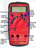
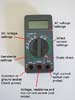
A multimeter is a handy tool that you use to measure electricity, just like you would use a ruler to measure distance, a stopwatch to measure time, or a scale to measure weight. The neat thing about a multimeter is that unlike a ruler, watch, or scale, it can measure different things — kind of like a multi-tool. Most multimeters have a knob on the front that lets you select what you want to measure. Below is a picture of a typical multimeter. There are many different multimeter models; visit the multimeter gallery for labeled pictures of additional models.
/-/https/www.sciencebuddies.org/cdn/Files/4802/11/multimeter-DT830L.jpg)
Figure 1. A typical multimeter.
What can multimeters measure?
Almost all multimeters can measure voltage, current, and resistance. See the next section for an explanation of what these terms mean, and click on the Using a Multimeter section for instructions on how to make these measurements.
Some multimeters have a continuity check, resulting in a loud beep if two things are electrically connected. This is helpful if, for instance, you are building a circuit and connecting wires or soldering; the beep indicates everything is connected and nothing has come loose. You can also use it to make sure two things are not connected, to help prevent short circuits.
Some multimeters also have a diode check function. A diode is like a one-way valve that only lets electricity flow in one direction. The exact function of the diode check can vary from multimeter to multimeter. If you're working with a diode and can't tell which way it goes in the circuit, or if you're not sure the diode is working properly, the check feature can be quite handy. If your multimeter has a diode check function, read the manual to find out exactly how it works.
Advanced multimeters might have other functions, such as the ability to measure and identify other electrical components, like transistors or capacitors. Since not all multimeters have these features, we will not cover them in this tutorial. You can read your multimeter's manual if you need to use these features.
What are voltage, current, and resistance?
If you haven't heard of these terms before, we'll give a very simple introductory explanation here. You can read more about voltage, current, and resistance in the References section. Remember that voltage, current, and resistance are measurable quantities that are each measured in a unit that has a symbol, just like distance is a quantity that can be measured in meters, and the symbol for meters is m.
- Voltage is how hard electricity is being "pushed" through a circuit. A higher voltage means the electricity is being pushed harder. Voltage is measured in volts. The symbol for volts is V.
- Current is how much electricity is flowing through the circuit. A higher current means more electricity is flowing. Current is measured in amperes. The symbol for amperes is A.
- Resistance is how difficult it is for electricity to flow through something. A higher resistance means it is more difficult for electricity to flow. Resistance is measured in ohms. The symbol for ohms is Ω (the capital Greek letter omega).
Technical Note
The symbol that is used for a unit is usually different than the symbol for a variable in an equation. For example, voltage, current, and resistance are related by Ohm's law (see the References section to learn more about Ohm's law):
which is usually expressed as
In this equation, V represents voltage, I represents current, and R represents resistance. When referring to the units volts, amps, and ohms, we use the symbols V, A, and Ω, as explained above. So, "V" is used for both voltage and volts, but current and resistance have different symbols for their variables and units. Don't worry if this seems confusing; this table will help you keep track:
| Variable | Symbol | Unit | Symbol |
|---|---|---|---|
| Voltage | V | Volts | V |
| Current | I | Ampere | A |
| Resistance | R | Ohm | Ω |
This is very common in physics. For example, in many equations, "position" and "distance" are represented by the variables "x" or "d," but they are measured in the unit meters, and the symbol for meters is m.
A simple analogy to better understand voltage, current, and resistance: imagine water flowing through a pipe. The amount of water flowing through the pipe is like current. More water flow means more current. The amount of pressure making the water flow is like voltage; a higher pressure will "push" the water harder, increasing the flow. Resistance is like an obstruction in the pipe. For instance, a pipe that is clogged with debris or objects will be harder for water to flow through, and will have a higher resistance than a pipe that is free of obstruction.
What are direct current (DC) and alternating current (AC)?
Direct current (abbreviated DC) is current that always flows in one direction. Direct current is supplied by everyday batteries—like AA and AAA batteries—or the one in your cell phone. Most of the Science Buddies projects you do will probably involve measuring direct current. Different multimeters have different symbols for measuring direct current (and the corresponding voltage), usually "DCA" and "DCV," or "A" and "V" with a straight bar above or next to them. See "What do all the symbols on the front of the multimeter mean?" for more information about the abbreviations and symbols on multimeters.
Alternating current (abbreviated AC) is current that changes direction, usually many times in one second. The wall outlets in your house provide alternating current that switches directions 60 times per second (in the U.S., but 50 times per second in other countries). (Warning: Do not use a multimeter to measure the wall outlets in your home. This is very dangerous.) If you need to measure alternating current in a circuit, different multimeters have different symbols to measure it (and the corresponding voltage), usually "ACA" and "ACV," or "A" and "V" with a squiggly line (~) next to or above them.
What are series and parallel circuits?
When you take measurements with a multimeter, you will need to decide whether to attach it to your circuit in series or in parallel, depending on what you want to measure. In a series circuit, each circuit element has the same current. So, to measure current in a circuit, you must attach the multimeter in series. In a parallel circuit, each circuit measurement has the same voltage. So, to measure voltage in a circuit, you must attach your multimeter in parallel. To learn how to take these measurements, see the Using a Multimeter section.
Figure 2 shows basic series and parallel circuits, without a multimeter connected. To learn more about voltage, current, and resistance in series and parallel circuits, check out the References section.
/-/https/www.sciencebuddies.org/cdn/Files/4803/20/series-circuit-parallel-circuit.png)
Figure 2. In a basic series circuit (left), each element has the same current (but not necessarily the same voltage; that will only happen if their resistances are all the same). In a basic parallel circuit (right), each element has the same voltage (but not necessarily the same current; that will only happen if their resistances are all the same).
What do all the symbols on the front of the multimeter mean?
You might be confused by all the symbols on the front of your multimeter, especially if you don't actually see words like "voltage," "current," and "resistance" spelled out anywhere. Don't worry! Remember from the "What are voltage, current, and resistance?" section that voltage, current, and resistance have units of volts, amps, and ohms, which are represented by V, A, and Ω respectively. Most multimeters use these abbreviations instead of spelling out words. Your multimeter might have some other symbols, which we will discuss below.
Most multimeters also use metric prefixes. Metric prefixes work the same way with units of electricity as they do with other units you might be more familiar with, like distance and mass. For example, you probably know that a meter is a unit of distance, a kilometer is one thousand meters, and a millimeter is one thousandth of a meter. The same applies to milligrams, grams, and kilograms for mass. Here are the common metric prefixes you will find on most multimeters (for a complete list, see the References section):
- µ (micro): one millionth
- m (milli): one thousandth
- k (kilo): one thousand
- M: (mega): one million
These metric prefixes are used in the same way for volts, amps, and ohms. For example, 200kΩ is pronounced "two hundred kilo-ohms," and means two hundred thousand (200,000) ohms.
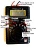
Some multimeters are "auto-ranging," whereas others require you to manually select the range for your measurement. If you need to manually select the range, you should always pick a value that is slightly higher than the value you expect to measure. Think about it like using a ruler and a yardstick. If you need to measure something that is 18 inches long, a 12-inch ruler will be too short; you need to use the yardstick. The same applies to using a multimeter. Say you are going to measure the voltage of a AA battery, which you expect to be 1.5V. The multimeter on the left in Figure 3 has options for 200mV, 2V, 20V, 200V, and 600V (for direct current). 200mV is too small, so you would pick the next highest value that works: 2V. All of the other options are unnecessarily large, and would result in a loss in accuracy (it would be like using a 50-foot tape measure that only has markings every foot, and no inch markings; it isn't as accurate as using a yardstick with 1-inch markings).
/-/https/www.sciencebuddies.org/cdn/Files/4804/7/fig3_sparkfun-digital-multimeter.jpg)
Figure 3. The multimeter on the left is manual-ranging, with many different options (indicated by metric prefixes) for measuring different amounts of voltage, current, and resistance. The multimeter on the right is auto-ranging (note how it has fewer options for the selection knob), meaning it will automatically select the appropriate range.
What do the other symbols on the multimeter mean?
You might have noticed some other symbols besides V, A, Ω, and metric prefixes on the front of your multimeter. We'll explain some of those symbols here, but remember, all multimeters are different, so we cannot cover every possible option in this tutorial. Check your multimeter's manual if you still can't figure out what one of the symbols means. You can also browse our multimeter gallery to see labeled pictures of different multimeters.
| Multimeter Symbol | Samples |
|---|---|
| ~ (squiggly line): You might see a squiggly line next to or above a V or A on the front of your multimeter, in addition to metric prefixes. This stands for alternating current (AC). Note that the voltage in an AC circuit is usually referred to as "AC voltage" (even though it sounds strange to say "alternating current voltage"). You use these settings when you are measuring a circuit with alternating current (or voltage). | /-/https/www.sciencebuddies.org/cdn/Files/4812/6/multimeter-AC-voltage-symbols.jpg) |
| —, - - - (solid line or dashed line): Like the squiggly line, you might see this next to or above a V or an A. The straight lines stand for direct current. You use these settings when you are measuring a circuit with direct current (e.g., most circuits that are powered by a battery). | /-/https/www.sciencebuddies.org/cdn/Files/4813/6/multimeter-DC-voltage-symbols.jpg) |
| DCV, ACV, ACA, DCA, VAC, or VDC: Sometimes, instead of (or in addition to) using squiggly or dashed lines, multimeters will use the abbreviations AC and DC, which stand for alternating current and direct current, respectively. Note that some multimeters might have AC and DC after the V and A, instead of before. | /-/https/www.sciencebuddies.org/cdn/Files/4814/7/multiimeter-AC-DC-voltage-symbols.jpg) |
| Continuity check (series of parallel arcs): This is a setting used to check if two things are electrically connected. The multimeter will beep if there is a conductive path between the two probe tips (meaning, if the resistance is very close to zero), and will not make any noise if there is no conductive path. Note that sometimes the continuity check can be combined with other functions on a single setting. | /-/https/www.sciencebuddies.org/cdn/Files/4815/6/continuity-check-symbols.jpg) |
| Diode check (triangle with some lines through it): This function is used to test a diode, which is like a one-way valve for electricity; it only lets current flow in one direction. The exact function of the diode check can be different on different multimeters. Check your multimeter's manual to learn about how the diode check function works for your model. | /-/https/www.sciencebuddies.org/cdn/Files/4816/6/diode-check-symbols.jpg) |
What are the red and black wires (probes)? Where do I plug them in?
Your multimeter probably came with red and black wires that look something like the ones in Figure 4. These wires are called probes or leads (pronounced "leeds"). One end of the lead is called a banana jack; this end plugs into your multimeter (Note: some multimeters have pin jacks, which are smaller than banana jacks; if you need to buy replacement probes, be sure to check your multimeter's manual to find out which kind you need). The other end is called the probe tip; this is the end you use to test your circuit. Following standard electronics convention, the red probe is used for positive, and the black probe is used for negative.
/-/https/www.sciencebuddies.org/cdn/Files/4805/6/fig4_multimeter-probes-labeled.jpg)
Figure 4. A typical pair of multimeter probes.
Although they come with two probes, many multimeters have more than two places in which to plug the probes, which can cause some confusion. Exactly where you plug the probes in will depend on what you want to measure (voltage, current, resistance, continuity test, or diode test) and the type of multimeter you have. We have provided one example in the images below—and you can check our gallery for a multimeter similar to yours—but since all multimeters are slightly different, you might need to consult the manual for your multimeter.
Most multimeters (except for very inexpensive ones) have fuses to protect them from too much current. Fuses "burn out" if too much current flows through them; this stops electricity from flowing, and prevents damage to the rest of the multimeter. Some multimeters have different fuses, depending on whether you will be measuring high or low current, which determines where you plug the probes in. For example, the multimeter shown in Figure 5 has one fuse for 10 amps (10A) and one fuse for 200 milliamps (200mA).
/-/https/www.sciencebuddies.org/cdn/Files/4806/6/fig5_sparkfun-digital-multimeters.jpg)
The left image is a multimeter with no probes inserted. The center image is a multimeter that has a black probe inserted into the center port and a red probe inserted into the right-most port. This setup is rated to measure current under 200 milliamps. The right image shows a multimeter that has a black probe inserted into the center port and a red probe inserted into the left-most port. This setup is rated to measure current up to 10 amps.
Figure 5. This multimeter has three different ports labeled 10A, COM (which stands for "common"), and mAVΩ. The fuse between mAVΩ and COM is rated for 200mA, which is a relatively "low" current. So, in order to measure small currents-or voltage or resistance (very little current flows through the multimeter when measuring voltage or resistance)—you plug the black probe into COM and the red probe into the port labeled mAVΩ. The fuse between 10A and COM is rated for 10A, so to measure high currents, you plug the black probe into COM and the red probe into the port labeled 10A.
Using a Multimeter
Using a Multimeter
Do you have a multimeter but are confused about how to use it or are getting unexpected readings? If so, the sections below will help you sort through what to do. If there are words or concepts you do not understand, or symbols on your multimeter that puzzle you, return to the Multimeter Overview tab. If you are looking for multimeter usage ideas or labeled photographs of assorted multimeter models, then visit the other sections in this multimeter tutorial.
This section includes answers to the following questions:
- How do I measure voltage?
- How do I measure current?
- How do I measure resistance?
- How do I do a continuity check?
- How do I do a diode check?
- How do I know which scale to pick for voltage, current, or resistance, and how do I read the numbers at different scales?
- My multimeter isn't working! What's wrong?
- How do I know if I need to change the fuse?
- How do I change the fuse?
How do I measure voltage?
To measure voltage, follow these steps:
- Plug your black and red probes into the appropriate sockets (also referred to as "ports") on your multimeter. For most multimeters, the black probe should be plugged into the socket labeled "COM," and the red probe into the socket labeled with a "V" (it might also have some other symbols). Remember to check out our image gallery, the Multimeter Overview section, or your multimeter's manual if you have trouble identifying the right socket.
- Choose the appropriate voltage setting on your multimeter's dial. Remember that most battery-powered circuits will have direct current, but the setting you select will depend on the science project you are doing. If you are working with a manual-ranging multimeter, you can estimate the range you need based on the battery (or batteries) powering your circuit. For example, if your circuit is powered by a single 9V battery, it probably doesn't make sense to select the setting for 200V, and 2V would be too low. If available, you would want to select 20V.
- Touch the probe tips to your circuit in parallel with the element you want to measure voltage across (refer to the Multimeter Overview section for an explanation of series and parallel circuits). For example, Figure 6 shows how to measure the voltage drop across a lightbulb powered by the battery. Be sure to use the red probe on the side connected to the positive battery terminal, and the black probe on the side connected to the negative battery terminal (nothing will be harmed if you get this backwards, but your voltage reading will be negative).
/-/https/www.sciencebuddies.org/cdn/Files/4807/14/multimeter-parallel-measure-voltage.png)
Figure 6. Measuring voltage across a lightbulb by attaching the multimeter probes in parallel. Current flow is represented by the yellow arrows. In voltage-measurement mode, the multimeter's resistance is very high, so almost all of the current flows through the lightbulb, and the multimeter does not have a big impact on the circuit. Notice how the knob has been set to measure DC voltage (DCV) and the red probe is plugged into the correct port for measuring voltage (labeled "VΩ" because it is also used to measure resistance).
- If your multimeter is not auto-ranging, you might need to adjust the range. If your multimeter's screen just reads "0," then the range you have selected is probably too high. If the screen reads "OVER," "OL," or "1" (these are different ways of saying "overload"), then the range you have selected is too low. If this happens, adjust your range up or down as necessary. Remember that you might need to consult your multimeter's manual for specifics about your model.
How do I measure current?
To measure current, follow these steps:
- Plug your red and black probes into the appropriate sockets (also referred to as "ports") on the multimeter. For most multimeters, the black probe should be plugged into the socket labeled "COM." There might be multiple sockets for measuring current, with labels like "10A" and "mA". Note:It is always safer to start out with the socket that can measure a larger current. Plug the red socket into the high-current port.
- Choose the appropriate current setting on your multimeter. Remember to check if your circuit is direct current or alternating current, and that almost all battery-powered circuits will be direct current. If your meter is not auto-ranging, you might need to guess at the scale to use (you can change this later if you don't get a good reading).
- Connect the multimeter probes in series to the current you want to measure (refer to the Multimeter Overview section for an explanation of series and parallel circuits). For example, Figure 7 shows how to measure the current through a lightbulb that is powered by a battery. Be sure to use the red probe toward the battery's positive side, otherwise your current reading will be negative.
/-/https/www.sciencebuddies.org/cdn/Files/4808/13/multimeter-series-measure-current.png)
To measure the current through a lightbulb the multimeter becomes part of the circuit and transfers electricity from the battery to the lightbulb. The positive probe of the multimeter (red) is connected to the positive side of a battery while the negative probe of the multimeter (black) is connected to one lead of a lightbulb. The free lightbulb lead is then connected to the negative side of the battery using wire. Current will flow from the battery to the multimeter and then into the lightbulb.
Figure 7. Measuring the current through a lightbulb by attaching a multimeter in series. Current flow is represented by the yellow arrows. In current-measurement mode, the multimeter's resistance is very low, so the current can easily flow through the multimeter without affecting the rest of the circuit. Notice how the knob has been set to measure direct current (DCA) and the red probe is plugged into the port for measuring current, labeled with an "A."
- If your multimeter is not auto-ranging, you might need to adjust the range. If your multimeter's screen just reads "0," then the range you have selected is probably too high. If the screen reads "OVER," "OL," or "1" (these are different ways of saying "overload"), then the range you have selected is too low. If this happens, adjust your range up or down as necessary. Remember that you might need to consult your multimeter's manual for specifics about your model.
How do I measure resistance?
To measure resistance, follow these steps:
- Plug your red and black probes into the appropriate sockets on your multimeter. For most multimeters, the black probe should be plugged into the socket labeled "COM," and the red probe should be plugged into the socket labeled with an "Ω" symbol.
- Choose the appropriate resistance measurement setting on your multimeter's dial. If you have an estimate for the resistance you will be measuring (for example, if you are measuring a resistor with a known value), that will help you pick the range.
- Important: Turn off the power supply to your circuit before measuring resistance. If your circuit has a power switch, you can do this by turning the switch "off." If there is no switch, you can remove the batteries. If you do not do this, your reading might be incorrect. If your circuit has multiple components, you might need to remove the component you want to measure in order to accurately determine its resistance. For example, if your circuit has two resistors in parallel, you will have to remove one resistor to measure their resistances individually.
Connect one of your multimeter's probes to each side of the object whose resistance you want to measure. Resistance is always positive and the same in both directions, so it does not matter if you switch the black and red probes in this case (unless you are dealing with a diode, which acts like a one-way valve for electricity, so it has a high resistance in one direction and a low resistance in the other direction). Figure 8 shows how to measure the resistance of a lightbulb.
/-/https/www.sciencebuddies.org/cdn/Files/4809/13/multimeter-measure-resistance.png)
Figure 8. Measuring the resistance of a lightbulb using a multimeter. Notice how the lightbulb has been disconnected from the circuit. The multimeter supplies its own small amount of current, which allows it to measure the resistance. Notice how the knob has been set to the "Ω" to measure resistance, and the red probe is plugged into the proper port to measure resistance (labeled "VΩ" since it is also used to measure voltage).
- If your multimeter is not auto-ranging, you might need to adjust the range. If your multimeter's screen just reads "0," then the range you have selected is probably too high. If the screen reads "OVER," "OL," or "1" (these are different ways of saying "overload"), then the range you have selected is too low. If this happens, adjust your range up or down as necessary. Remember that you might need to consult your multimeter's manual for specifics about your model.
How do I do a continuity check?
To do a continuity check (which ensures that there is a conductive path between two points in your circuit), follow these steps:
- Set your multimeter to the continuity check symbol. Remember that this symbol might not look the same on all multimeters (and some multimeters do not have it at all), so check out the Multimeter Overview section or our multimeter image gallery to see examples.
- Plug your probes into the appropriate sockets. On most multimeters, the black probe should go into the socket labeled "COM," and the red probe should go into the same socket you would use to measure voltage or resistance (not current), labeled with a V and/or an Ω.
- Important: Turn off the power supply to your circuit before doing a continuity check. If your circuit has a power switch, you can do this by turning the switch "off." If there is no switch, you can remove the batteries.
Touch two parts of your circuit with the probes. If the two parts of the circuit are electrically connected with very little resistance between them, your multimeter should beep. If they are not connected, it will not make a noise and might display something on the screen such as "OL," "OVER," or "1," which all stand for "overload." The easiest way to test this function with your multimeter is to check it with a single piece of conductive material (most metals) and a piece of non-conducting material, like wood or plastic. See Figure 9 for an example.
/-/https/www.sciencebuddies.org/cdn/Files/13175/7/multiemter-continuity-test-beep-1.png)
/-/https/www.sciencebuddies.org/cdn/Files/13176/8/multiemter-continuity-test-beep-2.png)
Figure 9. Using a multimeter to do a continuity test. If a conductive path is formed between the probe tips, the multimeter will beep. If the conductive path is broken (possibly due to a wire that has come loose in your circuit, or a bad solder connection), the multimeter will not beep. Notice how the knob has been set to the symbol for continuity and the red probe is plugged into the VΩ port (this port is not always labeled with the continuity symbol).
How do I do a diode check?
The diode check feature is useful to determine in which direction electricity flows through a diode. The exact operation of the "diode check" function will vary for different multimeters, and some multimeters do not have a diode check feature at all. Because of this variety, and because the feature is not required for most Science Buddies projects, we have not included directions here. If you need to do a diode check, consult the manual for your multimeter.
How do I know which scale to pick for voltage, current, or resistance, and how do I read the numbers at different scales?
If your multimeter is not auto-ranging, knowing which scale to pick can be tricky, especially if you are not very familiar with metric prefixes. Here are two rules of thumb you can follow for measuring voltage, current, and resistance:
- Voltage: Many manual-ranging multimeters have settings for 200mV, 2V, and 20V. It is very unlikely that battery-powered circuits will exceed 20V (for example, two 9V batteries connected in series will provide a maximum of 18V). A single AA or AAA battery supplies 1.5V. Two AA or AAA batteries combined in a battery pack will provide 3V, four will provide 6V, and eight will provide 12V. So, if you know what type of batteries (and how many), are powering your circuit, you can pick a starting range to measure voltage. Remember that you want to pick the next highest voltage setting (just like with measuring distance; you would need a yardstick— not a 12-inch ruler— to measure something that is 18 inches long). So, for a circuit powered by a single AA battery (1.5V), you would select the 2V setting. For a circuit powered by a 9V battery, you would select 20V.
- Current: When measuring current, it is always a good idea to start out with the highest possible current setting (and the appropriate high-current socket, if your multimeter has multiple sockets to measure current), in order to avoid blowing a fuse. If the current you measure is low enough to safely use your low-current settings and socket, then you can take a new reading to get a more-accurate measurement. For example, say your multimeter has a socket with a 10A fuse and one with a 200mA fuse. Using the 10A socket, you measure a current of 150mA. Then it would be safe to measure again with the 200mA socket (and a lower setting on the knob).
- Resistance: If you are measuring an object with a known resistance, you can use that value to choose the appropriate resistance setting. As with current and voltage, you need to pick the next largest resistance value on your scale. For example, to measure a 4.7kΩ resistor, you would select 20kΩ. If you are measuring an object with unknown resistance, you will just have to guess, but it is difficult to damage your multimeter or the object you are testing when measuring resistance, so this is not a big problem.
The same value might appear differently when measured with a different scale selected on the multimeter dial. For an example, let's use measuring the DC voltage from a AA battery—which we expect to be 1.5V—using a multimeter that has settings for 200mV, 2V, 20V, 200V, and 600V. When measuring the battery with each setting, we get these readings:
| Multimeter Dial Setting | Screen Reading |
|---|---|
| 200mV | 1 . |
| 2V | 1.607 |
| 20V | 1.60 |
| 200V | 1.6 |
| 600V | 001 |
The "1 ." is this multimeter's way of saying that it is "overloaded"—the value of 1.6V is outside the selected range of 200mV. Other multimeters might display "OVER" or "OL" when this happens. Notice that as the range increases, the accuracy decreases. At the 2V setting, the reading displays 3 decimal places. At the 200V setting, the reading only displays one decimal place.
You might also need to take metric prefixes into account when reading the number from the multimeter screen. For example, suppose your screen reads "6.1" when you are measuring current with the "10A" setting. This means your current measurement is 6.1 amps. However, if the screen reads "6.1" when you have the current dial set to 20mA, this means you are measuring 6.1 milliamps.
My multimeter isn't working! What's wrong?
Don't panic! There are several common mistakes that can be easily fixed.
- Make sure your multimeter has fresh batteries.
- Some multimeters have an auto power-saving feature, and will turn off after a certain period of inactivity. If this happens, turn your multimeter's dial to "off" and then turn it on again.
- Make sure you have your probes plugged into the correct ports for what you want to measure (see the "How do I measure..." sections above).
- Make sure you are connecting your probes to your circuit in the correct manner (series or parallel) for what you want to measure (see the "How do I measure..." sections above).
- Make sure you have the correct setting chosen on your multimeter dial for what you want to measure; for example, if you need to measure DC voltage, make sure you don't have current, resistance, or AC voltage selected on the dial.
- If your multimeter is not auto-ranging, you might need to manually adjust your range. If your multimeter screen always reads "0," this might mean the range you have selected is too high. If it reads "OL," "OVER," or "1," the range you have selected could be too low. Each multimeter is different, so you might need to read your multimeter's manual to find out what the display on the screen means. You can then adjust the range accordingly.
- For example, if you are trying to measure the voltage of a 9V battery, but have your multimeter set to 2 DCV, this range is too small and you would have to increase it to a higher value, such as 20 DCV.
Still not working? You might have blown out a fuse in your multimeter. See the next section for suggestions.
How do I know if I need to change the fuse?
Some multimeters have a fuse (or multiple fuses) that will "burn out" when too much current flows through them, which then prevents more electricity from flowing, and hopefully saves the rest of the multimeter from damage. In some multimeters, these fuses can be replaced if they burn out, but instructions for replacing them (and figuring out if they need to be replaced at all) will vary for different multimeter models.
You will probably need to open up your multimeter to access the fuses (Important: Always disconnect the probes before you do this). Some multimeters have covers that will pop or slide off, and some have screws that must be removed first. Fuses usually look like small, glass cylinders with metal caps on the end and a thin wire running down the middle:
/-/https/www.sciencebuddies.org/cdn/Files/4811/10/electrical-fuse_img.jpg)
Figure 10. A typical fuse.
If a fuse has burned out, it might be visibly blackened or charred. The wire on the inside might have completely burned away, and no longer be visible.
How do I change the fuse?
Important: Always disconnect the leads from your multimeter before opening the cover to change the fuse.
Instructions for changing the fuse vary with each multimeter model, so you will need to check your multimeter's manual for instructions. This tutorial from SparkFun provides directions for changing a fuse on their brand of multimeter, but remember that these directions might not apply to your model. Note that in some multimeters-especially in inexpensive ones-you might not be able to change the fuse.
Multimeter Fun
Multimeter Fun
In this multimeter tutorial, we have already covered what a multimeter is and how to use it. This section will provide some suggestions of practical and interesting things to do with a multimeter.
This section answers the questions:
- What can I do with a multimeter around the house?
- What shouldn't I do with my multimeter?
- Which Science Buddies projects require a multimeter?
What can I do with a multimeter around the house?
Remember that the primary purpose of a multimeter is to test circuits and electrical components in an experiment or science project that involves electronics. What if you don't have a circuit to test? Here are a couple suggestions for quick experiments you can do with a multimeter around your house.
- Test batteries! Have you ever wondered if a device or toy stopped working because the batteries were dead? With a multimeter, you can make sure batteries are actually dead before recycling them by testing their voltage. Remember that fresh AA and AAA batteries should supply about 1.5V (a fresh alkaline cell will measure about 1.6V with nothing else attached). However, batteries will effectively be "dead" long before they reach 0V. For example, if a battery is supplying 0.7V, that probably isn't enough to power most household devices that are expecting 1.5V from the battery.
- Do you have rechargeable batteries? You can test their voltage over time as they recharge, and then make a plot of voltage vs. charge. How long does it take for the voltage to stop increasing? Is the graph a straight line?
- Do you have anything you can take apart with a circuit board inside, like an old toy, or a TV remote? Use the continuity check on your multimeter (if it has one) to test which parts of the circuit are directly connected to each other. (Warning: Old circuit boards are constructed with a lead-based solder, which is toxic. Always wash your hands carefully after handling solder, and check your local waste disposal guidelines to see if there are special rules about disposing of lead as hazardous waste.)
- Set your multimeter to measure resistance, and have everyone in your house take turns grabbing the metal tips of the probes (one in each hand). Who has the highest resistance? The lowest?
- Use the continuity check or resistance measurement to test different materials in your house. Which ones are conductors and which ones are insulators?
- Hook the multimeter leads up to a speaker using speaker wire, and set the multimeter to measure AC amps (or AC volts if AC amps is not available). Who can get the multimeter to display the biggest number by yelling into the speaker? (In this case, the speaker is working like a microphone, generating current when it detects sound.)
What shouldn't I do with my multimeter?
- Do not use a multimeter to test electricity from the wall outlets in your home. Electricity from wall outlets is very dangerous and can be fatal.
- Do not connect the probes directly to a battery or other power supply when you have a "current" measurement setting selected. This will cause a "short circuit" across the battery terminals, and a very high current will flow through your multimeter. This will probably blow a fuse, or possibly damage the multimeter.
Which Science Buddies projects require a multimeter?
A lot of Science Buddies projects require a multimeter; it is a really handy tool! In fact, there are too many to list, but here is a sampling of a few that cover a variety of topics:
- Electrolyte Challenge: Orange Juice Vs. Sports Drink. This project compares the amount of electrolytes in a sports drink to the amount in typical orange juice. Do sports drinks live up to their promise? Use a multimeter to find out how well these different liquids conduct electricity.
- How to Turn a Potato Into a Battery. Did you know that you can make a battery and even light up LEDs with everyday fruits and vegetables? Use a multimeter to test the current and voltage that can be supplied by your afternoon snack.
- Water to Fuel to Water: The Fuel Cycle of the Future. Help save the planet with this green energy project! Use fuel cells to store energy produced by solar panels for use when it's dark out, and use your handy multimeter to keep track of your power generation.
- How Bright Is Your Glow Stick? Measure It!. Using a light sensor, a simple circuit, and a multimeter, you can measure the amount of light given off by glow-in-the-dark objects.
- Spice Up the Power of a Microbial Fuel Cell with a Dash of Salt. Does generating electricity from mud sound crazy? Believe it or not, with help from some friendly bacteria, you can turn an everyday scoop of dirt into a battery. Use a multimeter to help design this green-energy fuel cell.
- Wily Waves: Build an Oscillating Water Column to Extract Energy from Ocean Waves. Harnessing the power of the ocean is yet another green energy technology that could help reduce our dependence on fossil fuels. Use a multimeter to measure the electrical power generated by your oscillating water column.
- A Battery That Makes Cents. Did you ever think you could make a battery out of pocket change? In this project you will make a battery out of pennies and nickels, and use a multimeter to measure the current and voltage that it can produce.
Multimeter Gallery
Multimeter Gallery
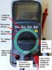
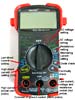
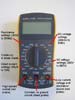
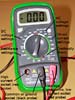
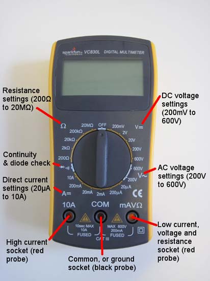
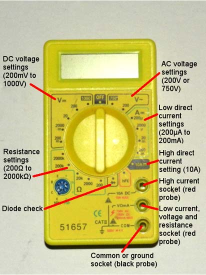
While most multimeters can perform the same basic functions, different models that are made by different manufacturers might not all look the same. In the gallery below, we have provided a series of images of different multimeters with different measurement settings and sockets for the probes labeled. Note that most of the multimeters have basic features in common, including settings for measuring voltage, current, and resistance. All of them have a single "ground" socket for the black probe. Most of them have separate sockets for measuring high and low current. The low-current socket is also used to measure voltage and resistance. However, some multimeters only have two sockets total, or only have one socket for measuring current. Some also have additional features that we did not label.
Remember, this gallery is meant to be a general guide; if you do not see your model of multimeter pictured here, your best bet is to consult your specific multimeter's manual. If you need help getting introduced to multimeters in general, refer back to our Multimeter Overview section. If you need to know how to take a specific type of measurement, refer to the Using a Multimeter section.
-
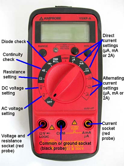
 This multimeter is a combination of auto-ranging and manual ranging. For example, it only has one setting to measure DC voltage, but it has three settings for measuring DC current. It also has one socket for measuring voltage and resistance, and another socket for measuring both high and low current. It also has a "Logic" test function for measuring digital circuits (not covered in this tutorial).
 -
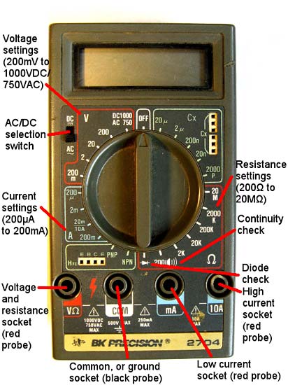
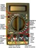 This manual-ranging multimeter has additional features capable of measuring capacitors and transistors (not covered in this tutorial). It has three separate measurement sockets: one for voltage and resistance, one for low current, and one for high current.
 -
 This multimeter us auto-ranging for voltage and resistance, but has three different current measurement settings. It has one socket to measure voltage, resistance, and small currents, and another socket to measure high current.
 -
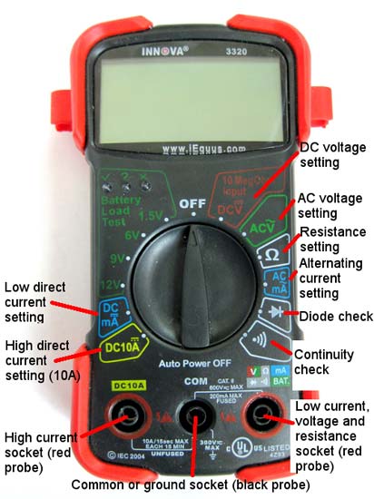
 This auto-ranging meter has a special function to test batteries. It has one socket for measuring voltage, resistance, and low current, and another socket for measuring high current.
 -
 This manual-ranging multimeter has a special function for testing transistors (not covered in this tutorial). It has one socket for measuring voltage, resistance, and low current, and a separate socket for measuring high current.
 -
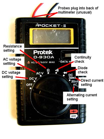
 This auto-ranging multimeter is unusual in that the probes plug in to the back side. It can only measure small currents, up to 200mA.
 -
 This is a typical manual-ranging multimeter. It has one socket for measuring voltage, resistance, and low current, and one socket for measuring high current.
 -
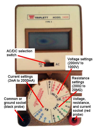
 This is an older model manual-ranging multimeter. Notice that it only has two sockets, and there is a switch to toggle between AC and DC measurements (which is unusual).
 -
 This manual-ranging multimeter has an extra feature to test transistors (not covered in this tutorial). It has one socket for measuring voltage, resistance, and low current, and another socket for measuring high current.
 -
 This is a manual-ranging multimeter with typical settings for DC voltage, current, and resistance, It can also measure AC voltage and has a continuity check. It has separate sockets for high and low current.


References
References
If you have read through this multimeter tutorial and still have unanswered questions, the references below might be helpful.
Additional references about multimeter usage:
- All About Circuits. (n.d.). Safe Meter Usage. Retrieved July 11, 2022.
- SparkFun. (n.d.). How to Use a Multimeter. Retrieved February 27, 2013.
Additional references about electricity and circuits:
- All About Circuits. (n.d.). Voltage and Current. Retrieved July 11, 2022.
- The Physics Classroom. (n.d.). Current Electricity: Chapter Outline. Retrieved February 27, 2013.
- Physics4Kids. (n.d.). Current. Retrieved February 27, 2013.
A full list of metric prefixes:
- Wikipedia contributors. (February 25, 2013). Metric Prefix. Retrieved February 28, 2013.
/-/https/img.youtube.com/vi/G5Z56fqHlw8/0.jpg)
/-/https/img.youtube.com/vi/n-gJ00GTsNg/0.jpg)
/-/https/img.youtube.com/vi/SAce4dOaGgk/0.jpg)