Abstract
Generating power from mud sounds like science fiction, but it is actually real science, and a promising source of alternative energy. Topsoil is packed with bacteria that generate electricity when placed in a microbial fuel cell. Because such bacteria-laden soil is found almost everywhere on Earth, microbial fuel cells can make clean, renewable electricity nearly anyplace around the globe. They are an up-and-coming technology that scientists and engineers are working to make even more efficient. In this science project, you will experiment with real microbial fuel cells and investigate how changing their soil conductivity by adding a dash of salt affects their power output.Summary
Svenja Lohner, PhD, Science Buddies
Thanks to Bob Rowland, ColdQuanta Inc., for assistance with testing this project, and to Ben Finio, PhD, and Howard Eglowstein, Science Buddies, as well as Keegan Cooke, Executive Director at Keego Technologies LLC, for their feedback.
/-/https/i.ytimg.com/vi/5iMw7-GIJFE/maxresdefault.jpg)
Objective
Investigate how changing the soil conductivity inside a microbial fuel cell affects its power output.
Introduction
/-/https/www.sciencebuddies.org/cdn/Files/8193/6/MFC-salt-thumbnail.jpg)
In the early 1900s, scientists showed that microbes (microscopic organisms, including bacteria) could make electricity, which is the basis of microbial fuel cell (or MFC) technology. While only a limited number of scientists researched this technology early on, more recently, as natural resources are depleted, scientists' attention has shifted to pursuing alternative energy sources, such as MFCs.
A microbial fuel cell, also known as a biological fuel cell, is a device that can use microbial interactions to generate electricity. It is a renewable, clean source of energy, and thus quite appealing. An MFC has an anode, a cathode, and an area that separates the two (called a membrane). Anodes and cathodes are both electrodes. An electrode is something that conducts electricity, with electricity either flowing into, or out of, it. An anode, specifically, has electricity flowing into it, whereas a cathode has electricity flowing out of it. So, for an MFC to function, electricity must be made to flow into the anode and then leave from the cathode. How is this accomplished?
To answer this question, we will look at MFCs that use microbes from the soil to generate electricity. When you think of electricity, and how it can be made naturally, you may think of lightning and electric eels; you probably do not think about microbes! But some soil microbes, specifically soil bacteria, can help generate electricity, too. These bacteria, known as electrogenic bacteria, include the Shewanella species, which can be found in almost any soil on Earth, and the Geobacter species, which prefer living in soil deep underground or even under the ocean, where no oxygen is present. How can these bacteria help make electricity? The soil bacteria eat what is in the soil, such as microscopic nutrients and sugars, and in turn produce electrons that are released back into the soil. Electrons are subatomic particles that have a negative electric charge. These electrons can be harnessed and used to create electricity, which is a form of energy caused by charged particles (such as electrons) flowing from a power source (such as a battery) to other components in the circuit; for example, a lightbulb. If a lightbulb is connected to a circuit that is made correctly and has enough electricity flowing through it, the lightbulb will light up. You can learn more about electricity in the Science Buddies Electricity, Magnetism, & Electromagnetism Tutorial.
In an MFC using these soil bacteria, the anode is buried in the damp soil. Down there, the bacteria multiply and cover the anode (creating a biofilm on it), supplying it with lots of electrons. At the same time, electrons are taken away from the cathode. How does this happen? While the anode is buried in the soil, the cathode sits on top of the soil, leaving one of its sides completely exposed to the air. Electrons from the anode travel up a wire to the cathode and, once there, they react with oxygen (from the air) and hydrogen (produced by the bacteria as it digests the nutrients in the soil) to create water. (The anode is buried deep enough, where there is no oxygen, so this reaction could not take place right next to the anode.) See Figure 1 for a visualization of this process. The more electron-producing, soil-munching bacteria are in the soil, the more electricity the MFC produces.
/-/https/www.sciencebuddies.org/cdn/Files/4449/15/microbial-fuel-cell-chemistry-MudWatt.jpg)
A microbial fuel cell is created from a container that is filled with soil that has a metal anode plate buried near the bottom and a metal cathode plate resting on the surface. Wires connect both the anode and cathode to a lightbulb on the lid of the fuel cell. As a biofilm made of the electrogenic bacteria Shewanella and/or Geobacter forms on the buried anode they produce electrons which are transferred from the anode to the cathode through the wires. The electrons in the cathode react with the oxygen in the air and the hydrogen in the soil to create water which goes back into the soil. When enough electrons are created by the bacteria the lightbulb will be lit.
Figure 1. This diagram shows the reactions taking place in a microbial fuel cell (or MFC) that make it generate electricity. (Wikimedia Commons, 2010, MFCGuy2010)
To evaluate the overall performance of an MFC, usually its power output is determined. This is done by measuring the voltage across a fixed resistor that you attach to the MFC and from that, power is calculated using a derivation of Ohm's law as shown in Equation 1.
Equation 1:
- P is the power in watts (W),
- V is the voltage (V), and
- R is the resistance in ohms (Ω).
If you use several different resistors, you can generate a power-resistance curve, which allows you to determine the maximum power output of your microbial fuel cell, as explained in more detail in the Procedure. The resistance at which your microbial fuel cell has its maximum power output tells you what the internal resistance of your MFC is. The internal resistance—which includes the resistance of the electrodes, the membrane, and the MFC electrolyte—indicates how much energy is lost during electricity production. It depends on many factors, such as the microbial fuel cell design, electrode spacing, the electrode size and material, or the conductivity of the electrolyte (in this case your soil). You will see that as the bacteria will start generating power from the food present in the soil, the MFC power output will start increasing over time and eventually reach a steady-state.
While scientists and engineers know how to make MFCs, they are still trying to figure out what conditions MFCs need to work the best. For example, if we add something to the soil, would it make the MFC produce electricity better, increasing the amount of power it makes? In this electricity and electronics science project, you will investigate how changing the soil conductivity changes the power output and internal resistance of an MFC by adding salt and monitoring the electrical power output. Why salt? Salt, or sodium chloride (NaCl), can be dissolved in a liquid-rich solution, such as wet soil, to create an electrolyte. An electrolyte is a liquid-rich medium that has ions, which are atoms or molecules that have an electric charge. (In the salt electrolyte, there is a positively charged sodium ion and a negatively charged chlorine ion). Consequently, if electrodes are put into an electrolyte, it can conduct electricity. (In terms of electricity, how well something can conduct electricity is related to its resistance; if something has low resistance, then electricity should easily flow through it, and it can be said to conduct electricity well, and vice versa). You will determine the conductivity of your MFC soil before and after adding salt with a simple self-made sensor and a multimeter. A multimeter is an electronic device that measures voltage, current, and resistance. You can learn more about these terms in the Science Buddies Electronics Primer. You will measure the current flowing through your soil solution by applying a voltage using a 9 volt (V) battery to supply the voltage. How this is done is described in more detail in the Procedure.
The symbol for conductivity is G and it is measured in units called siemens (S). The symbol for current is I, and it is measured in amperes (A), commonly called amps for short. The symbol for voltage is V and it is measured in volts (also abbreviated V). Calculating the conductance is easy—it is the current divided by the voltage, as shown in Equation 2.
Equation 2.
- G is conductivity, measured in siemens (S),
- I is current, measured in amperes (A), and
- V is the voltage, measured in volts (V).
Note that conductance is the inverse of resistance, which is measured in ohms (Ω, the capital Greek letter Omega). The symbol for resistance is R, so G = 1/R (1 S = 1 / Ω). Equation 2, similar to Equation 1, is just another form of Ohm's law, which uses resistance instead of conductance: V = IR. Do not worry if you find it difficult to remember all the letters and symbols. Table 1 summarizes the electrical variables, their units, and abbreviations.
| Quantity | Variable | Unit | Unit Symbol |
|---|---|---|---|
| Voltage | V | Volt | V |
| Current | I | Ampere | A |
| Resistance | R | Ohm | Ω |
| Conductance | G | Siemens | S |
What do you think will happen to the power output once you increase the soil conductivity of your MFC? You probably would expect an initial increase in the power output (as the internal resistance of the MFC decreases), but what would happen if you kept adding salt? Would the MFC continue to produce more and more power, or would it crash after a while because, perhaps, the bacteria will have died from the excess of salt? Find out yourself!
Terms and Concepts
- Microbes
- Microbial fuel cell (MFC)
- Electrode
- Anode
- Cathode
- Bacteria
- Electrons
- Electricity
- Power output
- Resistor
- Ohm's Law
- Watt (W)
- Internal resistance
- Conductivity (G)
- Electrolyte
- Ions
- Resistance, ohms (Ω)
- Multimeter
- Siemens (S)
- Amperes(A)
- Volt (V)
Questions
- How does an MFC produce power?
- What different types of MFCs are there and which types and designs do you think work best?
- How do soil bacteria help make electricity in an MFC?
- What do you think are good devices that could be powered by a microbial fuel cell?
- What factors determine the internal resistance of a microbial fuel cell?
Bibliography
These resources will give you more information about microbial fuel cells, electricity, soil conductivity:
- Logan, B. E. (n.d.). Microbial Fuel Cells and METs. The Pennsylvania State University. Retrieved November 14, 2023.
- The Physics Classroom. (n.d.). Electric Circuits. Retrieved November 14, 2023.
- United States Department of Agriculture. (n.d.). Soil Electrical Conductivity. Natural Resources Conservation Service. Retrieved November 14, 2023.
For more information about electronics terms and using a voltmeter/multimeter, use these primers:
- Science Buddies Staff. (n.d.). Electronics Primer: Introduction. Retrieved December 7, 2012.
- Science Buddies Staff. (n.d.). How to Use a Multimeter. Retrieved July 20, 2016.
Materials and Equipment 
Recommended Project Supplies
/-/https/www.sciencebuddies.org/cdn/Files/9144/29/mudd-watt.jpg)
- MudWatt Classic Kit (2), available from our partner
Home Science Tools®.
You will need these items from the two kits:
- Microbial fuel cell vessels (2)
- Anodes (2)
- Cathodes (2)
- Hacker boards (2)
- Capacitors (2)
- LEDs (2)
- Digital clock/thermometer to be powered by the microbial fuel cell (1)
- Set of 7 resistors
- Alligator clips and jumper wires (2)
- Digital multimeter (1)
- Nitrile gloves (1 pair)
- You will also need to gather these items, not included in the kit:
- Optional: Old newspapers to protect your work area
- Soil (at least 4 cups) or about 400 g of sifted soil
- Soil from just about anywhere works — from a backyard, park, open space, or even a riverbed. Just make sure the soil has not been treated with pesticides and that you have permission to take some of it.
- Soil can also be purchased from a plant nursery, a hardware store, or online. When you buy your soil, choose organic topsoil that has not been sterilized or treated with pesticides. Do not use soils with little white foam balls, vermiculite pieces, or perlite, that are used to aerate the soil, and avoid soils with peat moss.
- A sieve, plastic strainer, or colander to remove large particles from the soil
- Large mixing bowl that can hold all the soil
- Measuring cups or 100 mL graduated cylinder. A 100 mL graduated cylinder is available from Amazon.com
- Distilled water (at least 500 mL). This can be purchased at most grocery stores.
- Digital scale with 0.1 g increments; a digital scale that would be suitable is the Fast Weigh MS-500-BLK Digital Pocket Scale, available from Amazon.com
- Spoon for stirring
- Paper towel or rag
- Masking tape
- Permanent marker
- Stopwatch
- Measuring teaspoon
- Table salt (sodium chloride, NaCl)
- Transfer pipettes (at least 2), available from Amazon.com
- Disposable plastic straw
- Mini plastic cups with lids, 3 oz, like you would get condiments in at a restaurant (at least 6)
- Copper wire, bare, 24-gauge (1.5 meters [5 feet])
- 9 V battery
- 9 V battery clip (snap connector), available from Jameco
- Scissors
- Lab notebook
Disclaimer: Science Buddies participates in affiliate programs with Home Science Tools®, Amazon.com, Carolina Biological, and Jameco Electronics. Proceeds from the affiliate programs help support Science Buddies, a 501(c)(3) public charity, and keep our resources free for everyone. Our top priority is student learning. If you have any comments (positive or negative) related to purchases you've made for science projects from recommendations on our site, please let us know. Write to us at [email protected].
Experimental Procedure
Working with microbial fuel cells involves growing soil bacteria. Because of this, many science fairs, including those associated with the International Science and Engineering Fair (ISEF) have requirements which need to be met before you start your project. We recommend you:
- Check with your teacher or science fair coordinator about any requirements
- Read the Science Buddies Microorganisms Safety Guide to learn how to safely handle bacteria
Setting up the Microbial Fuel Cells
You will assemble two identical microbial fuel cells that contain the same soil material. Later in the procedure, you will add a different amount of table salt to each one of them and compare their power outputs. Do you think more salt results in more power?
- First, watch the video or follow the step-by-step instructions to see how to assemble the microbial fuel cells.
- Prepare your soil mud.
- Place a plastic strainer or colander over a large mixing bowl.
- Measure a total of about 2 cups (about 500 milliliters [mL]) of your soil for each of the microbial fuel cells into the strainer (4 cups in total). Gently shake the strainer over the bowl so that the soil is strained and any small, hard particles (such as rocks, pebbles, twigs, etcetera) are removed from the soil. You will likely need to be patient; it may take several minutes to strain the soil. When you are done, you should have about 400 g of fine, sifted soil in the bowl.
- It is important to remove these particles from the soil because they can aerate the soil and inhibit the desired bacteria from growing (the bacteria do not want to be exposed to oxygen).
- Add distilled water and mix it in until your topsoil mud feels like cookie dough. Add more water if the mud is too crumbly, or add more topsoil if the mixture feels too wet.
- When you have prepared your topsoil mud, set it aside and wash your hands.
- With a teaspoon, take a sample of your prepared soil (about 3 g) for initial conductivity measurements. Label a mini cup with the date and time, and use the teaspoon to scoop about 1–2 spoons full of your prepared soil (you will need 1 g) into the cup. Put the lid on the mini cup and set it aside for now.
- Carefully take the MFC pieces out of the box and lay them out. Identify the different components and use masking tape and a permanent marker to label one of the devices with "1 g salt" and the other one with "5 g salt".
- Put on the gloves that came with the MFCs and start assembling the first microbial fuel cell.
- Take out the green and orange wires that came with the MFC electrodes. Bend each wire where the plastic part ends so that each wire is now at a 90° angle (shaped like a capital "L"), as shown in the video above.
- Remove the MFC anode from its bag (the anode is the thinner, black, felt-like circle).
- Safety Note: The MFC's cathode and anode (its electrodes) are made of a conductive material called graphite fiber. Do not put the cathode or anode near electronics or power plugs, and do not disperse the fibers in the air, as the fibers will cause electrical shortages when in contact with electronics.
- Straighten the metal part of the green wire and carefully insert it into the anode, as shown in Figure 2. Make sure the wire goes straight and does not poke out on the top or bottom sides of the anode.
/-/https/www.sciencebuddies.org/cdn/Files/6597/27/wire-in-anode.jpg)
Figure 2. Insert the metal part of the green wire into the anode circle.
- Repeat steps 6 and 7 using the cathode (the thicker, black, felt-like circle) and the orange wire (which is shorter than the green wire).
- Take the soil mud that you prepared in step 2 and use it to fill the first vessel up to the line next to the "1" on the plastic vessel (marking 1 centimeter [cm]). Once filled, pat the mud so that its surface is smooth.
- Tip: You may want to cover the surface you are working on with old newspapers to prevent mud from getting on it.
- When you are finished, rinse the mud off your gloves and dry them (but do not take them off yet).
- Put the anode on top of the mud in the vessel, as shown in Figure 3.
- The green wire from the anode should be sticking up. The green wire should not be stuck down in the mud.
- Gently press the anode flat against the mud so that no air bubbles are under the anode. Note: Removing the air bubbles is important, as the trapped oxygen can prevent the formation of an anaerobic bacterial biofilm and reduce the power output of your microbial fuel cell.
/-/https/www.sciencebuddies.org/cdn/Files/6601/26/anode-in.jpg)
Figure 3. Place the anode on top of the 1 cm of mud.
- Use more soil mud to fill the vessel up to the line next to the "5" mark (marking 5 cm). Once filled, again pat the mud so that its surface is smooth.
- Run the green wire along the side of the vessel.
- Rinse the mud off your gloves and dry them.
- Gently place the cathode on top of the mud and press it as flat as you can, as shown in Figure 4.
- The orange wire from the cathode should be sticking out of the top side.
- Do not let any mud or liquid cover the top of the cathode.
- It is best to arrange the cathode so that its orange wire is about 1–2 cm to the left of the green wire.
- Let the mud rest in the vessel for a few minutes. Then carefully pour off any excess liquid.
/-/https/www.sciencebuddies.org/cdn/Files/6603/26/cathode-in.jpg)
Figure 4. Add the cathode on top of the 5 cm of mud.
- Use a clean paper towel or rag to wipe any mud off the vessel's rim. Then take off your gloves.
- Take the white plastic lid and pass the wires through the small holes in the lid. Arrange the wires so that the orange wire is on the left and the green wire is on the right when the semicircular indentation on the lid is facing the front. Then carefully snap the lid onto the plastic vessel.
- Take out the hacker board (the small green circuit). Attach it into the lid's rectangular indentation.
- Locate the "+" and "-" ports (the holes) on the hacker board. Plug the cathode's wire (orange) into the "+" port and the anode's wire (green) into the "-" port.
- Locate ports 1 and 2 on the hacker board. Plug the blue capacitor (the small, cylindrical item with two longer metal prongs) into these ports. The blue capacitor's longer prong should go into port 1 and the shorter prong into port 2. Note: The orientation of the capacitor is important. If you reverse the short and long prongs, it will not work and might even damage the capacitor. You may need to bend the capacitor's longer end slightly so that the capacitor's prongs fit into the ports well.
- Plug the red LED below the capacitor into ports 5 and 6 (ports 3 and 4 will remain empty). The LED's longer prong should go into port 5 and the shorter prong into port 6. Note: The LED will only work if inserted in this orientation. If you accidentally reverse the prongs, the LED will not light up. You may need to bend the LED's longer end slightly so that the LED's prongs fit into the ports well.
- Make sure that the wires, capacitor, and LED are all securely in place. The assembled hacker board on the top of the MFC should now look like Figure 5.
/-/https/www.sciencebuddies.org/cdn/Files/6607/31/microbial-fuel-cell-closeup.jpg)
Figure 5. When you have finished assembling your MFC and its hacker board, the top should look like the one in this image.
- After assembling the first MFC, set up the second microbial fuel cell using the rest of the prepared soil from step 2.
- Once both microbial fuel cells are assembled, set the MFCs indoors, at normal room temperature (about 19–25° Celsius [C], or 66–77° Fahrenheit [F]), in a place where they will not be disturbed. The MFCs should remain in the same location the entire time after you set them up because if they are moved this could disrupt the growth of the bacteria. It should take 3–7 days before the red LEDs on the hacker board start blinking, but you will start taking measurements before that, as described in the sections below. Note: Temperature variations can cause changes in the power output of the microbial fuel cells due to different bacteria activities.
Measuring Soil Conductivity
- First, you will make a simple conductivity sensor.
- Using the scissors, cut a 5 cm (2 inch) piece from the drinking straw and two pieces of copper wire, each about 12 cm (5 inches) long.
- Assemble the conductivity sensor, as shown in Figure 6.
- Wrap one piece of wire around the 5 cm straw piece near one end a few times, leaving a 5 cm (2 inch) tail of wire. Make sure you wrap the wire snugly around the straw. If the wires on the conductivity sensor move while you are taking measurements, your measurements may be inaccurate.
- Wrap the second piece of wire around the other end of the straw tube a few times, leaving a 5 cm (2 inch) tail of wire. There should be no contact between the two pieces of wire, and they should be wrapped tightly enough that they will not slide off the straw.
- Caution: Make sure the two wires do not touch. The conductivity sensor will not work if the wires touch, and touching wires will blow the fuse in your multimeter.
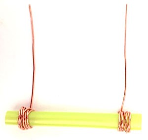
Figure 6. The conductivity sensor consists of a non-conducting core (a piece of disposable drinking straw) with copper wire wrapped around the ends. The ions in the solution complete the circuit, enabling current to flow between the copper wires.
- Next, you will make the conductivity measuring circuit using the multimeter that comes with the Microbial Fuel Cell kit. If you need help using a multimeter, consult the Science Buddies reference
How to Use a Multimeter,
as well as the instructions that came with your multimeter. Figure 7 shows a detailed picture of the entire circuit. If you want, you can assemble your circuit just by looking at this figure. Otherwise, read the following detailed steps and refer to the figure as needed.
- Connect the snap connector to the 9 V battery.
- Make sure the multimeter is switched off and plug the multimeter probes into the multimeter. The black (negative) probe goes in the port labeled "COM" at the bottom right of the multimeter. The red (positive) probe goes in the middle port, labeled "VΩMA."
- Clip the alligator clip at the end of the red multimeter lead to the exposed metal part of the positive (red) wire of the 9 V battery snap connector.
- Attach one of the copper wire tails of the conductivity sensor to the negative (black) probe of the multimeter lead using the alligator clip.
- Twist the other wire tail of the conductivity sensor around the metal end of the black lead from the 9 V battery snap connector. Important: It is essential that you twist these wires together tightly, so they do not come loose. If the wires do not make good, consistent contact with each other, the circuit will not be complete and your experiment will not work. Make sure these wires do not get disconnected if they are bumped or moved during your experiment. If you have a pair of pliers, you can use them to squeeze or "crimp" the wires together and that will help them stay connected.
- Double-check your connections to make sure they match those shown in Figures 7. The order of the connections is important!
- Note that this is an open circuit because of the gap between the wires wrapped around the (non-conducting) straw. You will use the electrolytes or ions in the soil solution to close the circuit. The amount of current that flows is proportional to the electrolyte concentration.
- Important: Never let exposed metal from the red or black multimeter probes/alligator clips, or the conductance sensor wires, touch each other directly. This will create a short circuit. Since the circuit contains a 9 V battery, this could damage your multimeter by blowing out the fuse. Always keep the red and black wires a safe distance away from each other, as shown in Figure 7. Keeping your multimeter's dial in the "OFF" position when not in use will also help prevent accidental damage to your multimeter.
/-/https/www.sciencebuddies.org/cdn/Files/8011/11/conductivity-sensor.jpg)
/-/https/i.ytimg.com/vi/ts0EVc9vXcs/maxresdefault.jpg)
/-/https/www.sciencebuddies.org/cdn/Files/8012/10/conductivity-circuit.jpg)
Figure 7. This photo shows an example of the completed conductivity measuring circuit.
- Finally, prepare your soil sample and measure its conductivity.
- Take two clean mini cups and fill both with 20 mL of distilled water. You can use the digital scale to add water to the cups until each weighs 20 g.
- From your set-aside soil sample, add 1 g to one of the cups with 20 mL of distilled water and stir with a clean spoon.
- Set your multimeter to measure direct current in the 2000 µA range on the upper-right part of your multimeter dial. This is a high-sensitivity setting that you will only use to measure solutions with low conductivity, such as distilled water.
- Place the conductivity sensor in the distilled water. Make sure the straw is completely immersed and read the current on the multimeter. Note: Your readings may fluctuate slightly, and this is normal. Try to record an "average" reading, or a number in the middle of the range that you observe. Make sure to record that this reading is in microamps (µA). Remember that a microamp is one millionth of an amp.
- You do not need to rinse your conductance sensor this time because you used distilled water.
- Now set your multimeter to measure direct current in the 20 mA range on the right side of the multimeter dial. This setting can measure higher current values, which you need to do for more conductive liquids, such as your soil sample.
- Now place the conductivity sensor in the cup with your soil solution and record the current. Again, make sure you record the correct units. If your multimeter dial is set to 20m, this reading is in milliamps (mA), not microamps (μA). Note: Depending on your soil, you might need to keep your multimeter set to the 2000 µA setting.
- Tap the sensor on a paper towel to remove drops of the soil solution. Then rinse the sensor in distilled water.
- Repeat the conductivity measurements for both solutions—the distilled water and the soil—two more times to obtain a total of three measurements for each liquid. Remember that you will need to switch back and forth between the "2000μA" and "20 mA" setting depending on the solution you are measuring.
- Record all data and measurements, including the proper units, in a data table in your lab notebook.
Measuring Power Output and Adding Salt
You will measure the power output for both of your microbial fuel cells every day. Once the power output seems to have stabilized, you will add a a different amount of table salt to each one of the microbial fuel cells. The salt should change the power output of the MFC. How do you think the MFC's power output will be affected?
- One day after setting up your microbial fuel cells, check to see if the LEDs are blinking. Most likely, they will not be, but check to make sure. Watch the LEDs for 2 minutes to see if they are blinking.
- If one or both of the LEDs are blinking, time how many seconds apart the blinks for each one are.
- To do this, start a stopwatch as soon as you see the LED blink and stop the stopwatch when the LED blinks again.
- If the LED is blinking faster than once every 5 seconds, do not time the seconds between blinks, but instead time the blinks per second. Time a 10-second interval and count how many times the LED blinks in this period and then divide this by 10 to get blinks per second.
- Repeat step 1.a.i. or 1.a.ii. two more times so you have a total of three counts.
- Record your results for each MFC in your lab notebook in a data table like Table 2. (If you counted blinks per second, as in step 1.a.ii., change the heading from "Seconds Between Blinks" to "Blinks per Second.") Calculate the average for your three counts and record that, too.
- If one or both of the LEDs are blinking, time how many seconds apart the blinks for each one are.
| Seconds Between Blinks | ||||
|---|---|---|---|---|
| Day | Count #1 | Count #2 | Count #3 | Average |
| 1 | ||||
| 2 | ||||
| 3 | ||||
- Next, measure the power output for both of the MFCs using the same multimeter as for your conductivity measurement circuit. You can either watch the video below or follow the step-by-step instructions.
- To measure the MFC's power output, remove the capacitor and LED from the hacker board. Then remove the orange wire from the "+" port and plug it into port 3. This means that the orange wire should be in port 3, the green wire should still be in the "-" port, and all other ports should be empty.
- Place a resistor between ports 5 and 6, as shown in the video above. For the resistors, the orientation does not matter.
- Several resistors come in the MFC kit; start with the largest-capacity resistor, which will be a 4.7 kΩ resistor. (Ω, the capital Greek letter Omega, is the symbol for ohms, the unit used to measure resistance. 1 kilo-ohm, or 1 kΩ, is 1000 ohms.)
- Resistors' values are labeled using color-coded bands. Use Figure 8 to determine the resistance for each resistor.
- Tip: If you want, you can confirm the resistance of any resistor using your multimeter by setting it to measure resistance (usually a "Ω" symbol for ohms) and connecting the multimeter's leads on the wire ends of the resistor.

Figure 8. Use this resistor color chart to determine the resistance for each resistor.
- Leave the resistor plugged in for 5 minutes.
- After the resistor has been plugged in for 5 minutes, use your multimeter to measure the voltage across the resistor.
- Make sure the multimeter's black wire is plugged into the "COM" port and its red wire is plugged into the "VΩMA" port on the multimeter.
- Set the multimeter to measure DC voltage. This is marked as "V" with a straight line next to it. Specifically, turn the dial to "2000 m."
- Clip the multimeter's red lead to the resistor's metal wire that is plugged into port 5. Then clip the multimeter's black lead to the resistor's metal wire that is plugged into port 6, as shown in the video. Read the multimeter's screen to see what the voltage is (in millivolts [mV]).
- If the voltage seems to be changing a little, such as decreasing slightly over the period of a few seconds, watch the readings on the multimeter for a few seconds more until they stabilize (and stay the same for a few seconds). Use the stabilized value.
- If the readings are still changing after several seconds, or if your readings are 0 mV, make sure all of the wires are correctly and securely plugged into the circuit (both the cathode and anode wires, and the resistor's wires), disconnect the multimeter's leads from the resistor, and come back in another 5 minutes. Then repeat step 2.c.
- Record your results for both of the microbial fuel cells in your lab notebook in a data table like Table 3.
Table 3. In your lab notebook each day, create a data table like this one for each microbial fuel cell to record your voltage measurements. Do not forget to write down the date and the time you started taking measurements on the top line.Day and Time: Resistance (ohms) Voltage (mV) Power (μW) 4700 2200 1000 470 220 100 47
- Disconnect the multimeter's clips from the resistor. Remove the resistor.
- Repeat steps 2.b.–2.d. until you have tested the MFC with all of the resistors in the kit. Start with the resistor with the largest resistance value and end with the resistor with the smallest resistance value.
- Once you have finished taking your voltage measurements for the first MFC, plug the wires, the capacitor, and LED back into the hacker board, as described in steps 16–18 in the Setting Up the Microbial Fuel Cells section above and repeat the voltage sweep (steps 2 and 3) for the second microbial fuel cell.
- Calculate the power output (in microwatts, or µW) for each resistor and both microbial fuel cells. You can calculate this by using a derivation of Ohm's law, as described in the Introduction, Equation 1.
- Note: It is important to convert the voltage measurements into power output measurements. The power output depends on the resistors you use, so you cannot determine how well the MFC is performing by just looking at the voltage measurements alone; they need to be converted into power for them to be meaningful.
- To use Equation 1, you will need to convert your voltage readings from millivolts (mV) to volts (V). To do this, divide the millivolt values by 1000 to give you volts.
- For example, if you had a voltage reading of 45 mV, this would equal 0.045 V.
- Using Equation 1, your answer will be in watts (W). Convert watts to microwatts by multiplying your answer by 1,000,000.
- Once you have calculated it, record the power for each resistor in the data table (such as Table 3) in your lab notebook.
- Determine what the peak power of your MFCs is.
- In your data tables for both microbial fuel cells, look at the power produced using each resistor. The peak power is the highest power produced by any of the resistors.
- If you want to visualize this, you can plot your data for the day on a graph, putting the resistance of the resistors on the x-axis (horizontal axis) and the power on the y-axis (vertical axis) for both MFCs. A sample graph is shown in Figure 9.
- You should see a curve, with the peak power at the top of the curve, as shown in the sample graph.
- Make a note in your lab notebook of what the peak power for both MFCs is each day, by circling or highlighting this value in your data table. Do these values change over time? Why do you think might this be the case? Remember that the peak power tells you what the internal resistance of your MFC is.
/-/https/i.ytimg.com/vi/p2q6BGJuxRk/maxresdefault.jpg)
/-/https/www.sciencebuddies.org/cdn/Files/7978/20/resistor-chart.png)
/-/https/www.sciencebuddies.org/cdn/Files/6608/6/resistance-power-output-sample-graph.png)
The sample graph shows six points of data that appear to follow a pattern of increased power output when resistance is increased. The pattern applies up to the peak output of about 45.5 microwatts using a 1000 ohm resistor. Power output gradually decreases in the two following data points to about 43.5 and 33 microwatts at 2200 and 4700 ohms respectively.
Figure 9. This sample graph shows possible power output data using the resistors with the MFC. In this sample, the peak power was found using a 1 kΩ resistor, and the peak power is about 45.5 μW.
- Repeat steps 1–5 each day until it looks like the power output (the peak power) for both of your microbial fuel cells is stabilizing.
- Take these measurements around the same time every day. This will limit variables affecting your results (such as changes in temperature).
- For step 1, it should take 3–7 days for the LEDs to start blinking. However, even if the LEDs never blink, you may still be able to do this science project; be sure to continue to take the power output measurements every day.
- Tip: See the Frequently Asked Questions section for what to do if the LEDs do not blink, or if they were blinking and unexpectedly stopped blinking.
- For step 2, you should see the power output slowly increase.
- For each day, make a data table like Table 3, for each MFC in your lab notebook to record your results and use them to determine the peak power.
- After about 7–14 days, the power output should stabilize.
- It may stabilize anywhere between 10 μW to 200 μW or more. A lot depends on the topsoil you are using and other factors. Wherever it stabilizes, it should make enough power to for the LED to blink at least once every 30 seconds.
- Tip: If the power output seems low, see the Frequently Asked Questions section for suggestions on what to check and try.
- When it stabilizes, the peak power should not change by more than about 10% for at least three days in a row.
- Do not worry if your peak power changes by a little more than this. If it has been at least 14 days and when you graph the peak power (as described in step 6.d.iii., following) it looks like it is stabilizing (meaning it is not steadily increasing or steadily decreasing from day to day), then it has probably stabilized enough.
- Keeping this in mind, if it still does not look like your peak power is stabilizing, see the Frequently Asked Questions section for suggestions on what to check and try.
- Tip: Making graphs of your data as you collect it for both MFCs may help you see if the power output is stabilizing. If you do this, put the date on the x-axis and the power output (peak power) for each day on the y-axis. Does the peak power appear to be stabilizing?
- The time between LED blinks should also stabilize.
- It may stabilize anywhere between 10 μW to 200 μW or more. A lot depends on the topsoil you are using and other factors. Wherever it stabilizes, it should make enough power to for the LED to blink at least once every 30 seconds.
- Once it appears that the power output has stabilized in both MFCs, carefully open up both microbial fuel cells and add 1 g salt to the one you labeled "1 g salt" and 5 g salt to the one you labeled "5 g salt".
- Take your measurements for the day as usual before starting the treatments.
- On the digital scale, weigh 1 g of table salt (NaCl) into a mini cup and add 5 mL of distilled water. Mix to dissolve the salt completely.
- In another mini cup add 5 g of table salt to 5 mL distilled water. Again, mix until the salt is completely dissolved.
- Unplug the anode and cathode from the hacker board and carefully remove the lid of the first microbial fuel cell which you labeled "1 g salt."
- Put your gloves on and gently lift up the cathode, being careful not to get any mud on top of the cathode.
- Safety Note: Remember, the MFC's electrodes are made of a conductive material called graphite fiber. Do not put the cathode near electronics or power plugs, and do not disperse the fibers in the air, as the fibers will cause electrical shortages when they come in contact with electronics.
- Take a clean spoon and use it to dig into the top 1–2 cm of the soil. Be careful not to dig all the way down to the anode as this disturbs the anode biofilm. Then use a clean transfer pipette to suck up some salt solution from the cup with 1 g salt and spread it on top of the mud, mix it in, and then dig around inside of the mud, adding all of the salt solution and mixing it in as you go. You want to mix the salt as evenly into the mud as possible, but do not disturb the anode —leave it in place (as well as its wire and the mud below the anode)
- Once you mixed the all salt in, scoop about 1 teaspoon of soil (about 1–2 g) into a fresh mini cup, labeled with time, date and microbial fuel cell type (1 or 5 g of salt) for the conductivity measurement. Flatten the mud surface with a spoon again before you re-assemble the MFC.
- Then assemble the MFC exactly as you put it together before, following the instructions from the previous "Setting Up the Microbial Fuel Cells" section to make sure that the wires are twisted together properly and everything is reconnected to the hacker board correctly.
- Specifically, this will be following steps 16–18 from the Setting Up the Microbial Fuel Cells section.
- Do not get any mud on the top of the cathode. If you do, carefully wipe it off, being careful not to grind it into the cathode.
- Repeat step 7 with the "5 g salt" microbial fuel cell, but this time add the salt solution with 5 g of salt.
- Set up and use the conductivity measurement circuit again to measure the soil conductivity in both of your microbial fuel cell soil samples after adding the salt, as described in the previous Measuring Soil Conductivity section. Record the new conductivity values in your lab notebook.
- Starting the day after you add the salt, continue monitoring the power output of both microbial fuel cells by repeating steps 1–5 each day until it looks like the power output (the peak power) of both microbial fuel cells is stable again (as described in step 6). Shortly after it stabilizes, the power output may then clearly change again.
- Take these measurements at the same time every day.
- For each day, for each MFC make a data table like Table 3, above, in your lab notebook to record your results and use them to determine the peak power. Note: It is possible that the resistor you use to determine the peak power will change slightly. Make a note of this in your lab notebook if it happens.
- Depending on the exact conditions of your experiment—which can be affected by the soil you use—the power output could take anywhere from several days to over a week to stabilize after adding the salt.
- When the power output is stabilized, the peak power may not change by more than about 10% for at least three days in a row. How much the power varies when it is "stabilized" can depend on the amount of power being produced by the MFC.
- Overall, if it has been about two weeks after adding the salt and the peak power has not been steadily decreasing or increasing each day for at least the last week, then it has probably stabilized enough.
- After it has stabilized, the power output may then clearly change again (steadily decreasing or increasing each day).
- Tip: Making a graph of your data as you collect it for each MFC may help you see if the power output is stabilizing. If you do this, put the days on the x-axis and the power output (peak power) on the y-axis. Does the peak power appear to be stabilizing?
- The time between LED blinks should also stabilize.
Analyzing Your Results
- Make two graphs of your data for each microbial fuel cell, one showing how the power output changed over time and one showing how the frequency of LED blinks changed over time.
- For the graph showing power output over time, put the number of days after setting up the MFC on the x-axis and the peak power output (in µW) on the y-axis.
- For the graph showing the frequency of LED blinks over time, put the number of days after setting up the MFC on the x-axis and the blinks per second on the y-axis.
- If you recorded the time between blinks in your data table, convert this to blinks per second by taking the data for the average seconds between blinks that you collected each day and calculate what 1 divided by this number is. For example, if your LED blinked an average of once every 15 seconds, 1 divided by 15 is 0.067, which is the number of blinks per second it made.
- Analyze your graphs.
- Locate the day that you added the salt. What happened in both microbial fuel cells to the power output and frequency of the LED blinks the day after adding salt? How quickly did these measurements stabilize? When they stabilized, were they higher or lower than they were originally, before adding salt?
- When was the power output and blinking frequency the highest? What was the peak power at this time? Did the MFC with 5 g salt addition perform better or worse compared to the 1 g salt addition? Why do you think this is the case?
- What do you think would happen if you added even more salt? Why?
- Did you see many differences in how the power output changed versus how the frequency of blinks changed? Why do you think this might be? Which measurement do you think is more accurate? Why? If you want to explore this relationship further, see the Make It Your Own section.
- Look back into each data table for your voltage sweeps to identify the highlighted resistor values that resulted in the peak power output for each microbial fuel cell. Make a data table for each MFC in which you record this highlighted resistance value (in Ω) for each day. Again, mark the day that you added the salt to your MFCs. The resistor you use to find the peak power tells you what the internal resistance of the MFC is. If you have to use different resistors over time to find the peak power, this means that the internal resistance of the MFC is shifting. You can visualize your data by creating a graph that shows the number of days on the x-axis and the resistance values on the y-axis for both MFCs. Do you see a shift happening throughout the experiment? When and why did this shift happen? What does this tell you about the internal resistance within both of the MFCs? Do you see a correlation with anything, such as a shift after adding more salt or a change in the power output? Hint: Re-read the Introduction and research internal resistance and electrolytes to try and figure this out. You may want to use additional resistors to narrow down the internal resistance of the MFC, as described in the Make It Your Own section.
- Compare your soil conductivity readings before and after adding salt.
- First, average your current measurements for each microbial fuel cell across the three trials. Before you proceed, convert all of your current measurements to amps (A).
- Convert microamps (μA) to amps (A) by dividing by 1,000,000. For example, 20 microamps is 0.00002 amps (20/1,000,000 = 0.00002).
- Convert milliamps (mA) to amps (A) by dividing by 1,000. For example, 20 milliamps is 0.02 amps (20/1,000 = 0.02).
- Calculate the conductivity for each liquid by using Equation 2 from the Introduction.
- The current (I) for each solution is the average current that you calculated. Make sure you convert the current to amps. Do not use milliamps or microamps in Equation 2.
- Since the voltage was always from your 9 V battery, you can use 9 V as the voltage (V) in your calculations.
- Compare the soil conductivities to the maximum power output once the microbial fuel cells stabilized. Do you see any correlation? You can make a bar graph for both MFCs showing the soil conductivity before and after adding salt on the x-axis and the corresponding maximum power output on the y-axis.
- Did you find that more salt resulted in more power or did you destroy the bacteria by adding too much salt?
- First, average your current measurements for each microbial fuel cell across the three trials. Before you proceed, convert all of your current measurements to amps (A).
Troubleshooting
For troubleshooting tips, please read our FAQ: Spice Up the Power of a Microbial Fuel Cell with a Dash of Salt.
Ask an Expert
Global Goals
The United Nations Sustainable Development Goals (UNSDGs) are a blueprint to achieve a better and more sustainable future for all.
/-/https/www.sciencebuddies.org/cdn/Files/19750/5/E-WEB-Goal-07.png)
Variations
- In this science project you measured both, the LED blinks per second and the power output using the MFC, but you did not extensively analyze how those two types of measurements correlate with each other. Go through some of your data and create a graph showing power output (in µW) on the x-axis and blinks per second on the y-axis. How does the power output correlate with the blinks per second? Is there a linear relationship, or something else? Are there some points at which the relationship does not seem to work, such as at very low or very high power outputs? Why do you think this is?
- If you want a more challenging way to explore this relationship further, try using a power supply with the MFC hacker board and two multimeters. Have someone very experienced with electronics help you hook up the power supply with the hacker board and the multimeters, arranging it so that one multimeter measures the voltage from the power supply and the second multimeter measures the current. Knowing the voltage and current, you can use the following Equation 3 to calculate the power going into the hacker board. What is the relationship between the frequency of LED blinks and the power supplied? Is there a minimum amount of voltage needed to make the LED blink? Why do you think this is? How does this data correlate with the data you collected using the MFC to power the hacker board?
- Safety Note: Adult supervision is recommended when using of the power supply, as it can cause serious harm to the hacker board and user if used incorrectly.
- Note To prevent damaging the hacker board, we recommended you test it with no greater than 0.75 V.
- Tip: The hacker board has a voltage-boosting chip (the tiny black rectangle in-between the circular testing pads). This chip "up-converts" the voltage the hacker board receives into short bursts to make the LED blink. Additional information about the chip can be found at Digi-Key® Corporation.
- If you want a more challenging way to explore this relationship further, try using a power supply with the MFC hacker board and two multimeters. Have someone very experienced with electronics help you hook up the power supply with the hacker board and the multimeters, arranging it so that one multimeter measures the voltage from the power supply and the second multimeter measures the current. Knowing the voltage and current, you can use the following Equation 3 to calculate the power going into the hacker board. What is the relationship between the frequency of LED blinks and the power supplied? Is there a minimum amount of voltage needed to make the LED blink? Why do you think this is? How does this data correlate with the data you collected using the MFC to power the hacker board?
Equation 3:
- P is the power in watts (W),
- V is the voltage (V), and
- I is the current in amperes (amps, or A).
- The MFC in the Science Buddies kit normally powers a red blinking LED light, but it could power other electronic devices, such as the digital clock (also provided in the Microbial Fuel Cell kit), if it produces enough power for them. Investigate what other electronic device(s) could be powered using the amount of voltage and current produced by your MFC, then test whether it can power the device(s). Does it work? How much more voltage and current would you need to power other devices? Knowing that you can hook multiple MFCs together to make more power, how many MFCs would you need to power larger electronic devices, such as a television or a computer? Does it make a difference if you connect both microbial fuel cells in parallel or in series? Why?
- In this science project you used different resistors to figure out the peak power made by the MFC, but you were limited by the resistors supplied in the MFC kit. You could repeat this project, using additional resistors, to more closely figure out what the peak power is. For example, if you used the 100 ohm, 220 ohm, and 470 ohm resistors from the kit and found the peak power when using the 220 ohm resistor, this tells you that the peak power is somewhere between 100 ohms and 470 ohms, but it may not be exactly at 220 ohms—this is just the closest resistor you had available. You could use additional resistors that fall within this range (100 ohms–470 ohms) to more closely find the peak power. On the other hand, if you found that the peak power could be produced using resistors greater than the ones supplied in the Science Buddies MFC kit, you can use larger resistors to test this. Is the actual peak power significantly different than what it was using the resistors in the kit?
- To use additional resistors, you can either find an electronics specialist who might let you use some of his or her resistors, or you can purchase them online as a kit from SparkFun Electronics® or individually at a company such as Digi-Key. (The type of resistors you want are "Through Hole Resistors," with power of 0.25W and a composition of metal film. Note: If you order resistors from Digi-Key, some may need to be purchased in large quantities; check the minimum quantity needed after selecting the resistor you want to purchase.)
- Alternatively, you can try to use the resistors in the kit to narrow down the peak power. Connecting the resistors in series (connecting the resistors to each other) will increase the total resistance, but this can be challenging to do successfully. Connecting the resistors in parallel (turning on two resistors) will decrease the resistance. If you want to try this, research more about how to do it.
- As yet another alternative, you can use a device called a potentiometer to narrow down the peak power (although fixed resistors may work better with the MFC). Look into potentiometers to figure out how to use one this way.
- You can also use this project to investigate different natural soil conductivities. How do these vary in the environment? Where could you find soils that are rich in electrolytes and ions, which would conduct electricity very well in a microbial fuel cell versus soil that has a very low conductivity? Search for different soils that you think have very different conductivities. Will you find that one outperforms the other in a microbial fuel cell? Why do you think this might be the case? Keep in mind that the soil conductivity is not the only factor that affects the power output of an MFC. The most important criteria is the presence of enough electrogenic bacteria. For more details, see the Science Buddies project Turn Mud into Energy With a Microbial Fuel Cell.
- Can you think of other means to change the internal resistance of a microbial fuel cell besides increasing or decreasing the soil conductivity? What about changing the distance between the electrodes? Does it matter if the electrodes are spaced 4 cm apart or less? Repeat this experiment, but this time, vary the electrode spacing in both MFCs. You can leave the anode at the 1 cm level, but place the cathode at the 3, 4, 5, or 6 cm level inside the vessel. What do you think will happen if you put the electrodes closer together?
- For additional ideas focusing on the biological aspects of the microbial fuel cell, see the Science Buddies science projects Using Urine in a Microbial Fuel Cell and How Do Bacteria Produce Power in a Microbial Fuel Cell?.
Frequently Asked Questions (FAQ)
/-/https/www.sciencebuddies.org/cdn/Files/8190/19/flowchart-setup-microbial-fuel-cell.png)
A flow chart seperates a microbial fuel cell experiment into 3 time ranges and provides a diagnosis for 3 problems that may occur during the experiment. The first section covers days 3-7 of the experiment and asks "does the LED blink?". If it does not blink 5 steps are given to solve the issue, if the LED does not blink after 14 days the experiment is restarted. The second section covers days 7-14 and asks "is the power output stable? (changes less than 10% over 3 days)". If power output is not stable 4 steps are given to solve the issue, if the output remains unstable by day 21 the experiment is restarted. The last section is identical to the previous section except it covers all days after day 21 and after the treatment of the fuel cell.
Figure 10. Flow chart for troubleshooting the microbial fuel cell experiments.
- If the hacker board is not set up correctly, the LED will not blink. You should confirm that everything is set up as described in the Setting Up the Microbial Fuel Cells section of the Procedure.
- The LED might not have enough power to blink. You will need a peak power output of at least 4 µW before the LED starts to blink, and the initial blinking may only be about once every 30 seconds, so you will need to closely watch the LED to see it blink.
- Depending on the type of topsoil you are using, it may take about 3–7 days for the LED to start blinking, if everything is properly in place. Some types of topsoil might make the microbial fuel cell take longer to blink than other types of topsoil because it may take longer for enough power to be made to light up the LED. Make sure that you are not using any topsoil with little white foam balls, vermiculite pieces, or perlite, since these can aerate the soil and inhibit the desired bacteria from growing (they do not want to be exposed to oxygen). Also avoid types of topsoil with peat moss or topsoil that has become completely dry.
- The temperature of the room that the microbial fuel cell is in can significantly affect how well the bacteria grow, which affects whether (and how quickly) the LED blinks. The microbial fuel cell should be kept indoors, at normal room temperatures (about 19–25° Celsius [C], or 66–77° Fahrenheit [F]), in the same location the entire time after you set it up. If the room gets too cold, the bacteria may not grow well. If the microbial fuel cell is moved to a different location, this could disrupt the growth of the bacteria.
- Even if the hacker board is set up correctly, some of the wires might be loose or may not be making good electrical contacts in the hacker board. You can try taking the wires out of the microbial fuel cell and then putting them back into the correct positions, and/or gently jiggling the wires around in the slots in the hacker board. Also make sure that none of the exposed parts of the wires are touching each other.
- It the LED has become damaged. You can check to make sure the LED is working by hooking it up to a battery, as shown in Figure 5 of this science project idea: Making a Cell Phone Spectrophotometer.
- If the hacker board is not set up correctly, it will not produce power. You should confirm that everything is set up as described in the Setting Up the Microbial Fuel Cells section of the Procedure.
- Even if the hacker board is set up correctly, some of the wires might be loose or may not be making good electrical contacts in the hacker board. You can try taking the wires out of the microbial fuel cell and then putting them back into the correct positions. Also make sure that none of the exposed parts of the wires are touching each other.
- If it looks like the peak power output is still increasing each day, it may just take a few more days for the microbial fuel cell to reach 4 µW.
- The soil you are using might not work well in the microbial fuel cell. First, be sure that you are using topsoil, and not potting soil. Make sure that you are not using any topsoil with little white foam balls, vermiculite pieces, or perlite, since these can aerate the soil and inhibit the desired bacteria from growing (they do not want to be exposed to oxygen). Also avoid types of topsoil with peat moss or topsoil that has become completely dry.
- If there are air bubbles trapped in the damp topsoil in the microbial fuel cell, this can prevent the bacteria from growing well because they do not want to be exposed to oxygen. When packing the mud in the microbial fuel cell, pat down the mud and electrodes, as described in the Setting Up the Microbial Fuel Cells section of the Procedure, so that you do not have any trapped air bubbles in the mud. Air bubbles may also be caused by small, hard particles (such as rocks, pebbles, vermiculite, twigs, etcetera) being trapped in the mud, so anything like this should be removed from the topsoil before adding it to the microbial fuel cell.
- Check if your soil in the microbial fuel cell is still moist. The soil needs to be moist for good electron conductivity and for the bacteria to grow. If your soil is dry, carefully open the microbial fuel cell and mix distilled water into the soil until it is moist again. However, make sure not to disturb the anodic biofilm.
- If the temperature of the room that the microbial fuel cell is in is very cold, the bacteria may not grow well, which would decrease the peak power output. The microbial fuel cell should be kept indoors, at normal room temperatures (about 19–25° C, or 66–77° F), in the same location the entire time after you set it up. Also, if the microbial fuel cell is moved to a different location (particularly if it is at a different temperature), this could disrupt the growth of the bacteria.
- If the hacker board is not set up correctly, the LED will not blink. You should confirm that everything is still set up correctly, as described in the Setting Up the Microbial Fuel Cells section of the Procedure.
- Even if the hacker board is set up correctly, some of the wires might be loose or may not be making good electrical contacts in the hacker board. You can try taking the wires out of the microbial fuel cell and then putting them back into the correct positions, and/or gently jiggling the wires around in the slots in the hacker board. Also make sure that none of the exposed parts of the wires are touching each other.
- The LED may no longer have enough power to blink. You will need a peak power output of at least 4µW, for the LED to blink, and the blinking may be as infrequent as about once every 30 seconds so you will need to closely watch the LED to see it blink.
- If the temperature of the room that the microbial fuel cell is in is very cold, the bacteria may not grow well, which would decrease the peak power output and affect whether the LED blinks. The microbial fuel cell should be kept indoors, at normal room temperatures (about 19–25° C, or 66–77° F), in the same location the entire time after you set it up. Also, if the microbial fuel cell is moved to a different location (particularly if it is at a different temperature), this could disrupt the growth of the bacteria.
- It is possible that the LED has become damaged. You can check to make sure the LED is working by hooking it up to a battery, as shown in Figure 5 of this science project idea: Making a Cell Phone Spectrophotometer.
- Check if your soil in the microbial fuel cell is still moist. The soil needs to be moist for good electron conductivity and for the bacteria to grow. If your soil is dry, carefully open the microbial fuel cell and mix distilled water into the soil until it is moist again. However, make sure not to disturb the anodic biofilm.
If the power output does not seem to be stabilizing after the addition of salt, try waiting a little longer. It could take about two weeks for the power output to stabilize after adding salt. If it has been about two weeks after adding salt and the peak power is not steadily decreasing or increasing each day, then it has probably stabilized enough.
Careers
If you like this project, you might enjoy exploring these related careers:
/-/https/careerdiscovery.sciencebuddies.org/cdn/Files/1332/21/h2_topic_hero_1746x1162_32608.jpg)
/-/https/careerdiscovery.sciencebuddies.org/cdn/Files/1486/17/pexels-photo-4033018.jpg)
/-/https/careerdiscovery.sciencebuddies.org/cdn/Files/1223/17/iStock-971549326.jpg)
/-/https/careerdiscovery.sciencebuddies.org/cdn/Files/1288/18/Career-Map-Environmental-Scientist.jpg)
Contact Us
Our kits are developed in partnership with Home Science Tools®. If you have purchased a kit for this project, Home Science Tools® is pleased to answer any questions not addressed by the FAQ above.In your email, please follow these instructions:
- Include your Home Science Tools® order number.
- Please describe how you need help as thoroughly as possible:
Examples
Good Question I'm trying to do Experimental Procedure step #5, "Scrape the insulation from the wire. . ." How do I know when I've scraped enough?
Good Question I'm at Experimental Procedure step #7, "Move the magnet back and forth . . ." and the LED is not lighting up.
Bad Question I don't understand the instructions. Help!
Good Question I am purchasing my materials. Can I substitute a 1N34 diode for the 1N25 diode called for in the material list?
Bad Question Can I use a different part?
Contact Support

/-/https/img.youtube.com/vi/B5N3Q0YGGd8/0.jpg)
/-/https/img.youtube.com/vi/ZWJfIdZOpP4/0.jpg)
/-/https/img.youtube.com/vi/s2Jud7F478I/0.jpg)