Abstract
If you sit under a leafy tree on a sunny day, you may notice spots of sunlight on the ground from light passing through spaces between the leaves. Try putting a piece of cardboard on the ground and examining the spots of light on the cardboard. Even though the spaces through which the light is passing are irregular in shape, the spots on the cardboard are round. What you are seeing, in fact, are projected images of the sun. Light passing through an aperture forms an image. A pinhole camera uses a tiny aperture, instead of a fancy lens, to project an image. What happens to the quality of the picture as the size of the pinhole is changed? This project shows you how to find out.Summary
Andrew Olson, Ph.D., Science Buddies
Sources
- Hanft, A., 2005. Pinhole Camera (part 3), Be A Design Group Blog. Retrieved April 3, 2006.
/-/https/www.sciencebuddies.org/cdn/Files/2420/5/Photo_img015.jpg)
Objective
The goal of this project is to measure the resolution of a pinhole camera as a function of pinhole diameter.
Introduction
Light passing through an aperture forms an image. Sunlight passing through spaces between the leaves on a tree projects an image of the sun. Make a loose fist with your hand on a sunny day and you can project an image of the sun through the aperture that your fingers make. For a great introduction to light and apertures, including many interesting demonstrations you can do yourself, see Bob Miller's "Light Walk" pages, in the Bibliography section (Miller, date unknown).
The resolution of the image projected from an aperture is determined by the size of the aperture (until the aperture becomes so small that diffraction of light dominates). Thus, the smaller the aperture, the greater the resolution of the image. When the size of the aperture approaches the wavelength of the light passing through it (roughly 400–750 nm for visible light) diffraction of the light by the aperture limits the resolution.
In this project, you will build a digital pinhole camera. You'll make several different-sized pinhole apertures for your camera, and you'll measure the camera's resolution as a function of aperture size. You can build a pinhole camera for film, but loading and unloading the film has to be done in total darkness. Also, you have to have the film processed before you can see the results. Determining the correct exposure time for a pinhole camera often involves some trial and error, and this can quickly become tedious when using film. A big advantage of using a digital camera is that you can see your results right away.
Since a pinhole does not let in much light, exposure times will be much longer for a pinhole camera than for a camera with a normal lens. Therefore, you must use a digital camera that provides a method for controlling long exposures (e.g., via a remote-control cable). For the lightbox camera described, exposure times may need to be tens of seconds, or even a minute.
There are two ways to make a pinhole camera with a digital camera. Which method you use depends on the type of digital camera you have. If your digital camera does have removeable lenses, you can make a pinhole for it using a spare body cap with a pinhole in place of the lens. With this type of camera, the light coming through the pinhole aperture forms an image directly on the light-sensitive component inside the camera.
If your digital camera does not have removeable lenses, you will use the "lightbox" (or camera obscura) method. With the lightbox, the pinhole projects an image onto a screen at the back of the box. Your camera takes a picture of this screen, through a small, light-tight "window" at the front of the box (see Figure 1).
/-/https/www.sciencebuddies.org/cdn/Files/2419/5/Photo_img014.jpg)
With this type of camera, the exposures are even longer than typical pinhole cameras, because the light from the pinhole does not fall directly on the light-sensitive region of the camera. Instead, the camera is capturing some of the light that is reflected from the projection screen. This, in turn, is only a fraction of the light that originally passed through the pinhole.
The resolution of the image will be determined by how much the light is "spread out" as it is projected through the pinhole. With larger pinholes, this will be determined by the diameter of the aperture. As the pinholes become smaller, diffraction will begin to have a significant effect. Diffraction ultimately limits the resolution of an optical system, even something as simple as a pinhole.
Terms and Concepts
To do this project, you should do research that enables you to understand the following terms and concepts:
- Aperture
- Diffraction
Questions
- How small does the pinhole have to be before diffraction becomes dominant in determining resolution?
Bibliography
- The following sites have useful information on pinhole cameras, including making pinholes, calculating exposure times, and calculating dimensions for building cameras:
- Balihar, D., 2006. Pinhole Camera: Photographs, Information, PinholeDesigner, Pinhole.cz. Retrieved April 3, 2006.
- MrPinhole, date unknown. Pinhole Photography and Camera Design Calculators,. Retrieved April 3, 2006.
- This webpage has specific information on building a lightbox-type digital pinhole camera:
Hanft, A., 2005. Pinhole Camera (part 3), Be A Design Group Blog. Retrieved April 3, 2006. - Bob Miller has created many exhibits at the Exploratorium in San Francisco built around light projected through apertures. If you can't visit Bob's exhibits at the Exploratorium, you can still visit his Light Walk pages online. They are a good intuitive introduction to pinhole optics. You can also learn how to make your own pinhole viewer.
Miller, B., date unknown. "Bob Miller's Light Walk," Exploratorium. Retrieved April 3, 2006. - Diffraction and the limit of resolution in photography:
McHugh, S.T., date unknown. Tutorials: Diffraction and Photography, Cambridge in Colour. Retrieved April 4, 2006.
- This is a less detailed set of instructions:
Doty, J., 2000. Lens Testing with the USAF 1951 Chart, JimDoty.com. Retrieved April 4, 2006. - Norman Koren's site also provides relevant information:
Koren, N., 2005. Understanding Image Sharpness, Part 5: Lens Testing, Norman Koren Photography Page. Retrieved April 4, 2006.
- A good, basic description of the gold standard for measuring sharpness, the modulation transfer function or MTF:
Atkins, B., 2005. MTF and SQF, Bob Atkins Photography. Retrieved April 4, 2006. - How to actually measure MTF for a lens:
Koren, N., 2005. Understanding Image Sharpness, Part 5: Lens Testing, Norman Koren Photography Page. Retrieved April 4, 2006.
Materials and Equipment
- Flat black paint
- Scissors or a hobby knife
- Soda can
- Tin snips
- Needle
- Scrap wood (a few pieces)
- Sandpaper, coarse and fine
- Digital camera. It must be able to take long, controlled exposures without flash.
- If you are using a digital camera that has removeable lenses (i.e., a digital single lens reflex [DSLR, or SLR] camera), you will also need:
- Spare body caps (at least 3). You should be able to order these from the camera store where you purchased the camera. You will make a pinhole for the camera using a spare body cap with a pinhole in place of the lens.
- Drill
- Glue
- Black tape
- If you are using a digital camera that does not have removeable lenses, you will use the "lightbox" (or camera obscura) method. To make a lightbox, you will also need:
- A box
- Aluminum tape
- Rubber from bicycle inner tube
- If you are using a digital camera that has removeable lenses (i.e., a digital single lens reflex [DSLR, or SLR] camera), you will also need:
- Optional: Photo editing software will be useful for analyzing results.
- Lab notebook
Experimental Procedure
-
The illustration shows an example of a lightbox-type pinhole camera, suitable for use with a digital camera (Hanft, 2005).
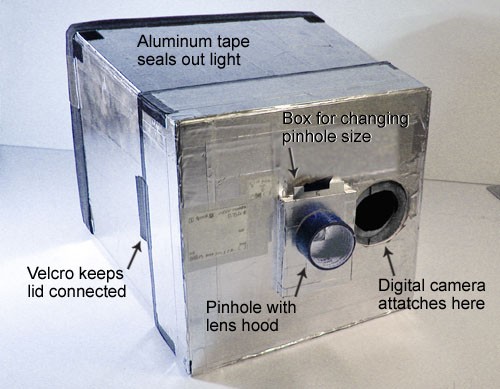 Figure 2. A lightbox-type digital pinhole camera (Hanft, 2005).
 -
Here are some tips on constructing a lightbox-type camera (for more details, see Hanft, 2005):
- The box depth is determined by how close your camera can focus. The further your projection screen is from the pinhole, the dimmer the light will be, and the longer exposures you'll have to take, so try to keep this reasonably short (10-12 inches, if possible).
- Paint the inside of the box flat black to prevent stray reflections. This is especially important with the long exposures you'll be using.
- Cover the outside of the box entirely with aluminum tape, to ensure that your box is light-tight.
- For the "window" for your digital camera, use a piece of rubber tubing from an old bicycle inner tube to make a tight-fitting rubber seal that will fit around the lens of your camera. This will perform two functions: 1) make a light-tight seal, and 2) hold the camera firmly in place.
- Also, remember that the camera needs to be tilted down slightly so that it does not block light entering the pinhole (see Figure 1 in the Introduction).
- Turning a digital SLR camera into a pinhole camera is much easier. All you need are some spare body caps, which you should be able to order from the camera store where you purchased the camera. Find the center of the body cap and drill a hole in it. Glue a pinhole made from thin aluminum, over this hole, and make the glue joint light-tight by covering it with black tape.
-
Here are some tips on making and measuring a pinhole (used for either type of camera:
- Here are instructions for making a pinhole from David Balihar: "A piece of metal cut from a drinks [soda] can, approximately 4 x 4 cm, is sufficient. First, using coarse sandpaper, remove the paint from the area where the hole should be, and try to make the metal as thin as possible. Then finish the surface by using fine sandpaper. Place the plate on a flat wooden block and, using a sharp needle, make the smallest hole possible. Be careful not to injure your hand and use a hard block to press down on the needle. Remove the embossed material from the reverse side of the plate using fine sandpaper. Place the needle into the hole again and, by gently pressing and turning the needle between your fingers, make the hole round. Smooth the hole again using sandpaper. It is necessary to repeat the process until the required diameter is achieved. A regular round hole in a very thin plate can be made with a bit of patience." (Balihar, 2006) Use the same size for each of the aluminum pieces, so that your pinholes are easily interchangeable on your camera.
- Remember to paint the back side of the pinhole metal flat black after you have made the pinhole. The back side will be inside the camera, and you want to prevent stray reflections inside the camera.
- There are many ways to measure the diameter of your pinholes. You can use a alide projector, overhead projector, or enlarger to project light through the pinhole, and measure the diameter of the enlarged image. To check the scale (enlargement factor) also measure the projected size of the edge of the aluminum. Another method is to use a flatbed scanner at 600 or 1200 dpi.
- Make a set of at least 3 different pinholes (more is even better) for your camera spanning a range of diameters from about 1.0 mm to 0.2 mm (or less).
- Experiment with exposure times so that you can photograph the same scene with each different pinhole to achieve about equal gray levels in the photographs. (The references in the Bibliography have information and calculators that should help with this. Knowing the diameters of your pinholes will also help.)
- If you are using a lightbox-type camera, it is best to keep the aperture setting constant, and change only the exposure time.
- Keep the camera steady by attaching it firmly to something heavy (e.g., a brick).
- The Bibliography has references that will show you how to quantify both resolution and sharpness for your photographs made with different-sized pinholes.
- Here are some questions you can attempt to answer with your pinhole camera.
- What pinhole diameter maximizes resolution for your camera?
- What pinhole diameter maximizes sharpness for your camera?
- How do these compare to the predicted results from the pinhole calculators in the Bibliography? If there are differences, can you explain them?
/-/https/www.sciencebuddies.org/cdn/Files/2420/5/Photo_img015.jpg)
Ask an Expert
Variations
- How does resolution with a pinhole compare to resolution with a normal camera lens?
- How does depth-of-field with a pinhole compare to depth-of-field with a normal camera lens?
- How does sharpness with a pinhole camera compare to sharpness with a normal camera lens?
- Examine exposure time in relation to pinhole size. Remember to keep digital camera aperture constant for lightbox-type camera. Use photo editing software and adjust exposure time to match gray values in the images taken with different-sized pinholes.
Careers
If you like this project, you might enjoy exploring these related careers:
/-/https/careerdiscovery.sciencebuddies.org/cdn/Files/1450/21/iStock-1227179796.jpg)
/-/https/careerdiscovery.sciencebuddies.org/cdn/Files/1457/17/pexels-photo-3861938.jpg)
/-/https/careerdiscovery.sciencebuddies.org/cdn/Files/1640/26/Fyysikot_tyossaan.jpg)
/-/https/careerdiscovery.sciencebuddies.org/cdn/Files/1692/17/unsplash-G1Xk2C87Rb8.jpg)
/-/https/careerdiscovery.sciencebuddies.org/cdn/Files/1429/17/unsplash-4pM4nhHyo9M.jpg)

/-/https/img.youtube.com/vi/JrV_f_omYHY/0.jpg)
/-/https/img.youtube.com/vi/MtiJz7gh1VU/0.jpg)
/-/https/img.youtube.com/vi/aAuN5ZnL4yE/0.jpg)