Abstract
Can you imagine designing and building a space telescope the size of a tennis court? Believe it or not, that is someone's job! Hundreds of engineers were involved in getting the James Webb Space Telescope (JWST) into space. This telescope has the potential to enable astronomers to see light from when the Universe was first formed. No one knows what amazing discoveries this might lead to, but already, JWST has delivered astounding deep space images that offer an unprecedented look at galaxies, star formation, exoplanets, and light that may be billions of years old. To make the telescope work properly, engineers had to overcome a number of challenges. In this science project, you can build your own model of key parts of the James Webb Space Telescope and discover firsthand how to solve a few of the engineering challenges.Summary
Brian Dodson, PhD, Science Buddies
Edited by Sandra Slutz, PhD, Science Buddies

Objective
To learn about multiple-mirror optics and conditions in space by building a light collector similar to that of the primary mirror of the James Webb Space Telescope. The light collector will be illuminated using a heat lamp, and the intensity of light reflected from the mirrors will be measured from behind a protective "sunshield."Introduction
Have you ever looked up at the night sky and wondered what was up there and how it all came to be? Have you thought about what kinds of planets are circling other stars and how stars are born? How big is space? How do we know? These questions also intrigue astronomers, who always want to know more about the history of the Universe. They wait eagerly for advancements in technology and engineering that may provide new answers.
The James Webb Space Telescope (JWST), or Webb Telescope for short, is a tool scientists believe has the potential to change how we view the history of the cosmos. JWST is a joint project between NASA, the European Space Agency, and the Canadian Space Agency. Launched into space on December 25, 2021, the Webb Telescope is the largest infrared telescope ever built. As explained in the video from Quanta Magazine, the Webb Telescope was built to study the formation of galaxies, planets outside of our Solar System (exoplanets), and newborn stars by examining their thermal (or infrared) radiation. By studying the atmospheres of exoplanets, the Webb Telescope will help us search the universe for other planets that could harbor life.
Why put a telescope into space? Because Earth's atmosphere gets in the way! Two main things happen to light from space as it passes through the atmosphere. First, the light bends, thus blurring the images of space objects when viewed by a telescope on the ground. You have probably seen what appear to be sheets of water when you travel along a highway. This mirage is caused by light being bent by layers of air having different densities (usually cooler air over the hot air directly above the pavement). In the same manner, Earth's atmosphere is full of air pockets with different temperatures, causing incoming light to dance around. This is why stars "twinkle." Second, although air looks transparent to our eyes, many types of light are blocked or absorbed in the atmosphere. In order to take advantage of all the types of light when examining a space object, a telescope has to be positioned in space.
The Webb Telescope isn't the first space telescope. The first such telescope was called Orbiting Astronomical Observatory 2 (OAO-2). It was launched in 1968 to examine the sky using ultraviolet light. Its scientific program was rich in results and resulted in five years of data. However, the best known of the space telescopes (and perhaps the most productive) has been the Hubble Space Telescope. Since its launch in 1990, Hubble has provided astronomers with more than a million astronomical observations, which have overturned many of our ideas about where the Universe came from and where it is going. Among other things, the Hubble Telescope measured the size of the Universe, provided the first evidence of "dark matter" and "dark energy," and observed the Universe to be expanding much faster than previously thought.
If the Hubble Telescope has been so successful, why do we want to build, launch, and operate the Webb Telescope? Well, you might be excited about buying an improved video game system that will play new games, or about hearing the latest collection of songs from your favorite artist. In the same way, astronomers are eager to use the Webb Telescope because it will let them study objects the Hubble Telescope could never even see!
One reason that the James Webb Space Telescope is able to provide images of objects that the Hubble Telescope cannot is that it has better light-gathering power. Light-gathering power is the ability of a telescope to collect light from an object in the sky—the more light, the better. The main, or primary, mirror of a reflecting telescope is the big mirror that collects light. The Hubble Telescope's primary mirror is 2.4 meters (m), or about 95 inches, in diameter. The Webb Telescope's primary mirror is almost three times larger in diameter (see Figure 1), and it collects a bit more than seven times as much light. The Webb Telescope is able to see about three times farther into the early Universe than the Hubble Telescope—far enough to see the very first light in the Universe!
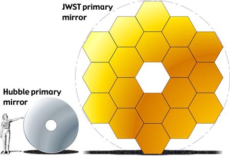
Figure 1.The James Webb Space Telescope's primary mirror will be almost three times the diameter of the Hubble Space Telescope's. (Graphic by: NASA)
Although a huge advantage for astronomers, the Webb Telescope's mirror was one of the engineering problems for constructing the telescope. The Webb Telescope's mirror is 6.5 m (more than 20 feet) in diameter, but the largest rocket that launched the telescope, the Ariane 5, can carry cargo of only about 3 m (roughly 15 feet) in diameter. So how was this huge mirror launched into orbit? To solve this problem, engineers took the Webb Telescope's 6.5-m primary mirror and divided it into 18 hexagonal segments. When the rocket reached its destination in space, the mirror segments (and the other parts of the telescope) had to automatically unfold from the rocket and use motors to properly align themselves. In the video from Northrup Grumman (one of the companies involved in designing and building the Webb Telescope), you can watch an animation of how the multiple-mirror assembly's unfolding and alignment was supposed to proceed.
The Webb Telescope is positioned too far from Earth (1.5 million kilometers) to send astronauts to fix alignment problems, so the engineers had to get things right on the first try. This alignment was no small challenge. To get the proper mirror shape for the telescope to work, the mirror segments needed to unfold within a few nanometers (nm) of what engineers had calculated as the best positions. (A human hair is about 50,000 nm in diameter, so 5 nm is very small indeed!)

The James Webb Space Telescope also faced another amazing engineering challenge—heat. Because the telescope will study the Universe using near- and mid-infrared light, the temperature of the telescope and its components must be controlled very carefully. It is designed to operate below 50 Kelvin (-370°F, or -223°C), with some parts even colder. While it may seem counterintuitive, keeping things cold in space can be a challenge. Objects on Earth can rely on convective cooling (heat is carried away by air or water) or conductive cooling (heat is carried away by direct contact with other solid objects). A spacecraft in a near vacuum does not have those options, and radiant heating from the Sun can cause spacecraft to get very hot. This problem was solved by using a sunshield (see Figure 2).
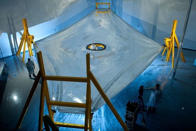 Image Credit: NASA / Public domain
Figure 2. This full-scale sunshield membrane (note the scientist standing in the middle) is being deployed on the membrane test fixture for the Webb Telescope at ManTech in Hunstville, AL, ready for an exact measurement of its three-dimensional shape. The sunshield has five of these layers, each of which must be precisely spaced with the next. (Photo by: Northrop Grumman Aerospace Systems)
During the building of the James Webb Space Telescope, astronomers calculated that the energy of the Sun's light hitting the sunshield would be approximately 250 kilowatts (kW). The sunshield had to reduce this energy to about 1 watt (W). To do this, engineers created a sunshield made up of five reflecting membranes, each of which is separated from its neighbor by about 15 centimeters (cm) of space. The membranes are formed of very thin layers of a plastic-like material called Kapton—about 25 microns (µ) thick, or about half the diameter of a human hair. Kapton is extremely strong and resistant to the thermal, radiation, and micrometeoroid-filled environment of space.
The working principle of the sunshield is rather simple, but as always, the devil is in the details. In Figure 3, sunlight hits the reflecting membranes of the sunshield from the left. The first membrane reflects most of the incident light from the Sun but absorbs and reradiates part of that energy. Most of the energy that is reradiated into the space between the first and second membrane eventually bounces out the sides into space. This reduction of energy takes place between each pair of membranes, until a tiny remainder of the Sun's energy is finally absorbed by the Webb telescope and instruments. At 12-by-22 m (about the size of a tennis court), the sunshield is so large that it also had to be folded to fit into the rocket and unfolded and positioned upon arrival (as shown in the video above).
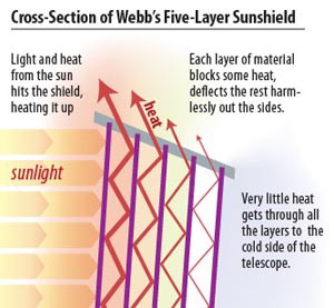 Image Credit: NASA / Public domain
Figure 3. The Webb Telescope has a sunshield made up of five layers. Each layer blocks and deflects heat until the final heat reaching the telescope's instruments contains only about 4 parts in a million of the initial energy. (Graphic by: NASA)
Although we can't send a telescope into orbit for a science project, some aspects of the James Webb Space Telescope's unique features can be experimented with on Earth—and even in your home! The goal of this project is to construct a multiple-mirror light collector similar to the Webb Telescope's primary mirror made up of 18 smaller mirrors. This multiple-mirror assembly is then illuminated using a heat lamp instead of a far-off celestial object. We then develop a "sunshield" for a kitchen thermometer, to protect it from the direct heat of the heat lamp. Having done that, we will learn a good deal about multiple-mirror optics by measuring the intensity of the light reflected from the mirrors as the position of the thermometer is changed. This project illustrates the principles and practice of a multiple-mirror telescope and a cooling sunshield—two engineering features essential to the successful operation of the Webb Telescope.
Terms and Concepts
- James Webb Space Telescope
- Infrared telescope
- Exoplanet
- Atmosphere
- Hubble Space Telescope
- Light-gathering power
- Primary mirror
- Multiple-mirror assembly
- Sunshield
- Infrared astronomy
Questions
- Why was the Webb Telescope designed to observe the Universe using infrared light?
- What special features of the Universe do astronomers hope to view with the Webb Telescope?
- Why was the James Webb Space Telescope not placed in an orbit around the Earth?
Bibliography
The official NASA Website for the James Webb Space Telescope is at this link:
- National Aeronautics and Space Administration. (n.d.). James Webb Space Telescope. Retrieved December 29, 2021.
Here is another website for the JWST:
- Space Telescope Science Institute. (n.d.). NASA's James Webb Space Telescope. Retrieved December 29, 2021.
Materials and Equipment
Most of the items on this list can be obtained at a hardware store (HS) or at a craft shop (CS).
- Box cutter or X-ACTOTM knife (1, CS)
- 20-by-30-by-1/2-inch foamboard (1, CS)
- 20-by-30-by-1/4-inch foamboard (1, CS)
- 18- to 24-inch straight ruler (1, HS or CS)
- 2-inch-long lamp nipple with 3/8-inch outside diameter (1, HS)
- Lamp couplings to thread over the lamp nipple (about 1/2-inch long) (2, HS)
- 3/8-inch nylon washers (2, HS)
- 3/16-inch rubber O-rings (2, HS)
- OXO Good Grips® digital leave-in meat thermometer, model #1158800. Other thermometers can be used, but this one can be obtained at Amazon.com
- 250-watt heat lamp (1, HS)
- Portable work light for heat lamp (1, HS)
- Heavy-duty aluminum foil
- 2-inch diameter round mirrors (7, CS). Also available at online vendors such as Amazon.com
- 2- to 3-inch wood screws (12, HS)
- Hot-melt glue gun and glue sticks (HS or CS)
- Small Velcro® dots (CS or HS)
- Small pushpins (CS)
- Small rubber bands (CS)
- Utility table (1). Must be sturdy, larger than 15-by-40 inches, have a lip you can clip a light to, and placed in an area where you can keep your experiment set up for a couple of days.
- Black paint or a dark food sauce, like Worcestershire sauce.
Disclaimer: Science Buddies participates in affiliate programs with Home Science Tools, Amazon.com, Carolina Biological, and Jameco Electronics. Proceeds from the affiliate programs help support Science Buddies, a 501(c)(3) public charity, and keep our resources free for everyone. Our top priority is student learning. If you have any comments (positive or negative) related to purchases you've made for science projects from recommendations on our site, please let us know. Write to us at scibuddy@sciencebuddies.org.
Experimental Procedure
The procedure for this project may look complicated—but it is not. The steps below are very detailed, and lots of diagrams and photos show you how to put it together. Remember, you can always keep tinkering with your multiple-mirror model until it is perfect, but the JWST engineers and builders only had one chance to get the JWST's setup right!
Assembling the Optical Bench
- Cut a piece of 20-by-30-by-1/2-inch foamboard down the middle of the short sides to give two pieces, each measuring 10 by 30 inches. To cut the foamboard, trace a line and cut into it with a box cutter or X-ACTO™ knife, then bend the board so it breaks along the cut. Put one of the pieces aside for later use.
- Attach the straight ruler to the top surface of the foamboard so that it lies along one edge, and the 0-inch end is 6 inches from one of the short sides (see Figure 4 below). It is best to tape or glue the ruler at its ends so the thermometer mount can slide along the edge of the ruler. This helps measure the position of the thermometer during the experiments.
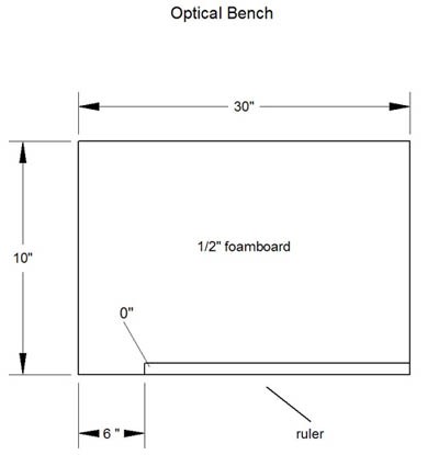 Image Credit: Brian Dodson, Science Buddies / Science Buddies
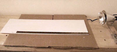 Image Credit: Brian Dodson, Science Buddies / Science Buddies
Figure 4. The diagram (top) and photo (bottom) show what the base for the optical bench will look like. Note the dimensions, in inches, marked on the diagram.
- Next, make the sliding thermometer mount. Start by cutting a 10-by-10-inch section from the 20-by-30-by-1/4-inch foamboard.
- Cut the section along the dotted lines into four pieces as shown in Figure 5 below. The ends of the slot in the middle piece need not be rounded. Assemble the pieces of the thermometer mount to look like the photo in Figure 6. Use hot glue between the foam pieces and form thin bands of glue along the edges so that the thermometer mount is strong enough to last through the experiments.
 Image Credit: Brian Dodson, Science Buddies / Science Buddies
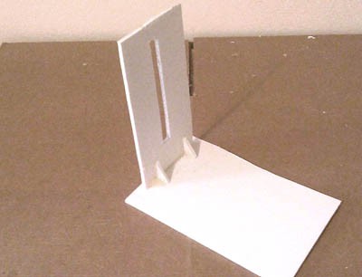 Image Credit: Brian Dodson, Science Buddies / Science Buddies
Figure 5. The diagram on the top shows the pattern for cutting out the pieces to create the thermometer mount. Cut along the dotted lines, making sure to use the same measurements, in inches, listed in the diagram. A photo of the assembled thermometer mount is shown on the bottom.
- Next, build the thermometer holder. Note: The parts for the thermometer holder are chosen to fit an OXO Good Grips® digital leave-in meat thermometer. This thermometer reads temperature with a resolution of 0.1 degrees C, and is well suited for this experiment. Other kitchen thermometers may be used, although mechanical (dial-type) thermometers make the experiment rather difficult because of lack of resolution and long response time. Also, you may have to design a different thermometer holder.
- Collect together the thermometer, the lamp nipple, the two lamp couplings, the two 3/8-inch nylon washers, and the two 3/16-inch rubber O-rings. All the parts are shown in Figure 6 below.
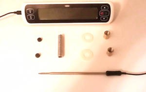 Image Credit: Brian Dodson, Science Buddies / Science Buddies
 Image Credit: Brian Dodson, Science Buddies / Science Buddies
Figure 6. The photo (left) and diagram (right) above show the parts needed to build the thermometer holder.
- Using Figure 7 below as a guide, place the two nylon washers onto the lamp nipple. Then thread the lamp couplings onto the lamp nipple so that the glue used later won't fill the threads on the lamp nipple, or if it does, unthreading the lamp couplings will form the nipple threads anew. Next, insert the two O-rings in the ends of the lamp nipple. Insert the thermometer probe into the O-rings to make sure that it fits. Then glue the O-rings into the lamp nipple, being careful not to spread glue over the threads of the lamp nipple. You can use hot glue or superglue for this.
 Image Credit: Brian Dodson, Science Buddies / Science Buddies
 Image Credit: Brian Dodson, Science Buddies / Science Buddies
Figure 7. The diagram on the top shows what the completed thermometer holder should look like from the outside. The drawing on the bottom shows a cross-section through the thermometer holder.
- After allowing the glue to completely harden, remove the lamp couplings and the nylon washers. Place the lamp nipple through the vertical slot on the thermometer mount. Then on each side of the thermometer mount place a nylon washer followed by a lamp coupling. Thread the lamp couplings onto the lamp nipple until the thermometer holder is held firmly in place. Be sure that it is not so tightly held that it is hard to slide the holder up and down. Movement in this slot is the way we will change the height of the thermometer.
- Slide the OXO thermometer probe through the thermometer holder. The sensitive area of the thermometer probe (the pointy end) winds up on the side of the slot with the triangular foamboard braces. The completed thermometer probe in its holder and mount are shown below in Figure 8.
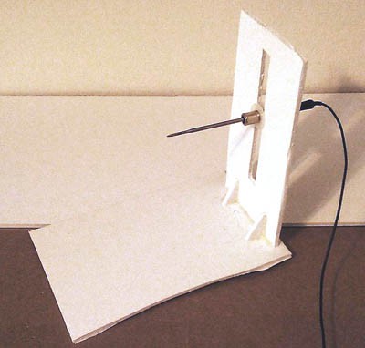 Image Credit: Brian Dodson, Science Buddies / Science Buddies
Figure 8. The completed thermometer holder and mount should look like the one in this photo.
- Now that the pieces are all built, you are ready to set up the optical bench.
- Start with a sturdy table on which you can leave your equipment set up for some time. It is a good idea to cover the table with cardboard for protection. Place the optical bench on the table so that the ruler is toward you and the 0-inch end of the ruler is to your left. The heat lamp should be mounted on the table at the right end of the optical bench so that the bulb faces to the left, and so that the center of the bulb is about 4 inches above the surface of the optical bench. (Note: The orientation of the optical bench and heat lamp can be reversed if more convenient. We will continue the instructions for the orientation used above.)
- Place the thermometer mount on the optical bench so that the thermometer probe is positioned in front of the heat lamp, and the vertical edge of the mount slides along the ruler of the optical bench. The completed setup is shown below in Figure 9.
 Image Credit: Brian Dodson, Science Buddies / Science Buddies
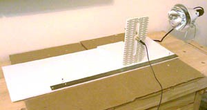 Image Credit: Brian Dodson, Science Buddies / Science Buddies
Figure 9. The diagram (top) and photo (bottom) show what the optical bench should look like after the setup is complete.
Creating the Multiple-Mirror Assembly
Now that we have built the optical bench on which our measurements will be taken, it is time to design and construct the multiple-mirror assembly, or MMA.
- Cut a hexagon from the leftover piece of the ½-inch-thick foamboard. The hexagon should measure 4 inches on a side. Mark the placement of the mirrors as shown below in Figure 10.
 Image Credit: Brian Dodson, Science Buddies / Science Buddies
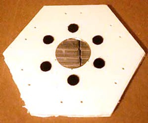 Image Credit: Brian Dodson, Science Buddies / Science Buddies
Figure 10. The diagram (left) shows the placement of the small Velcro® mounting patches (grey circles) and the adjustment screws (black spots) for the small mirrors on the foamboard hexagon. The mirrors are not shown on the diagram, but the mounting locations for the small mirrors is indicated by the dotted circles. The adjustment screws are probably best made of 2- to 3-inch-long wood screws, which can be driven right through the foamboard, and have sufficiently coarse threading to hold in the foam. The idea is to mount the small mirrors onto the mirror mount with the small Velcro® patches, and then adjust the tilt of the mirrors by changing the length of the adjusting screws that penetrate the foamboard. As shown in the photograph (right), the small center mirror is firmly glued to the foam board and has no adjustment screws.
- Glue the center mirror to the foamboard hexagon. Arrange and attach the Velcro® patches for the surrounding mirrors as shown above in Figure 10. Poke holes where the attachment screws belong.
- For each of the remaining six mirrors, attach the other side of the Velcro® patch to the bottom backside. Use the glue gun to glue a pushpin to the top backside (opposite the Velcro® patch) of the mirror as shown in Figure 12 below.
 Image Credit: Brian Dodson, Science Buddies / Science Buddies
 Image Credit
Figure 11. From the back, each of the six surrounding mirrors look like the diagram (left) and photo (right) above. A Velcro® patch (grey circle in diagram) is attached opposite to a pushpin.
- Using the Velcro® patches, attach the six remaining mirrors to the mirror mount. Put in the adjustment screws. As shown in Figures 13 and 14 below, tie each mirror's pushpin rod to the hexagon mirror mount with a small rubber band so that the mirrors will be held firmly against the adjustment screws. Do not stretch the elastic bands so tight that they pull the pushpin out of the glue holding it.
 Image Credit: Brian Dodson, Science Buddies / Science Buddies
Figure 12. This diagram shows a side view of one of the six surrounding mirrors attached to the hexagonal mirror mount.
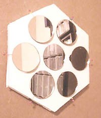 Image Credit: Brian Dodson, Science Buddies / Science Buddies
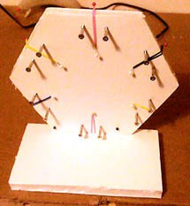 Image Credit: Brian Dodson, Science Buddies / Science Buddies
Figure 13. These photos show the completed MMA from the front (left) and back (right). Notice that in this setup, additional pushpins were used to anchor the rubber bands to the back of the assembly.
- Mount one side of the hexagonal MMA on a base of the remaining 1/2-inch foamboard, as in Figure 14 above. Then mount this base, as shown in Figure 14 below, on the optical bench.
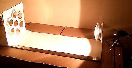 Image Credit: Brian Dodson, Science Buddies / Science Buddies
Figure 14. When completed, the mirror-mount assembly should be attached to the optical bench you created. Note: The shape of the mirror-mount assembly in this photo differs slightly from the instructions above, but the placement of the mirrors and the function is identical.
Creating a Thermometer Sunshield
The main measurements taken in this experiment involve measuring the increase in temperature caused by the light of the heat lamp reflected from the multiple mirrors. However, the thermometer probe will often be closer to the heat lamp than to the multiple mirrors. This means that the thermometer probe must be well shielded from the direct light of the heat lamp. The JWST faces a similar problem, as it has to observe extremely faint infrared objects while located in the direct heat of the Sun. In both cases, the solution is a lightweight but effective sunshield. The sunshield for this multiple-mirror experiment needs to protect the thermometer from as much of the heat lamp's direct heat as possible without blocking the mirror assembly.
- Following the dimensions in Figure 16 below, cut out the pieces of foamboard to make the sunshield.
- The 1/2-inch foamboard with the rectangular opening (top left of Figure 15) is called the front plate and enables the probe to detect light reflected from the multiple mirrors. The other two 1/2-inch foamboard pieces are spacer blocks.
- The 1/4-inch-thick piece (top right of Figure 15) is called the back plate and is positioned nearest to the heat lamp. This foamboard is in the form of a rectangle with a central cutout. The shape of the central cutout is not critical, but it must be at least as large as the opening in the 1/2-inch foamboard. The bottom of the cutout will be sealed by aluminum foil.
 Image Credit: Brian Dodson, Science Buddies / Science Buddies
Figure 15. This diagram shows the dimensions and assembly of the sunshield pieces.
- Using the diagram above in Figure 15 and the photos below in Figure 16, assemble the sunshield.
- Glue aluminum foil to the front and back surfaces of the back plate so that the shiny side of the foil is on the outer surface of the back plate. This piece provides protection from radiant heat by first reflecting away the heat from the heat lamp, providing an air space that is only heated by emission of heat from the dull side of the first layer of foil, reflecting the heat that penetrates into the air space away from the remainder of the shield. Finally, the shiny surface does not effectively radiate heat absorbed by the front surface foil into the region of the spacer blocks.
- Glue the spacing blocks to one side of the aluminum foil covering the back plate. Position the blocks at the edges of the back plate so that the foil-covered hole in the back plate is not covered by the blocks.
- Glue another layer of aluminum foil on top of the spacing blocks so that a foil bridge is formed between them, with the shiny side of the foil facing the back plate. The sides of the spacing blocks remain open; the shielding effect results from the reflection of the heat penetrating into this region from between the spacer blocks. This is very similar to how the JWST sunshield will provide the main cooling for that telescope—by reflecting the heat into empty space.
- Glue the front plate on top of the spacing blocks.
- Make a central hole in the front spacing block into which the thermometer probe can be inserted. Most thermometer probes are sharp enough to pierce the foam block, but probes with a large, blunt tip would best be inserted through a hole previously made in the foam block. The tip of the thermometer probe should not touch any part of the sunshield, so that the warm foam does not heat the thermometer. When completely assembled, the multiple-mirror assembly and optical bench should look like Fig. 17 below.
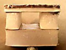 Image Credit
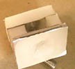 Image Credit
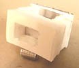 Image Credit
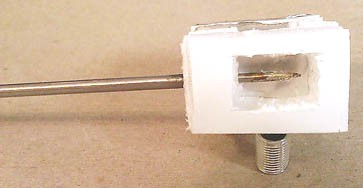 Image Credit: Brian Dodson, Science Buddies / Science Buddies
Figure 16. All sides of the sunshield can be seen in the photo series above.
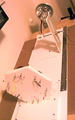 Image Credit: Brian Dodson, Science Buddies / Science Buddies
Figure 17. When the completed multiple-mirror assembly light collector is set up, it should look similar to the photo above.
Testing the In-Progress Model
- First do a basic function test to confirm that the thermometer probe responds properly to the heat lamp. You should see that the thermometer's temperature reading increases when the heat lamp is on.
- With the heat lamp off, use the optical bench's ruler to position the thermometer probe holder 4 inches in front of the center of the heat lamp. In your lab notebook, record the temperature shown by the thermometer—this is room temperature. Now turn on the heat lamp, and allow the thermometer probe to heat up. You will have to wait about five minutes for the temperature to stop rising. Record this temperature in your lab notebook, and turn off the heat lamp.
- Calculate the change in temperature, and write this down in your lab notebook. The change is the important piece of data that you want to collect. For example, if the initial room temperature is 26.7 degrees C and the thermometer probe reads 105.0 degrees C after, the rise in temperature of the probe caused by the heat lamp was 105.0 − 26.7 = 78.3 degrees C. This is the actual data point from this measurement. We will be measuring differences in temperature of a few degrees, and if we don't keep track of room temperature, important data will be miscalculated.
Safety Notes:
- Do not look directly into the heat lamp. If necessary, hang a towel between yourself and the heat lamp (but far enough from the lamp so the towel doesn't burn) to shield your eyes.
- Use caution around an active heat lamp—adult supervision is strongly recommended. Remember, the heat lamp can heat objects to over 100 degrees C (the temperature at which water boils)!
- Keep all parts of the experimental apparatus at least 4 inches from the heat lamp, as it can melt the hot glue.
- The effects you are interested in exploring with this apparatus may only result in a temperature change of a couple of degrees. In order to make the changes as large as possible and maximize the ability to detect the effects, try coating the thermometer probe in a dark color. Dark colors absorb more light, and thus heat, than light colors.
- First, use the ruler to place the thermometer probe 6 inches away from the heat lamp. With the heat lamp off, read and record in your lab notebook the temperature. This is the room temperature, TR1.
- Turn the heat lamp on, wait five minutes or more until the temperature is stabilized, then read and record the new temperature as TH1.
- The temperature rise measured with the uncoated probe is thus ΔT1 = TH1 - TR1. Calculate and record ΔT1 in your lab notebook.
- Coat the thermometer probe with black paint or if you would still like to be able to use the thermometer for cooking after your experiments are done, use a dark sauce like Worcestershire sauce. If using a sauce, simply dip the probe in the sauce and hold the probe approximately 6 inches from the heat lamp to dry it. Repeat the coating process at least twice.
- Repeat steps a through c with the coated thermometer probe. Always remember to retake the room temperature reading (this time call it TR2 ) in case the temperature has changed while you were doing other things. Calculate the coated temperature rise (ΔT2 = TH2 − TR2) and record it in your lab notebook.
- If ΔT2 is greater than ΔT1 then the coating increases the heat absorption efficiency of the probe. What does your data tell you? If you observe an efficiency increase, calculate the percent increase in efficiency using Equation 1 below.
Equation 1.
- Having built the sunshield, we want to test the design to see how well it works. Ideally, when the sunshield is in place, the thermometer probe will only respond to the heat of the light reflected onto it by the multiple-mirror assembly, but not to the direct light of the heat lamp hitting the rear of the sunshield. The amount of shielding (also called thermal isolation) provided by the sunscreen can be determined using temperature measurements.
- Position the thermometer mount so that the thermometer probe is positioned at the 16-inch mark on the ruler. Now, measure the probe temperature with no sunshield in place and the heat lamp off, then after the heat lamp has been turned on for about five minutes. By this time, the temperature reading should have reached a steady value. Calculate the temperature rise exactly as you did in testing the probe coating. Call the unshielded temperature rise ΔTU.
- Now allow the apparatus to cool, and then mount the sunshield on the probe. Measure the temperature with the heat lamp off, and again with the heat lamp on after the temperature has equilibrated. Call the shielded temperature rise ΔTS.
- If ΔTS is smaller than ΔTU, the sunscreen is effective. Use Equation 2 below to determine how effective. Note: You will not be able to build a 100 percent effective shield—even NASA has not done that. Even 25 percent effectiveness would be a very good sunshield.
Equation 2.
- The direct heating of the thermometer probe by the heat lamp changes as the position of the probe relative to the heat lamp changes. To see this, and to determine how effective the sunshield is at various probe positions, make a series of measurements.
- Starting at 16 inches, set the thermometer holder at a position every 2 inches from 0 to 16 inches according to the ruler, and then measure the temperature with and without the sunshield in place. Make sure to check the room temperature regularly to compensate for any changes. Record the measurements in a data table, like Table 1 below, in your lab notebook. You have already done the first measurement, at the 16-inch position, in step 3 above.
- Make a graph, like the one in Figure 18 below, to illustrate the effectiveness of the sunshield at different positions. Where is the sunshield most effective? How does distance from the heat lamp change the lamp's ability to heat the thermometer probe?
| Probe Position | Room Temperature in °C (TR) | Temperature Without Sunshield in °C (TU) | Temperature with Sunshield in in °C (TS) | ΔTS with Sunshield in °C | ΔTU Without Sunshield in °C | % Reduction by Sunshield |
| 16 inches | ||||||
| 14 inches | ||||||
| 12 inches |
To visualize this data, it is useful to make a plot of temperature increase versus probe position for the probe with and without the sunshield:
 Image Credit: Brian Dodson, Science Buddies / Science Buddies
Example graph for a shielded and unshielded thermometer probe shows temperature over probe position. Temperature for the probe increases as the probe position increases, but the overall temperature for a shielded probe is much lower than the temperature for an unshielded probe.
Figure 18. Create a graph, like this one, with temperature increase in degrees C on the y-axis and probe position in inches on the x-axis for both the shielded and unshielded data. Do not copy this graph; the data is fictional. Data from a real setup will be different.
Aligning the Multiple-Mirror Assembly
In the James Webb Space Telescope, the 18 hexagonal mirror segments must be aligned so that their images form a single wavefront—that is, so they produce a single image at the focal plane that is 18 times brighter than that of a single mirror and has five times the spatial resolution. For our experiments, the seven mirrors on the MMA have to be aligned in a similar manner. Our mirrors are flat, however. This makes the alignment process a great deal easier, as the goal is not that they reflect the light from the heat lamp to a single focus, but rather that the light reflected from the seven mirrors add together to illuminate a single on-axis spot. If each mirror is 2 inches in diameter, the focal spot will also be 2 inches in diameter. Figure 19 below shows how the alignment procedure takes place, and how the alignment tool works.
 Image Credit: Brian Dodson, Science Buddies / Science Buddies
Figure 19. This diagram shows how the alignment tool works. In brief, the heat lamp (light source) emits a beam of intense light. The alignment tool stands on the optical bench at the point where we want the mirrors to reflect onto a single central spot (in our experiments, we would expect this to be the location where the temperature is highest). For convenience, we call this point the focal length of the MMA, although this usually refers to the position at which an image is formed. In use, the opening in the alignment tool is placed at the desired focal length in line sequentially with each one of the six small mirrors on the edge of the MMA. After checking to see that the chosen small mirror is being hit by the light from the heat lamp, the adjusting screws are used to change the tilt of the small mirror until the reflected light is centered on the alignment tool. This is done for each of the six edge mirrors in turn, and the result should be an MMA having the desired focal length.
- To construct the aligment tool, cut a hexagon the same size as the multiple-mirror mount from a leftover piece of the 1/4-inch foamboard. Draw two 2-inch diameter circles (the same size as the mirrors) on the hexagon as shown in Figure 21 below. One circle should be in the center of the hexagon, identical to the center mirror of the MMA, and the second circle should be centered on one edge of the hexagon, identical in placement to one of the surrounding mirrors of the MMA.
- Carefully cut out the circle on the edge of the hexagon. The alignment tool should look similar to the photo in Figure 20 below.
 Image Credit: Brian Dodson, Science Buddies / Science Buddies
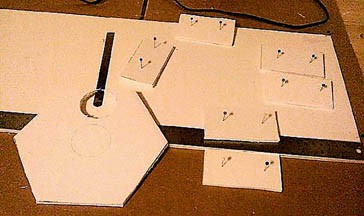 Image Credit: Brian Dodson, Science Buddies / Science Buddies
Figure 20. The diagram (top) is a sketch of the completed alignment tool. Note that the circle on the edge, pictured in the photo on the bottom, is cut out to permit light from the heat lamp to pass through.
- Cut out six 3-by-2-inch rectangles from the leftover 1/2-inch foamboard. These will be the "feet" of the alignment tool so that it can stand up without being held. Glue one foot onto each side of the hexagon. You may need to use pushpins to hold the feet in proper alignment until the glue has dried.
- Next, try aligning the mirrors with the alignment tool. If the alignment tool works, the temperature rise (ΔT) driven by the light from all seven aligned mirrors should be much greater (ideally seven times greater) than the temperature rise from just a single mirror.
- Place the thermometer probe at the 6-inch mark. The sunshield should be in place, and the multiple-mirror mount should be at the far end of the optical bench (opposite the heat lamp). Place the alignment tool at about the 9- to 10-inch mark so that it shades all but one of the edge mirrors from the heat lamp. Measure the temperature with the heat lamp off (this is the room temperature), and again with the heat lamp on after the temperature has equilibrated. Calculate the temperature rise (ΔT) from the single mirror.
- Turn off the heat lamp and allow everything to cool. Move the thermometer probe out of the way and place the alignment tool at the 6-inch mark; this will be the focal length for which we are trying to set the MMA. Start by aligning the topmost mirror in the MMA. To do this, line up the opening in the alignment tool with the topmost mirror. Turn on the heat lamp. Make sure the topmost mirror is being illuminated by the heat lamp. Use the adjustment screws in the back of the MMA to change the tilt of the topmost mirror until the reflected light is focused on the center circle of the alignment tool. Rotate the alignment tool clockwise and repeat the procedure with each mirror until all six surrounding mirrors have been aligned.
- Now that the mirrors have been aligned for a focal length of 6 inches, repeat step 4a after removing the alignment tool to calculate the temperature rise (ΔT) from all seven mirrors. Does the properly aligned MMA result in a larger or smaller temperature rise? Calculate the increase or decrease in efficiency by adapting Equation 1 above.
Technical Note:
In an ideal world, we would expect that the temperature rise from all seven mirrors would be sevenfold (seven times) greater than the temperature rise from just one mirror, but you probably didn't get a sevenfold increase. We definitely didn't when we tried the experiment! What happened?
Well, first, the sunshield covers much of the center mirror, so most of the light hitting the center mirror is lost, and we should really expect a sixfold increase in intensity. However, there are also minor flaws in the assumptions underlying the alignment procedure.
Take another look at Figure 20 above. The first questionable assumption made here is that the light from the light source (heat lamp) forms a parallel beam. However, this is not how light is emitted from a heat lamp—as shown in Figure 21 below, the light is mostly emitted in a forward direction, but fills a cone with light rays at all angles that begin at the front surface of the heat lamp and fit within the cone.
 Image Credit: Brian Dodson, Science Buddies / Science Buddies
Figure 21. This diagram shows what happens when a real heat lamp is used. The heat lamp is smaller in diameter than the MMA, and most of its light is emitted directly by the filament—the light that reflects off the sides of the heat lamp is considerably less intense. These factors cause misalignment.
Notice on the figure that a portion of the bright central spot misses the small mirror it is intended to strike. By itself this is not so terrible an error, as all the small mirrors will be illuminated directly by the filament when the alignment tool is removed.
However, the incident light from the filament does not strike the small mirrors parallel to the optical axis, but from a somewhat different angle than does the light we are using for alignment. This means that the reflections of the brightest illumination on the mirrors will not be reflected onto a single central spot, but each will miss that spot to some extent. In addition, the light from the heat lamp is diverging. Thus, as the probe is moved farther away from the MMA, the lit spot from each of the small mirrors expands, and their combined intensity decreases.
We see that the alignment procedure outlined above is less than perfect. Our experiment can still be carried out using the above alignment procedure, as it is reproducible, and the results will tell us something about how large the alignment errors may be. However, you may be able to design a better alignment procedure. We suggest that the measure of a good alignment procedure is the size of the temperature rise on the central axis measured at the focal length. The larger this increase is, the better the alignment is likely to be.
Testing the Completed Model: On-Axis Performance Testing
Now that you have completed assembling, aligning, and making sure the model works, it is time to get down to the real performance testing.
- The first test you will make is to measure the on-axis temperature rise as a function of ruler distance on the optical axis of the MMA. It will help to define a 3D system of coordinate axes as shown below in Figure 22. We will call distance along the ruler X, with Z pointing right up at the ceiling, and the horizontal distance between the pointy end of the thermometer probe and the ruler called Y.
 Image Credit: Brian Dodson, Science Buddies / Science Buddies
Figure 22. The diagram shows the 3D coordinate system used for on-axis testing.
- Begin by positioning the pointy end of the thermometer probe on the MMA optical axis by adjusting the Y and Z position of the probe. The object now is to measure the temperature rise of the probe as a function of X. Meaning you'll keep the Y and Z position constant and only change the X position. Among other goals, we intend to identify the X position at which the temperature rise is greatest.
- In aligning the multiple-mirror assembly steps above, the MMA was aligned to a desired focal length of 6 inches. Using this same 6-inch focal length alignment, you will measure the on-axis temperature rise every half inch on the ruler from 3 to 9 inches.
- Start with the thermometer probe at the 3-inch ruler position. Take a room temperature measurement (thermometer probe reading with the heat lamp off), then switch on the heat lamp, wait for the temperature to stabilize (approximately five minutes) and record the thermometer probe temperature. Write down all your measurements in a table, like Table 2 below, in your lab notebook. Move the thermometer probe up half an inch on the optical bench ruler and repeat. Keep doing this, stopping every third measurement or so to check the room temperature. The last measurement should be at the 9-inch mark on the optical bench.
- Note that the size of the relative temperature changes from moving the thermometer probe half an inch along the optical axis are going to be small. This means that the measurement time does not have to be as long as before. This is also rapid enough that you can take room-temperature measurements after every three moves of the thermometer probe, rather than after every movement.
- Make sure the heat lamp has been switched off for at least ten minutes before taking a room temperature reading.
- Use your judgment and your knowledge of the conditions of the room in which you are working. If the temperature is changing quickly, take more room temperature readings. How many you took and for what reason should be a part of your report. Tip: Try to set up your work table away from any open windows, fans, heating vents, or other places where the air might be moving rapidly and changing temperature.
- Start with the thermometer probe at the 3-inch ruler position. Take a room temperature measurement (thermometer probe reading with the heat lamp off), then switch on the heat lamp, wait for the temperature to stabilize (approximately five minutes) and record the thermometer probe temperature. Write down all your measurements in a table, like Table 2 below, in your lab notebook. Move the thermometer probe up half an inch on the optical bench ruler and repeat. Keep doing this, stopping every third measurement or so to check the room temperature. The last measurement should be at the 9-inch mark on the optical bench.
| Probe Position | Measured Temperature | ΔT as Measured |
| Room Temp | ----- | |
| 3 inches | ||
| 3.5 inches | ||
| 4 inches | ||
| Room Temp | ----- |
- Make a line graph of your data with the temperature rise (ΔT) on the y-axis and the thermometer probe position (in inches) on the x-axis. According to the graph, where is the greatest temperature rise? How does this relate to the focal length of the MMA? Is it what you expected or not? If it isn't what you expected, read the technical note above and see how you can apply the information there to understand what happened.
Testing the Completed Model: Focal Plane Temperature Variations
The intensity of the light will change at a fixed distance from the MMA as the thermometer probe is moved around the focal plane (Z and Y positions). You will measure this in the same manner you measured the on-axis (X position) dependence.
- From the on-axis performance testing, you experimentally determined the X position with the highest temperature change. Place the thermometer probe at this X position for all of your focal plane temperature testing.
- First, determine how the thermometer probe's Z position affects temperature rise.
- Start with the thermometer probe at the lowest possible position in the thermometer holder. Measure the temperature change (ΔT) as you did in the on-axis testing above. Remember to take consistently spaced room temperature measurements as needed.
- Continue increasing the Z position by half-inch increments and taking measurements, until the thermometer probe is at the highest possible position in the thermometer holder. Make a table in your lab notebook, similar to Table 2, to record your measurements.
- Make a line graph of your data with the temperature rise (ΔT) on the y-axis and the thermometer probe's Z position (in inches) on the x-axis. According to the graph, what is the Z position with the greatest temperature rise?
- Next, determine how the thermometer probe's y-axis position affects temperature rise. Make sure the thermometer probe is placed at the optimal Z position you determined above in step 2.
- Lay a ruler perpendicular to the ruler glued onto the optical bench. You will use this second ruler to determine the Y position in inches.
- By eye, make a rough estimate of where the cone of light is from the heat lamp. Start with the thermometer probe at the lowest Y-position setting that still seems to be within the cone of light. Measure the temperature change (ΔT) as you did in the on-axis testing above. Remember to take consistently spaced room temperature measurements as needed.
- Continue increasing the Y-position by half-inch increments and taking measurements, until the thermometer probe at what you estimate to be the far side of the heat lamp's cone of light. Make a table in your lab notebook, similar to Table 2, to record your measurements.
- Make a line graph of your data with the temperature rise (ΔT) on the y-axis and the thermometer probe's Y position (in inches) on the x-axis. According to the graph, what is the Y position with the greatest temperature rise? Look back at all your data. Is this the greatest temperature rise you've recorded? Why or why not?
Ask an Expert
Global Connections
The United Nations Sustainable Development Goals (UNSDGs) are a blueprint to achieve a better and more sustainable future for all.

Variations
For the variations below you may find it helpful to read about and follow the Engineering Design Process.
- Try different probe coatings. Which probe coating(s) maximize the detection ability of the apparatus?
- Design various solar shields and see which ones do the best job of shielding the probe. You can even try a design exactly like the JWST's! Hint: Remember to make sure your sunshield is not interfering with your ability to detect heat from the MMA.
- Figure out a better alignment method. For example, it might be possible to improve the alignment by removing the heat lamp and using a laser pointer mounted in the thermometer holder to provide the light. Safety Note: Be careful not to look into the laser pointer beam. Younger children should have parental supervision for this. The sliding thermometer holder would be placed sideways on the optical bench so that the laser pointer is emitting its laser light to the left as in Figure 23 below:
 Image Credit: Brian Dodson, Science Buddies / Science Buddies
Figure 23. This diagram shows one way to set up a laser to align the MMA. With a little thought and experimenting, you may design an even better alignment method!
The beam from the laser pointer can now be pointed at the center of one of the small mirrors by sliding the thermometer sliding mount in and out along the straightedge, and sliding the laser pointer up and down in the slot of the thermometer sliding mount.
Once this is accomplished, place the alignment tool along the ruler at the desired focal length, oriented so that the beam goes through the aperture in the tool. Then adjust the small mirror using the adjustment screws so that the incident laser beam reflects directly onto the pre-measured central point of the alignment tool. The result should be an MMA that is more precisely aligned to the desired focal length.
To see if this hypothesis actually works, try aligning your MMA both ways, and carry out the on-axis heating and focal plane testing.
Careers
If you like this project, you might enjoy exploring these related careers:


Related Links
- Science Fair Project Guide
- Other Ideas Like This
- Physics Project Ideas
- Astronomy Project Ideas
- Space Exploration Project Ideas
- My Favorites