Abstract
Sometimes engineers get ideas to build robots from animals in nature. There are robot dogs, robot snakes, robot birds, robot cheetahs, and even tiny robotic insects! In this science project, you will build a robot insect of your own. The robot will automatically drive toward a light source, mimicking a behavior called phototaxis, seen in some insects. You will build your own robot and then make adjustments so it can reliably drive toward a light.
Summary
none
A kit is available from our partner Home Science Tools®. See the Materials section for details.
No issues
Ben Finio, PhD, Science Buddies
/-/https/i.ytimg.com/vi/avESoUJhREA/maxresdefault.jpg)
Objective
Build a light-following bristlebot and make adjustments so it can accurately follow a light source.
Introduction
Have you ever seen swarms of insects fluttering around a streetlight at night? What about little bugs that quickly seek out a new hiding spot when you look under a rock? This type of behavior is called phototaxis, which means movement in response to light (animals that move toward light have positive phototaxis, and those that move away from light have negative phototaxis). Although it might not always seem like a smart move to make—such as when a mosquito flies into a glowing, electric bug zapper—moving toward or away from light can be a simple way for an insect to successfully decide where to go most of the time.
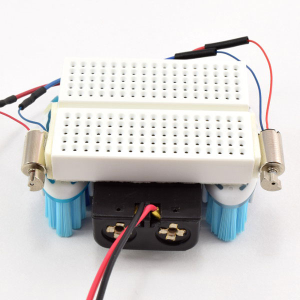
Now, you might be thinking, "I thought this was a robotics project, so what do insect behaviors have to do with robots?" It turns out that sometimes, engineers like to design robots based on things they see in nature. For example, there are robots that use legs to run like animals and robots that fly by flapping their wings like a bird. Robots that are modeled after animals are called biologically inspired robots (or "bio-inspired" for short). In this project, you will build your own miniature, bio-inspired robot, like the one in Figure 1: a robot "bug" that will automatically drive toward a light source, just like some real bugs do! The robot is a type of bristlebot, which gets its name because it uses bristles from a toothbrush as feet.
Figure 1. A light-following bristlebot.
So, how do you get a robot to drive toward a light? The robot will use two light sensors, which are special electronic parts that are sensitive to light. The light sensors are connected to an electrical circuit, or collection of electronic components that serve a specific purpose, and acts like the robot's "brain." The circuit in your robot will control two vibrating motors, which is like how an insect's brain controls its muscles. The motors will make the robot vibrate and buzz along, and can also steer the robot left and right. All of this might sound complicated, but do not worry! The Procedure for this project will show you, step-by-step, how to build the robot and assemble the circuit, and you will learn about the different circuit parts as you go along. (For a detailed explanation of how the circuit works, including a circuit diagram, see the Help section). You can also check out the Science Buddies Electricity, Magnetism, & Electromagnetism Tutorial to learn more about electricity in general.
Terms and Concepts
These terms are used in the Introduction:
- Phototaxis
- Biologically inspired (or bio-inspired)
- Bristlebot
- Light sensor
- Circuit
- Motor
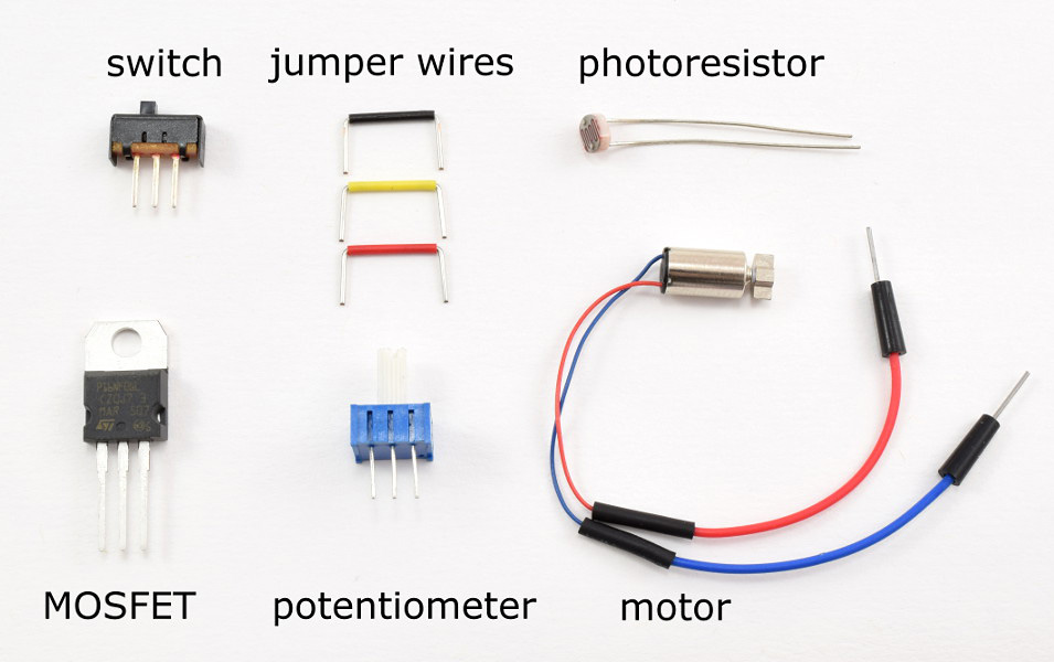
These circuit terms are referenced in the Procedure:
- Breadboard
- Jumper wires
- Potentiometer
- Resistor
- Switch
- MOSFET
- Photoresistor
These terms are used in the advanced explanation in the Help section:
- Voltage divider
- Ohm's law
- Terms related to the MOSFET:
- Gate
- Drain
- Source
- Threshold voltage
- Saturation
- N-channel MOSFET
- P-channel MOSFET
Questions
- What is phototaxis? What are the different kinds of phototaxis?
- What are some examples of different types of biologically inspired robots? Hint: Do an internet search for "biologically inspired robot," or think of an animal and do a search for that type of robot, such as a "cheetah robot")
- What are the main parts of the light-tracking bristlebot, and how are they similar to the parts of an insect?
- How is the light-tracking bristlebot able to steer left and right?
Bibliography
These references will be useful if you are just starting to learn about circuits and electronics:
- Grusin, M. (n.d.). What is a Circuit? SparkFun Electronics. Retrieved July 31, 2014.
- Science Buddies Staff. (n.d.). How to Use a Breadboard. Retrieved June 23, 2016.
- Sarafan, R. (2011, December 22). Basic Electronics. Instructables.com. Retrieved June 2, 2014.
These references will be helpful for advanced students who want to learn more about circuits, including the specific circuit concepts used in this project:
- Lindblom, J. (n.d.). How to Read a Schematic. SparkFun Electronics. Retrieved June 2, 2014.
- Taylor, C. (n.d.). Voltage, Current, Resistance, and Ohm's Law. SparkFun Electronics. Retrieved June 2, 2014.
- Lindblom, J. (n.d.). Voltage Dividers. SparkFun Electronics. Retrieved June 4, 2014.
- Storr, W. (2014, June 2). The Mosfet. Electronics Tutorials. Retrieved June 4, 2014.
- Lindblom, J. (n.d.). Resistors. SparkFun Electronics. Retrieved June 19, 2014.
Materials and Equipment 
Recommended Project Supplies
/-/https/www.sciencebuddies.org/cdn/Files/9115/9/bristlebot-advanced-pair-1100.png)
- Advanced Bristlebots Robotics Kit, available from our partner Home Science Tools®. You will need these items from the kit:
- Mini breadboard
- 2xAAA battery holder
- AAA batteries (2)
- Mini vibration motors (2)
- Toggle switch
- 10 kΩ potentiometers (2)
- N-channel MOSFETs (2)
- Photoresistors (2)
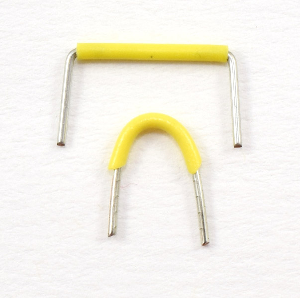
- 1/2 inch yellow jumper wires (2)
- 1/2 inch red jumper wire
- 1/2 inch black jumper wire
- 3/4 inch black jumper wires (2)
- 1 inch black jumper wires (2)
- Note: This kit also contains materials to build a Build a Solar-Powered Bristlebot
- You will also need to gather these items, not included in the kit:
- Identical toothbrushes with slanted bristles (2)
- Scissors or wire cutters
- Double-sided foam tape
- Optional: Craft materials to decorate your robot (such as googly eyes, colorful pipe cleaners, etcetera)
- Flashlight
- Smooth surface for testing the robot (the toothbrush bristles will get stuck on rough surfaces)
- Lab notebook
Disclaimer: Science Buddies participates in affiliate programs with Home Science Tools®, Amazon.com, Carolina Biological, and Jameco Electronics. Proceeds from the affiliate programs help support Science Buddies, a 501(c)(3) public charity, and keep our resources free for everyone. Our top priority is student learning. If you have any comments (positive or negative) related to purchases you've made for science projects from recommendations on our site, please let us know. Write to us at [email protected].
Experimental Procedure
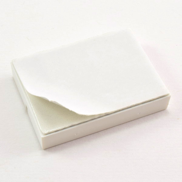
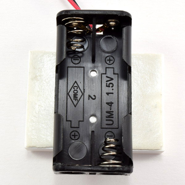
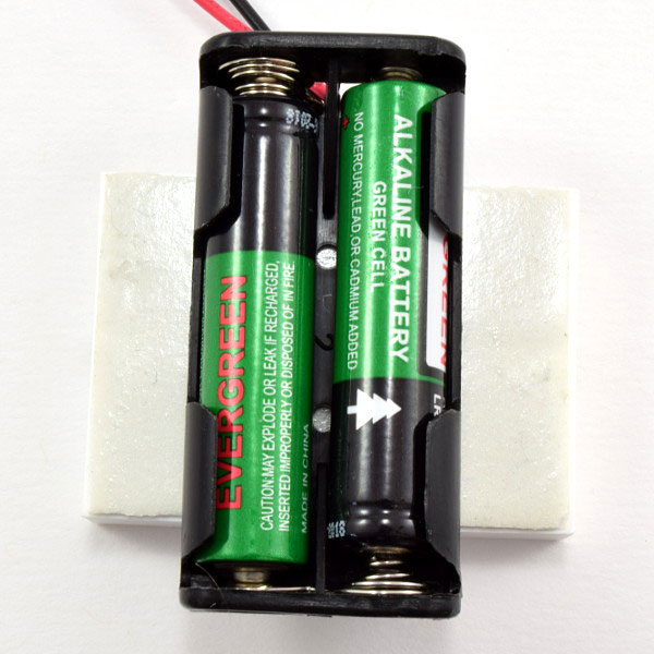
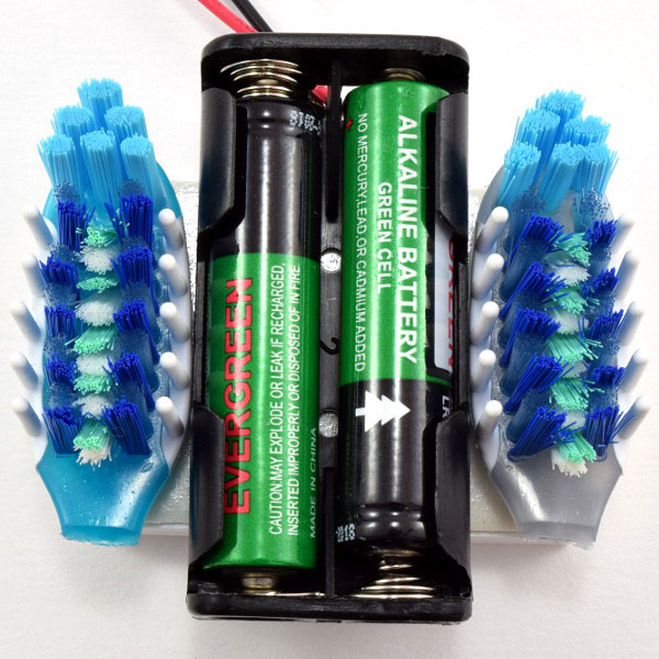
Assembling Your Robot's Body
Follow the steps in this slideshow to build your robot's body. Make sure you read the captions below each image for important notes about each step. You can also watch this video that shows how to assemble the robot.
/-/https/www.sciencebuddies.org/cdn/Files/8163/9/chassis-slideshow-7.jpg)
/-/https/www.sciencebuddies.org/cdn/Files/8157/9/chassis-slideshow-1.jpg)
/-/https/www.sciencebuddies.org/cdn/Files/8158/9/chassis-slideshow-2.jpg)
/-/https/www.sciencebuddies.org/cdn/Files/8159/9/chassis-slideshow-3.jpg)
/-/https/www.sciencebuddies.org/cdn/Files/8160/9/chassis-slideshow-4.jpg)
/-/https/www.sciencebuddies.org/cdn/Files/8161/9/chassis-slideshow-5.jpg)
/-/https/www.sciencebuddies.org/cdn/Files/8162/9/chassis-slideshow-6.jpg)
Slideshow with step-by-step instructions viewable online.
Assembling Your Robot's Circuit
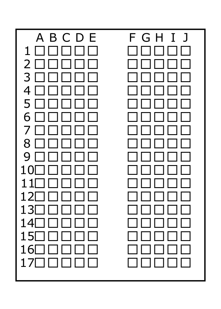
If you have never used a breadboard before, you should refer to the Science Buddies resource How to Use a Breadboard for Electronics and Circuits before you continue.
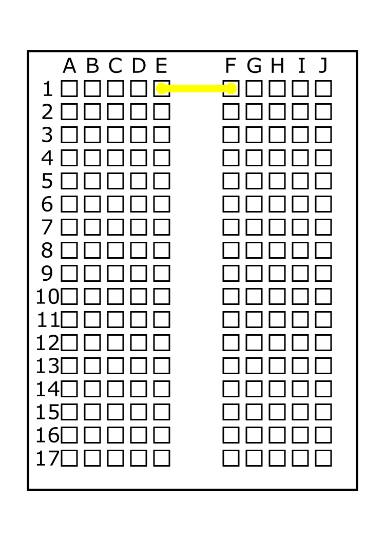
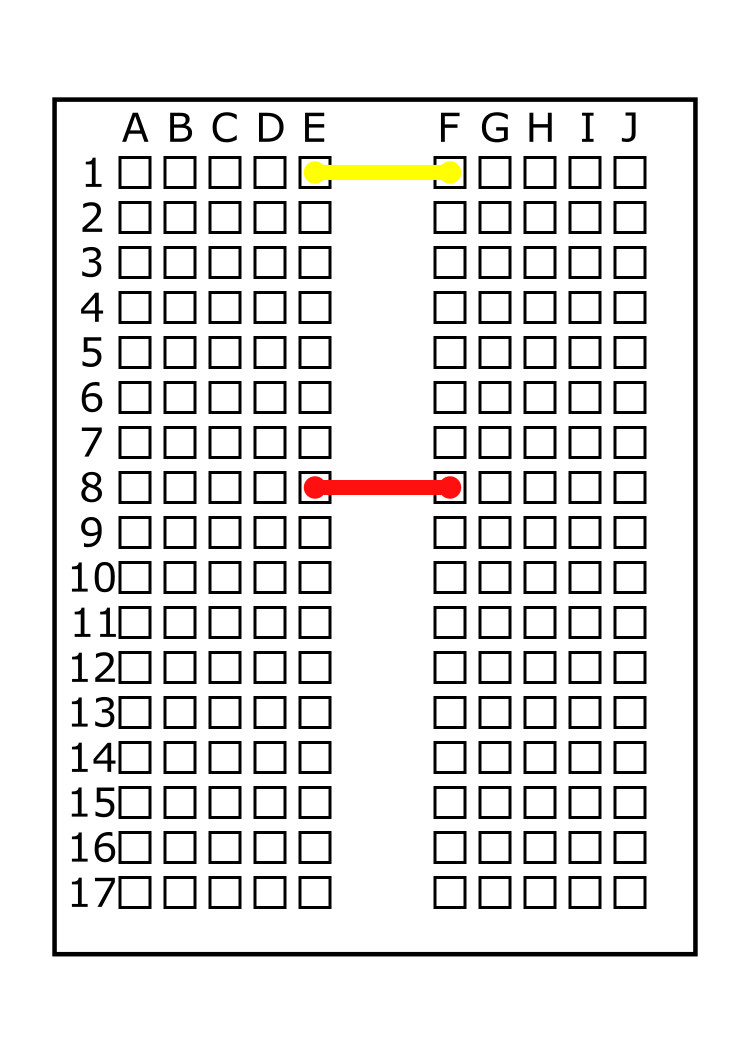
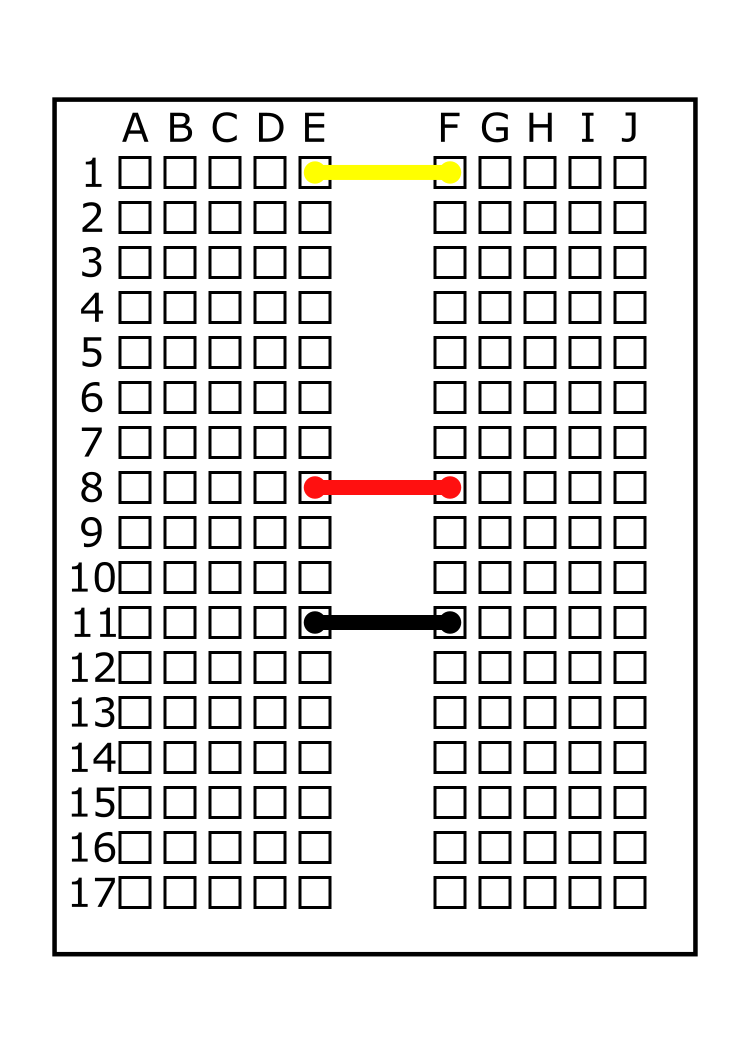
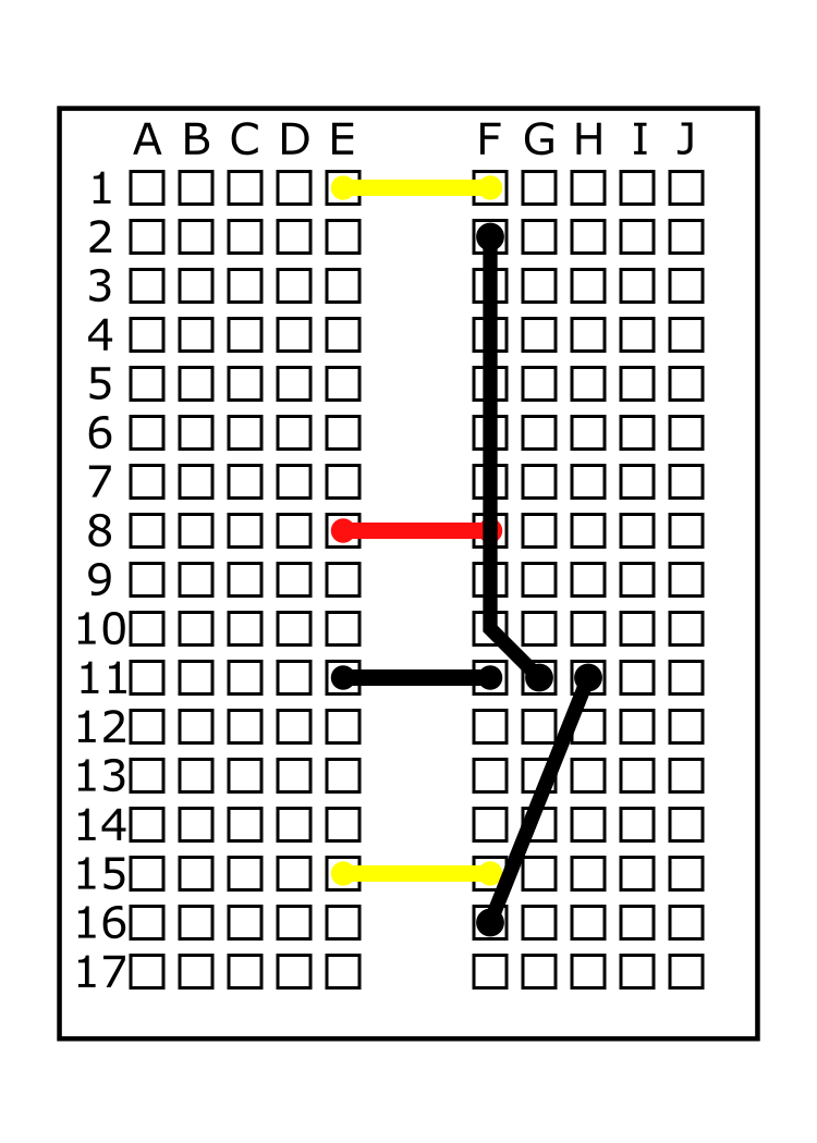
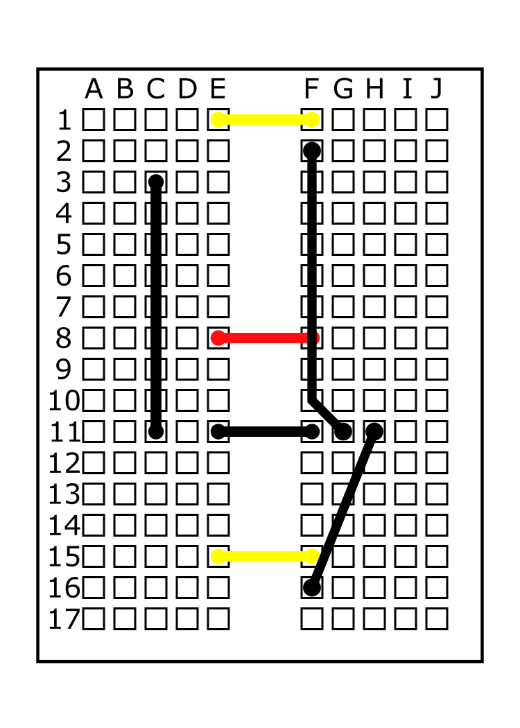
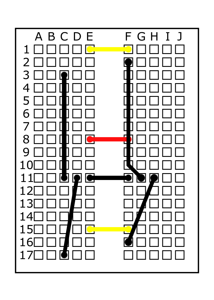
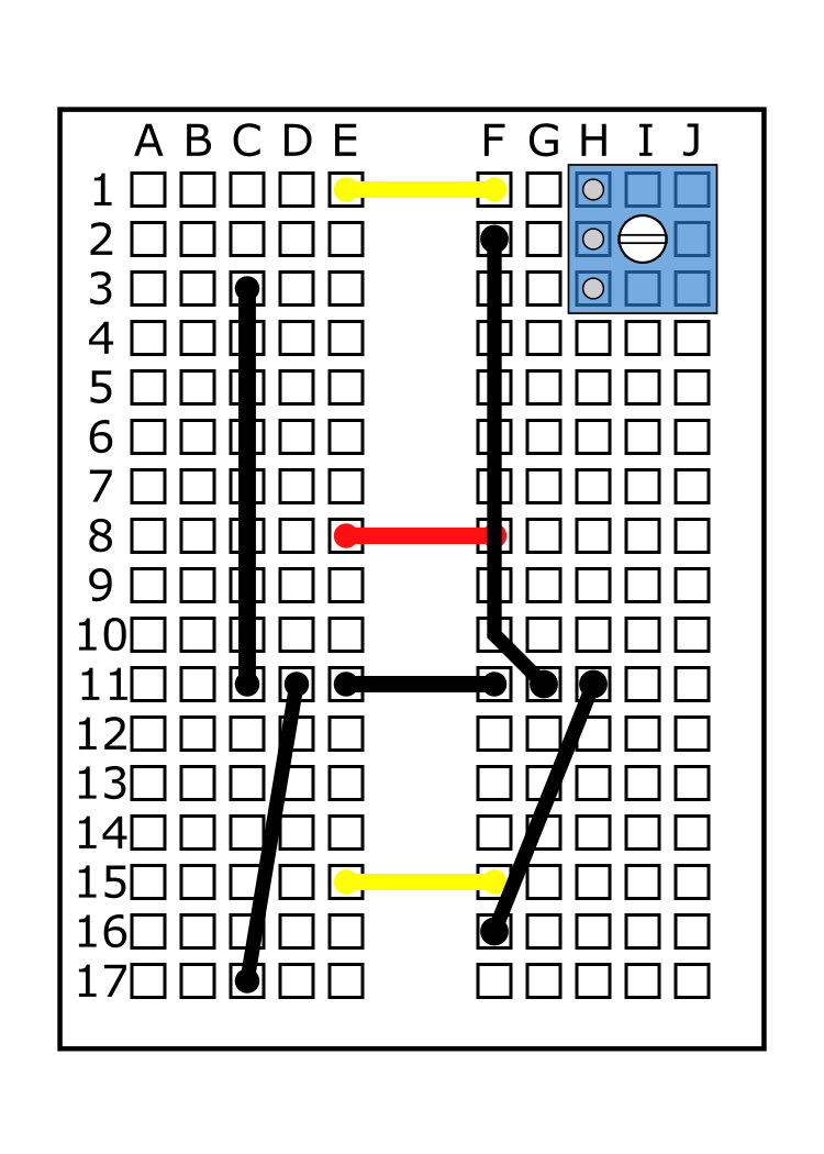
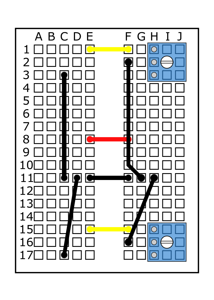
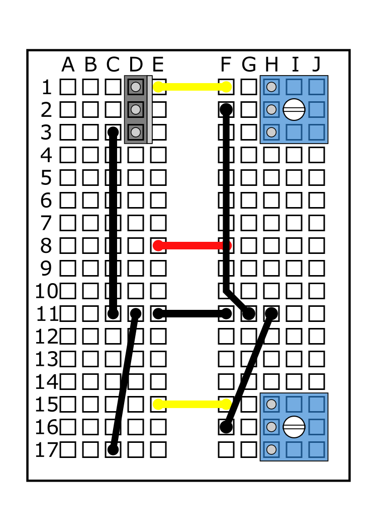
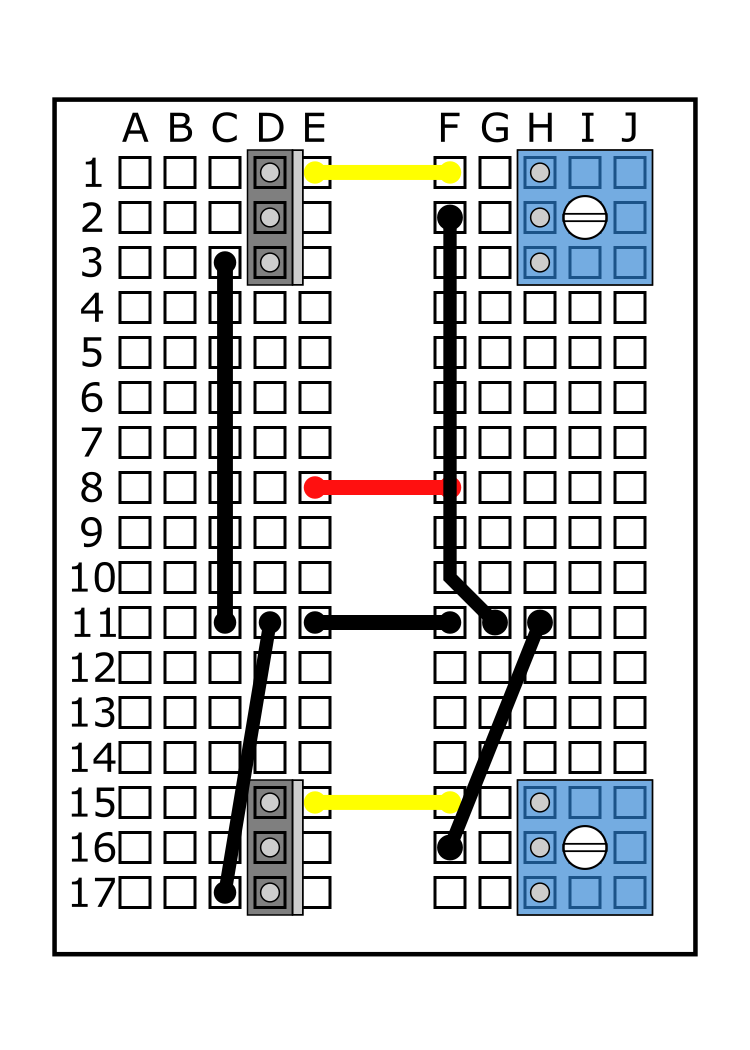
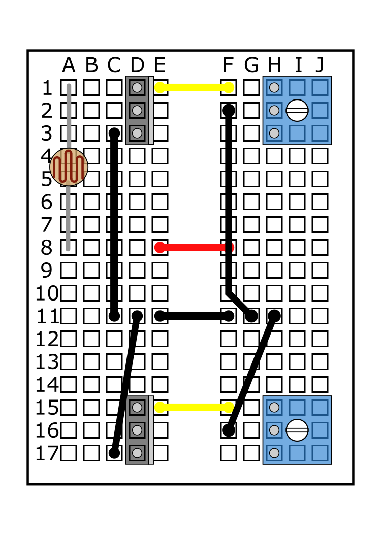
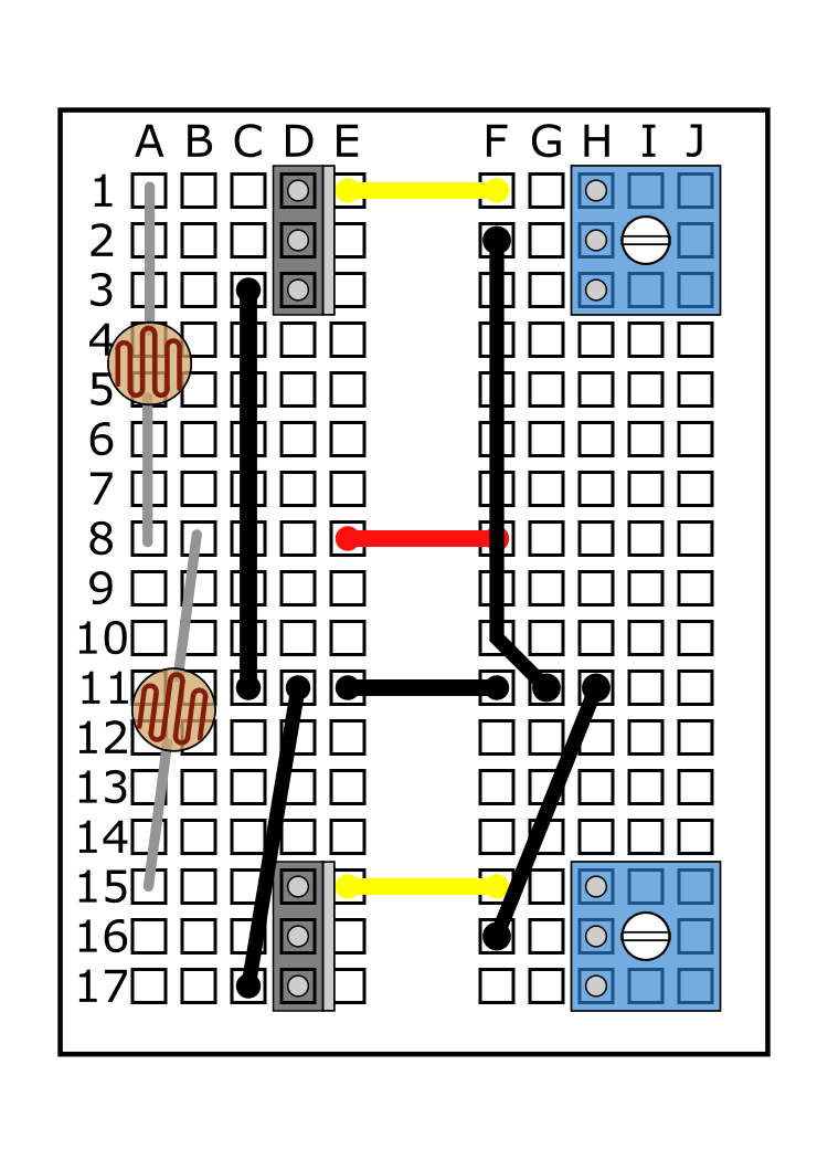
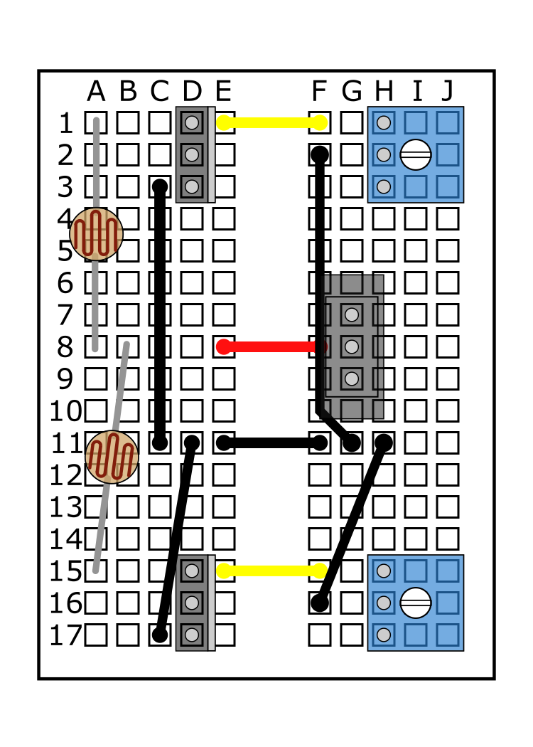
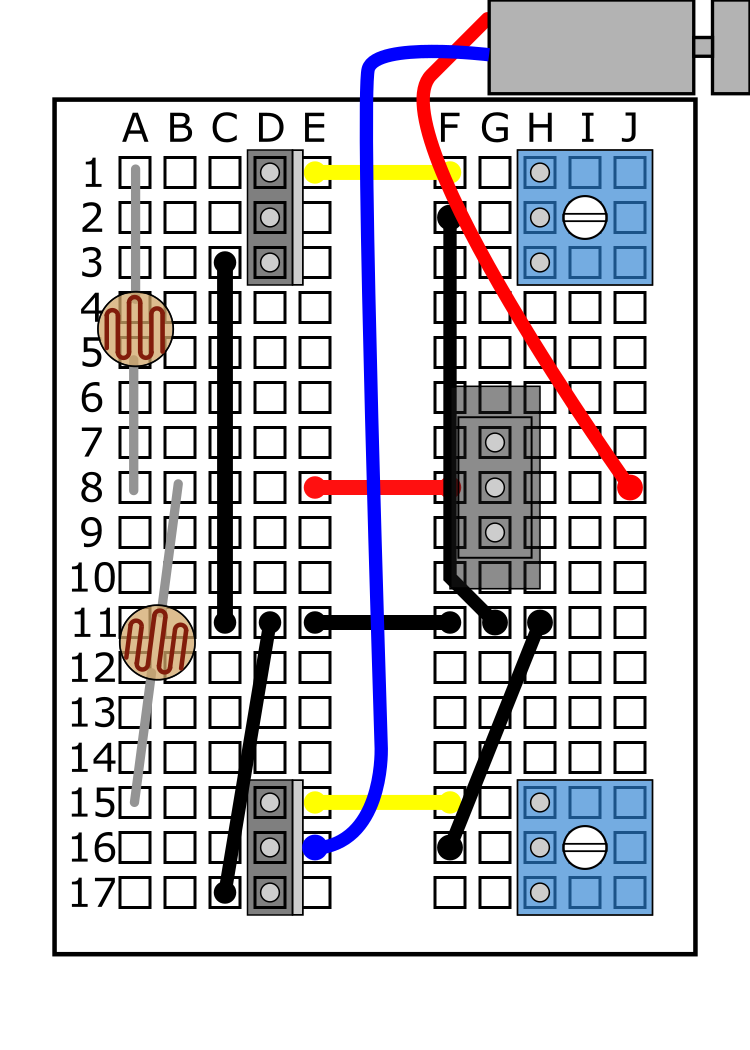
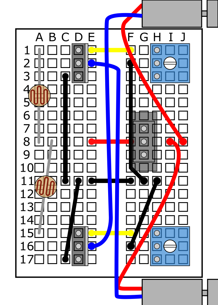
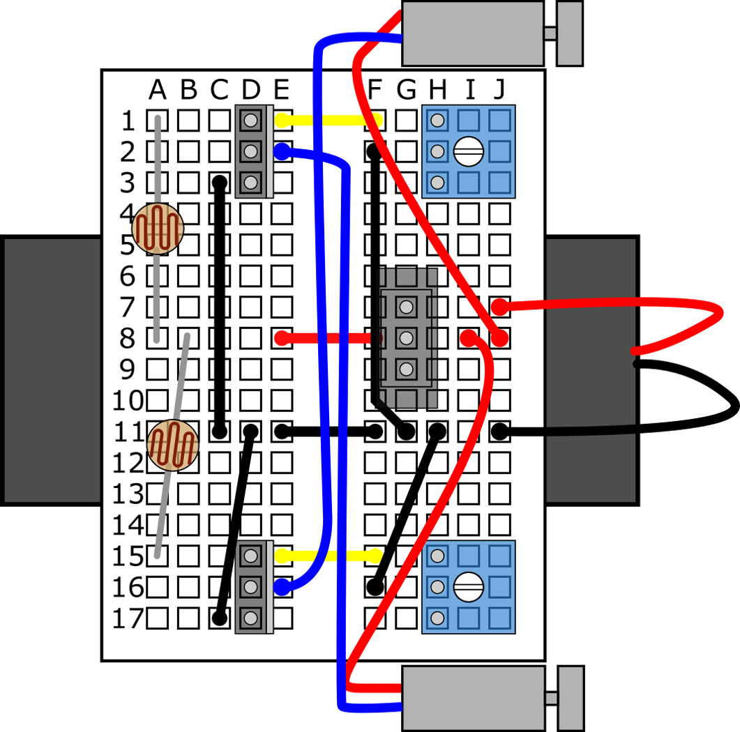
Build the circuit on your robot's breadboard by following along with the slideshow. Make sure you read the captions below each image for important notes about each step. You can also skip to this part of the video to see the circuit assembly steps.
/-/https/www.sciencebuddies.org/cdn/Files/8186/6/slideshow-circuit-22.png)
/-/https/www.sciencebuddies.org/cdn/Files/8165/6/slideshow-circuit-1.jpg)
/-/https/www.sciencebuddies.org/cdn/Files/8166/9/slideshow-circuit-2.jpg)
/-/https/www.sciencebuddies.org/cdn/Files/8167/6/slideshow-circuit-3.jpg)
/-/https/www.sciencebuddies.org/cdn/Files/8168/6/slideshow-circuit-4.png)
/-/https/www.sciencebuddies.org/cdn/Files/8169/6/slideshow-circuit-5.png)
/-/https/www.sciencebuddies.org/cdn/Files/8170/6/slideshow-circuit-6.png)
/-/https/www.sciencebuddies.org/cdn/Files/8171/6/slideshow-circuit-7.png)
/-/https/www.sciencebuddies.org/cdn/Files/8172/6/slideshow-circuit-8.png)
/-/https/www.sciencebuddies.org/cdn/Files/8173/6/slideshow-circuit-9.png)
/-/https/www.sciencebuddies.org/cdn/Files/8174/6/slideshow-circuit-10.png)
/-/https/www.sciencebuddies.org/cdn/Files/8175/6/slideshow-circuit-11.png)
/-/https/www.sciencebuddies.org/cdn/Files/8176/6/slideshow-circuit-12.png)
/-/https/www.sciencebuddies.org/cdn/Files/8177/6/slideshow-circuit-13.png)
/-/https/www.sciencebuddies.org/cdn/Files/8178/6/slideshow-circuit-14.png)
/-/https/www.sciencebuddies.org/cdn/Files/8179/6/slideshow-circuit-15.png)
/-/https/www.sciencebuddies.org/cdn/Files/8180/6/slideshow-circuit-16.png)
/-/https/www.sciencebuddies.org/cdn/Files/8181/6/slideshow-circuit-17.png)
/-/https/www.sciencebuddies.org/cdn/Files/8182/6/slideshow-circuit-18.png)
/-/https/www.sciencebuddies.org/cdn/Files/8183/6/slideshow-circuit-19.png)
/-/https/www.sciencebuddies.org/cdn/Files/8184/6/slideshow-circuit-20.png)
/-/https/www.sciencebuddies.org/cdn/Files/8185/6/slideshow-circuit-21.png)
Slideshow with step-by-step instructions viewable online.
Testing Your Robot
To learn how to use your robot, you can watch this video, or follow the steps below. If you run into trouble and your robot does not work as described, the video also includes troubleshooting information, and you can check out the FAQ section of this project.
- Make sure you slide your robot's power switch down toward row 17 when holding the robot, as shown in the circuit assembly slideshow. This is the "off" position.
- Bend the photoresistors' leads so they face up, outward, and slightly away from each other. The photoresistors sense light and help your robot steer left and right. If they are directly next to each other, they will have trouble sensing different amounts of light.
- Turn the white knobs on both of your potentiometers all the way counter-clockwise.
- Turn the robot on by sliding the power switch up.
- Slowly start turning one of the potentiometers clockwise. You should eventually see one of the motors start to spin, and feel and hear the robot vibrate. Make sure your hands are not blocking light to the photoresistors when you do this.
- Turn the potentiometer back down until the robot just stops vibrating.
- Repeat steps 5–6 with the other potentiometer.
- You have just set the robot's sensitivity to light slightly below the ambient light levels in the room (for more details on how this works, see this question in the FAQ). That means that the motors will only spin if they are exposed to brighter light. You can test this by holding the robot directly up to a lamp.
- Now, if you aim a flashlight directly at the robot's photoresistors (not at the ground in front of the robot), it should move, and you should be able to steer it left and right by aiming at only one photoresistor at a time.
- Practice steering your robot around with a flashlight. It might not work perfectly at first, and may require some tinkering on your part. If your robot has trouble steering:
- Try adjusting the aim of the photoresistors. Make sure they are not too close together or it will be difficult to make the robot steer left and right; or too far apart or it will be difficult to make the robot go straight.
- Try adjusting the potentiometers to change the robot's sensitivity to light.
- If your robot has severe steering problems (for example, it will only turn sharply to one side), make sure the toothbrushes are mounted symmetrically.
- If your robot does not work at all (does not respond to changes in light, or moves all the time regardless of light), there is probably something wrong with your circuit. See the FAQ section for help.
- Slide the power switch back to the "off" position to save battery power when you are not using your robot.
/-/https/i.ytimg.com/vi/zd5auiUpoMk/maxresdefault.jpg)
Using Your Robot in a Science Fair Project
If you want to enter your robot in a science fair, just building it might not be enough. How could you use your robot to do an experiment? Here are a few ideas:
- Build a maze or obstacle course for your robot and challenge people to guide the robot through it using a flashlight. Is there a learning curve to operating the robot? Do people complete the maze faster on subsequent runs?
- Measure how fast the robot moves when exposed to different intensities of light.
- Measure how fast the robot moves on different surfaces.
- Measure how fast the robot moves or how easy it is to steer with different types of toothbrushes for feet. Be very careful when peeling toothbrush heads off the bottom of the breadboard, as this can ruin the sticky tape if you do it too quickly.
- If you have access to a multimeter, use it to measure the resistance of the potentiometers. How do they affect the robot's speed when exposed to a constant source of light? How does the threshold at which the motors start spinning change?
Explore More!
Looking for more robot fun? Explore the World of Robotics with This Suite of Projects!
Troubleshooting
For troubleshooting tips, please read our FAQ: Build a Light-Tracking Bristlebot.
Ask an Expert
Global Goals
The United Nations Sustainable Development Goals (UNSDGs) are a blueprint to achieve a better and more sustainable future for all.
/-/https/www.sciencebuddies.org/cdn/Files/19752/5/E-WEB-Goal-09.png)
Variations
- If you think this robotics project is too complicated and want to start out with something easier, check out these lower-difficulty Science Buddies robotics projects:
- Your Advanced Bristlebot Kit also contains parts to make a Build a Solar-Powered Bristlebot. Can you figure out how to combine the two circuits to make a solar-powered, light-following bristlebot?
- The robot in this project is set up to drive toward light (positive phototaxis). Can you change the robot so it moves away from light (negative phototaxis)?
- Can you build a line-following bristlebot that automatically follows a dark line on the floor? See the Science Buddies project Build a Zippy Line-following Robot (BlueBot Project #3) for a circuit design that will allow a robot to automatically follow a line. The circuit is designed for a larger robot with a bigger breadboard (and a 4xAA battery pack instead of a 2xAAA battery pack), so you will need to make some changes to make it fit on your robot.
- If you want to build a bigger, faster light-following robot, check out the Science Buddies project Build a Speedy Light-Tracking Robot (BlueBot Project #2).
Explore More!
Looking for more robot fun? Explore the World of Robotics with This Suite of Projects!
Frequently Asked Questions (FAQ)
- Why are my motors not spinning at all?
- I think my motors are broken. How can I check?
- Why does my robot not drive forward at all?
- Why does my robot only turn in one direction?
- Why can I not get my robot to go straight when using the flashlight?
- Why can I not get my robot to turn left and right when using the flashlight?
- How does the light sensor work?
- How does a MOSFET work?
- How does the circuit work? What is the circuit diagram?
- How did you make the breadboard diagrams for this project?
- Double- and triple-check your robot's wiring against the breadboard diagrams provided in the Procedure. Remember that you need to accurately count rows and columns since your breadboard does not have labels printed on it.
- Make sure all the wires are pressed firmly into the breadboard's holes. You should be able to turn your robot upside-down, and even shake it, without anything falling out. A single loose connection can prevent the robot from working.
- Make sure you properly inserted the batteries into the battery holder. The "+" symbols on the batteries should line up with the "+" symbols inside the battery holder.
- Make sure the MOSFETs are facing the right direction. When the robot as oriented as shown in the slideshow in the Procedure, the writing on the MOSFETs should face to the left, and the large metal tabs should face to the right.
- Make sure you turned your robot "on" by sliding the power switch "up," towards row 1 on the breadboard when the robot is oriented as shown in the slideshow.
- Make sure you are holding the robot in a well-lit room or near a bright source of light, like an open window or a lamp. The robot will not work in very dim light.
If your motors do not spin, that does not guarantee that they are broken. You could have the batteries inserted into the battery holder incorrectly. Double check that the "+" symbols on the batteries line up with the "+" symbols inside the battery holder.
- Make absolutely sure you are using toothbrushes with the longest bristles slanted in one direction. If you use toothbrushes with straight bristles, or toothbrushes with equal-length bristles slanted in both directions, the robot will probably not drive forward.
- Make sure you are using two identical toothbrush heads. Even small differences between different types of toothbrush can affect the robot's steering.
- Make sure the toothbrush heads are mounted straight and parallel to each other. If one or both of the toothbrushes are mounted crooked, this could prevent the robot from going straight.
- When viewing the robot from behind, turn the left potentiometer all the way down (counterclockwise) and the right potentiometer all the way up (clockwise).
- Put the robot down on a flat surface in a well-lit area. It should turn to the right (drive in clockwise circles).
- Now, reverse the potentiometers. Turn the left potentiometer all the way up (clockwise), and the right potentiometer all the way down (counterclockwise).
- Put the robot down again. It should turn to the left (drive in counterclockwise circles).
If your robot only turns in one direction, and does not turn in the other direction at all, then there is probably a mistake in your wiring for one half of your circuit. Double-check the diagrams in the Procedure to make sure your robot matches them. If the robot turns more sharply in one direction than the other when you do this, the problem is probably that one or both of your toothbrushes are mounted crookedly. This can cause the robot to veer off to one side. Make sure your toothbrush heads are mounted straight and parallel to each other.
In order to make a light sensor, the photoresistor and potentiometer are combined to make a voltage divider. A voltage divider is a simple circuit made from two resistors, R1 and R2 (Figure 2). It takes an input voltage (Vin) and outputs a different voltage (Vout), according to Equation 1 (which can be derived based on Ohm's law—see the Bibliography):
Equation 1:
- Vin is the input voltage in volts (V).
- Vout is the output voltage in volts (V).
- R1 is the first resistance in ohms (Ω).
- R2 is the second resistance in ohms (Ω).
/-/https/www.sciencebuddies.org/cdn/Files/6218/15/resistive-voltage-divider.png)
Figure 2. Circuit diagram for a voltage divider.
In your circuit, the photoresistor will be R1 and the potentiometer will be R2. Remember that the resistance of a photoresistor decreases when it is exposed to bright light. From Equation 1, we can see that when R1 is very large (R1 >> R2), Vout gets very small (Vout << Vin). When R1 is very small (R1 << R2), Vout is roughly equal to Vin (Vout ≅ Vin). This means that the light sensor outputs a high voltage when it detects light, and a low voltage when it does not.
Figure 3 shows a simplified explanation of how a MOSFET works. A voltage is applied to the gate pin in order to control the flow of current between the drain and source pins. When the voltage between the gate and source pins (VGS) is below a certain limit, called the threshold voltage (Vth), no current flows. When VGS exceeds Vth, the MOSFET begins to conduct, allowing current to pass through. This is what allows you to use the gate voltage of a MOSFET to turn a DC motor on and off. For this robot, the MOSFET's gate voltage is controlled by the voltage divider.
/-/https/www.sciencebuddies.org/cdn/Files/6217/15/MOSFET-operation.png)
Figure 3. Simplified explanation of a MOSFET's operation.
The exact description of how a MOSFET works is more complicated than this. As VGS increases past Vth, the current through the MOSFET will continue to increase. Eventually the MOSFET will reach saturation, where no additional current can flow, even if VGS continues to increase. The MOSFET's behavior will also depend on the type of load to which it is attached. The MOSFET used in this project is an N-channel MOSFET, which requires a positive gate voltage to turn on. A P-channel MOSFET requires a negative gate voltage to turn on. Advanced users can refer to the Bibliography for more information on MOSFETs.
/-/https/www.sciencebuddies.org/cdn/Files/6471/8/light-follower-bristlebot-circuit-diagram.png)
Figure 4. A complete circuit diagram for the light-following robot.
The circuit diagram might look confusing at first, but it just consists of things you have already read about. Let us just look at the left-hand side of the circuit (the same explanation applies to the right-hand side):
- The battery pack supplies a voltage Vbatt to the circuit. For this project, you will use two AAA batteries, which provide about 3 V.
- The switch controls whether or not the battery pack's positive terminal is connected to the circuit. When the switch is open, V1 is "floating" (not connected to anything), so the circuit has no power. When the switch is closed, V1 is equal to the battery voltage.
- The photoresistor (R1) and potentiometer (R2) form a voltage divider. The input to this voltage divider is V1, and the output is V2.
- The potentiometer can be used to tune the voltage divider's output (can you figure this out by examining how Equation 1, above, depends on R2?). This allows you to adjust the robot's sensitivity to ambient light levels.
- The output of the voltage divider is connected the input (the gate) of the MOSFET. The source of the MOSFET is connected to ground (0 V). So, for this circuit, VGS = V2. When V2 exceeds the threshold voltage Vth, the MOSFET will turn "on."
- The motor is connected between the positive voltage supply and the MOSFET's drain pin. When the MOSFET is "off," the drain pin's voltage is close to the battery voltage, so no current can flow through the motor. When the MOSFET is "on," the drain pin's voltage drops, allowing current to flow through the motor, into the MOSFET's drain pin, then out of its source pin to ground.
Careers
If you like this project, you might enjoy exploring these related careers:
/-/https/careerdiscovery.sciencebuddies.org/cdn/Files/1725/18/4161_Michelle_Easter_and_Curiousity_Clone.jpg)
/-/https/careerdiscovery.sciencebuddies.org/cdn/Files/1731/17/iStock-1187291213.jpg)
/-/https/careerdiscovery.sciencebuddies.org/cdn/Files/17365/4/manufacturing-technician-main-Stock-1140837585.jpg)
/-/https/careerdiscovery.sciencebuddies.org/cdn/Files/1450/21/iStock-1227179796.jpg)
/-/https/careerdiscovery.sciencebuddies.org/cdn/Files/1223/17/iStock-971549326.jpg)
Contact Us
Our kits are developed in partnership with Home Science Tools®. If you have purchased a kit for this project, Home Science Tools® is pleased to answer any questions not addressed by the FAQ above.In your email, please follow these instructions:
- Include your Home Science Tools® order number.
- Please describe how you need help as thoroughly as possible:
Examples
Good Question I'm trying to do Experimental Procedure step #5, "Scrape the insulation from the wire. . ." How do I know when I've scraped enough?
Good Question I'm at Experimental Procedure step #7, "Move the magnet back and forth . . ." and the LED is not lighting up.
Bad Question I don't understand the instructions. Help!
Good Question I am purchasing my materials. Can I substitute a 1N34 diode for the 1N25 diode called for in the material list?
Bad Question Can I use a different part?
Contact Support

/-/https/img.youtube.com/vi/OEkw3F7RZ3w/0.jpg)
/-/https/img.youtube.com/vi/TFGeefF82o8/0.jpg)
/-/https/img.youtube.com/vi/tXWv9JbmnKs/0.jpg)