Page 1 of 1
Help with simulating a truss!
Posted: Sun Dec 28, 2014 10:22 pm
by kac_love
On the website
http://pages.jh.edu/~virtlab/bridge/bridge.htm
I found myself stuck on how to create a right isosceles truss and a 30-60-90. Could anyone help me? Like what would it look like? The truss has to be stable.
Thank you. Please reply as soon as possible. I would like to have the experimenting part done by January 8.
Below is the link to a screenshot of what I tried to do for the right isosceles:
http://s7.postimg.org/ssqek1nhn/Screen_ ... M_copy.jpg
Re: Help with simulating a truss!
Posted: Mon Dec 29, 2014 6:01 am
by bfinio
Hi kac_love,
Are you doing a specific Science Buddies project, and if so can you link to it? We recently updated this project:
https://www.sciencebuddies.org/science- ... p011.shtml
to use a bridge design program called ForceEffect, because many students were having trouble running programs based on Java applets due to browser security settings (I clicked the link you sent, and the bridge designer doesn't work in my browser, so unfortunately I can't help there). However, ForceEffect lets you design trusses, apply forces to your truss/bridge, and see reaction forces at different points and forces within the beams, so I imagine it's pretty similar to Bridge Designer. It's available as an Android or iOS app and you can also run it in Chrome on a desktop:
https://play.google.com/store/apps/deta ... ZpdGllcyJd
https://itunes.apple.com/us/app/autodes ... ?ls=1&mt=8
Do you understand what right isosceles and 30-60-90
triangles are? A right isosceles or 30-60-90 truss is just a truss made up of lots of that specific kind of triangle. Do a google image search for "right isosceles truss" and "30-60-90 truss" and you will see some examples.
Hope that helps. Thanks,
Ben
Re: Help with simulating a truss!
Posted: Mon Dec 29, 2014 4:18 pm
by kac_love
As it says on the side, I'm doing the following project:
https://www.sciencebuddies.org/science- ... p006.shtml
I understand what the triangles are, and I web searched examples of each of the truss, but I couldn't find any. Thank you for helping Ben.
Re: Help with simulating a truss!
Posted: Mon Dec 29, 2014 7:21 pm
by kac_love
I mostly need help with the 30-60-90 as I fixed the other truss (right isosceles). What is it supposed to look like and how am I supposed to make it stable?
Re: Help with simulating a truss!
Posted: Tue Dec 30, 2014 6:24 am
by bfinio
kac_love -
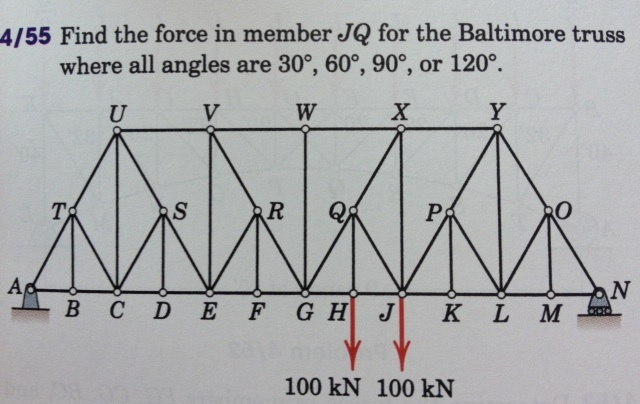
I searched "30-60-90 truss" and this is the first image that came up:
http://media.cheggcdn.com/media%2Fb52%2 ... 6QpTtZ.png
I think if you drew a horizontal line from point T to point O, and then "chopped off" the top half of the bridge, you would be left with a 30-60-90 truss. Every remaining triangle would be 30-60-90.
Here's another example that looks like it is made up of all 30-60-90 triangles:
https://lh6.ggpht.com/RV3NPxT3s4vaKdsz6 ... v0A-I=h900
Re: Help with simulating a truss!
Posted: Tue Dec 30, 2014 1:51 pm
by kac_love
Thank you so much. I'll have to redesign my 30-60-90.
Where do I place the loads, and fixed nodes/horizontal rolling nodes so it's stable? I know you don't have access to the website linked for the simulation, but I wasn't sure what exactly it meant (see screenshots below) for the compression and the tension (they are highlighted in red and blue)
http://s17.postimg.org/y4xgwwi9r/equilateral.png <<< this is the equilateral
http://s21.postimg.org/ldxkwoh87/isosceles.png <<< this is the right isosceles
Re: Help with simulating a truss!
Posted: Tue Dec 30, 2014 3:15 pm
by bfinio
Hi kac_love,
I want to make sure I understand your questions, so I'll try to answer them separately:
1. "Where do I place the loads" - I'm not sure - does the project tell you to put the loads in a specific place?
2. "Where do I place...the fixed nodes/horizontal rolling nodes so it's stable" - look closely at the images you sent. They both have a fixed node in the bottom left (yellow dot), and a rolling node in the bottom right (red dot). That means the bridge is "stable" in the sense that if it had rolling nodes on both sides, it would be free to roll to the left or right; and if it had fixed nodes on both sides, it would be "overconstrained" and the program would be unable to solve for the forces.
3. "I wasn't sure exactly what it meant...for the compression and the tension" - do you understand what compression and tension mean in general? Pick up any nearby object like a pencil, and hold one end in each hand. If you pull on both ends, the pencil is in tension. If you press on both ends, the pencil is in compression. That's pretty simple to understand for a single long, narrow object. With a truss (which is made up of many long, narrow beams), it gets more complicated. Depending on how the truss is designed, when a load is applied to the bridge, some of the beams will be in compression and some of them will be in tension. This is what the program is showing you with the red and blue beams.
Re: Help with simulating a truss!
Posted: Tue Dec 30, 2014 4:39 pm
by kac_love
1. No, it doesn't. It only says, "Use the 'Add loads' button to apply a force to your truss. Click on a node and drag. The magnitude of the force increases as you drag further (indicated by number). The direction of the force is indicated by the arrow."
2. Okay, that makes sense. From what I'm understanding, I need to put the fixed node on one side, and the horizontal rolling node on the other so it balances out to be stable.
3. Okay, do the numbers of indicate how much it's in compression or tension?
_
Also, I reconstructed the 30-60-90 to the design the image you linked to. However, when I tried to calculate it, this was the result:
http://s13.postimg.org/f0yeqfhef/attempt30_60_90.png
The simulation was unable to find a solution; is there a specific reason why?
Re: Help with simulating a truss!
Posted: Tue Dec 30, 2014 11:49 pm
by kac_love
Alleluia! I made a discovery, though you may know this.
On the website for the simulation, there should have been a webpage, that explained some of the structure and parts of trusses. After reading a little more into it, I found the equation helpful:
M+3=2N
Where M represents the number of members, and N represents the number of nodes. Finding this, I decided to go back and try to construct a stable 30-60-90 truss. I, however, am having trouble making this statement/equation valid (so that's why there's no solution) How do I construct a truss with the number of members and nodes satisfying the equation?
I will continue to try to make this work, and start constructing the truss.
Re: Help with simulating a truss!
Posted: Wed Dec 31, 2014 6:56 am
by bfinio
kac_love,
I've never seen that equation before, so I can't provide specific advice. I would suggest that you continue searching for 30-60-90 truss designs online and try replicating those. I did some googling and it looks like there are several names for trusses that could be made out of 30-60-90 triangles, including Howe truss, Pratt truss, and Warren truss. Googling those names might give you more ideas. Look at page 2 of this PDF to see what I mean:
http://www.engr.uky.edu/~gebland/CE%203 ... ctures.pdf
Hope that helps.
-Ben
Re: Help with simulating a truss!
Posted: Fri Jan 02, 2015 12:03 am
by kac_love
Okay I'll try looking at that. Thank you for the help, I'll let you know if I can't figure it out
Quick question- would this count as a bridge truss?
Re: Help with simulating a truss!
Posted: Fri Jan 02, 2015 6:22 am
by bfinio
In my experience truss structures
usually refer to bridges. Technically I think a bridge truss is one that only has supports on both ends and carries a load in the middle, so yes, what you are designing in this project is a bridge truss. There are other uses for trusses, like cranes or the Eiffel tower:
http://s.hswstatic.com/gif/tower-crane12.jpg
http://upload.wikimedia.org/wikipedia/c ... ommons.jpg
But that isn't what you're designing here.
Re: Help with simulating a truss!
Posted: Wed Jan 07, 2015 5:40 pm
by bradleyshanrock-solberg
Not much help for your experiment, but if your'e interested - trusses are used in nearly every kind of construction, including things as mundane as a gate (that diagonal cross-bar inside the rectangular frame...turns it into two trusses, adds greatly to the strength and stiffness of the gate, which without it might sag and drag on the ground)
The triangle form is a convenient way to redistribute force, and its use goes back thousands of years. Bridges get used as an example mostly because the truss is very visible (you're either using a truss, an arch or some kind of suspension, those are your basic options, unless the bridging material is so strong it can just lie flat, like a log crossing a creek).