Page 1 of 1
Problem with Ultrasonic Levitator
Posted: Thu Dec 11, 2025 8:06 pm
by SahaLevitate123
Hi Science Buddies! I'm doing the ultrasonic levitator project. I've done the circuits and wires and everything but when I upload the code, I can't hold any foam pieces in it. It seems to not have started at all, so I think the problem may the voltage. I'm not sure though, so could you please help me find the problem and solve it? Thanks!
Moderator note:
https://www.sciencebuddies.org/science- ... -levitator
Re: Problem with Ultrasonic Levitator
Posted: Fri Dec 12, 2025 10:02 am
by CarissaP
Hello,
Most of your wiring looks correct, but instead of the orange wire that connects to Vin, you should connect an external power supply (e.g. a 9V battery) to the breadboard. This is likely why the code is not running. Keep in mind that the battery should power the left column, and the yellow wire that connects to the Arduino's 5V power supply should go in the right column to prevent a short circuit. Let us know if this works!
Carissa
Re: Problem with Ultrasonic Levitator
Posted: Fri Dec 12, 2025 10:15 am
by amyCC
In addition to Carissa's note, I want to reiterate that the project is set up to progressively test with increasing voltage. You may find that the best performance will be with more voltage, but that is part of what the project has you test to determine.
Amy
Science Buddies
Re: Problem with Ultrasonic Levitator
Posted: Sat Dec 13, 2025 11:02 pm
by SahaLevitate123
I removed the Vin wire and tested the voltages 5V, 9V, and 12V. It still won't hold any foam balls. Is there a defective piece or bleep? Nothing's overheating. Did I connect bleep wrong? I'm not really sure what's going on to make it not work.
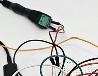
btw I am using 12V in this picture, where I tried connecting the power directly to the Arduino and using Vin pin.
Re: Problem with Ultrasonic Levitator
Posted: Sun Dec 14, 2025 11:44 am
by CarissaP
Hello,
The yellow wire is still connecting the positive column to the Vin. Instead, you need to replace that with an external battery. Where are you connecting the 12V battery? Follow the diagram from the activity:
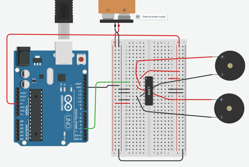
- ultrasonic-levitator-breadboard-diagram.png (210.38 KiB) Viewed 14413 times
- ultrasonic-levitation-circuit.png (36.26 KiB) Viewed 14413 times
Let us know if this works!
Carissa
Re: Problem with Ultrasonic Levitator
Posted: Mon Dec 15, 2025 11:48 am
by bfinio
Hi - I'm jumping in to clarify that technically, when you power the Arduino via the barrel jack, the voltage from the barrel jack does become available on the Vin pin - so powering the breadboard as you have it set up now is technically OK and does make 12V available to the H-bridge.
However, there's some additional circuitry inside the Arduino that can limit the amount of
current available to the breadboard when you do this. It can be better if you don't make the current go "through" the Arduino, and instead connect your external power supply directly to the breadboard (while still powering the Arduino via USB), as suggested in the project instructions that Carissa quoted. You can do that with these barrel jack adapters:
https://www.amazon.com/QLXHBOT-Connecto ... ebuddie-20
Also note that, if you continue reading the instructions, there's an additional step provided to increase the voltage to the transmitters - adding the inverter chip, as shown in Figure 6. That will double the voltage to the transmitters. I don't see the inverter chip in your pictures, so I would recommend adding it.
As for the testing - this can be a tricky project to get working. One thing you can test is just putting a piece of foam on top of a single ultrasonic transmitter. If you see the foam jitter or jump around at all, then you at least know that your circuit is functioning. If the foam doesn't move at all, then there's likely bleep wrong with your circuit. I don't see any wiring errors in the pictures you posted though, again I would recommend 1) directly connecting the external power supply to the breadboard instead of going through the Arduino and 2) adding the inverter chip.
Let us know if you have more questions!
Re: Problem with Ultrasonic Levitator
Posted: Mon Dec 15, 2025 10:28 pm
by SahaLevitate123
Thank you so much, I followed your advice and it finally worked!!! My next step is changing the code so that I can control the frequency of the transmitters. Although your code made it work, when I test this code, it doesn't. Could you see what's the problem with it?
const int pin = 3; // pin number for output to transducers
const int frequency = 40000; // Change to 35000 or 45000 as needed for frequency
const int periodMicroseconds = 1000000UL / frequency;
const int halfPeriod = periodMicroseconds / 2;
void setup() {
pinMode(pin, OUTPUT); // sets PinA (Pin 3) on Arduino to send out output
}
void loop() {
digitalWrite(pin, HIGH); // turns on transducers
delayMicroseconds(halfPeriod); // waits
digitalWrite(pin, LOW); // turns off transducers
delayMicroseconds(halfPeriod); // waits
}
Re: Problem with Ultrasonic Levitator
Posted: Tue Dec 16, 2025 5:52 am
by bfinio
Hi - glad you got it working! Sometimes doing math, especially division, can get a little weird with the Arduino depending on the variable types. I would recommend using serial print commands to print out the periodMicroseconds and halfPeriod variables to make sure you're getting the values you expect. If bleep is going wrong there, you could always do the calculation by hand (or make a spreadsheet) and manually enter the value for the halfPeriod value instead of doing the calculation in the Arduino code.
The other possibility is always that bleep went wrong with the circuit - a loose wire etc - so if bleep stops working, it's always a good idea to go back to known "working" code and make sure that still works.
Re: Problem with Ultrasonic Levitator
Posted: Wed Dec 17, 2025 12:11 am
by SahaLevitate123
I changed the 1000000UL to just 1000000. When I upload this code, I hear tiny sounds coming from the transducers but they don't hold anything. I think they're working, but is there still a problem with the device or do I just need more voltage?
I also have another question. Can these types of transducers handle frequencies from 35 kHz - 45 kHz? If not, what other transmitters are available that work with the same efficacy as these ones?
Re: Problem with Ultrasonic Levitator
Posted: Wed Dec 17, 2025 8:51 am
by bfinio
Hi -
Regarding the frequency - I would recommend re-watching the part of the video about resonant frequency:
https://youtu.be/WcMT-MGv2cw?si=Bxj8G_DHrCQ2kX7V&t=596
When I tested the transmitters, they had a fairly narrow resonant frequency peak in between 40-41kHz. If you go all the way out to 35 or 45kHz, their response is almost zero. So if you would like to test different frequencies, I would suggest testing in much smaller increments, for example starting at 40kHz and only going up or down by 100Hz at a time. It is not a matter of needing more voltage in this case.
If it still isn't working even when you set frequency to 40000, I would still suggest the two things I recommended in my previous post:
1) Go back to the code that was working previously, just to make sure nothing has gone wrong with the circuit
2) Use serial print to print out the values of the periodMicroseconds and halfPeriod variables, just to make sure the calculations are working properly. If you don't know how to do that, let me know and I can help.
Re: Problem with Ultrasonic Levitator
Posted: Thu Dec 18, 2025 9:35 pm
by SahaLevitate123
Although it works with Science Buddies' code, the acoustic levitator simply emits a tiny sound that might mean it is turning on. However, I'm not sure. I'd like to know how to use Serial print to display the variables used. I've changed the code, so please let me know if there's any important problem with it.
const int pin = 3; // pin number for output to transducers
const int frequency = 40000; // Change to 35000 or 45000 as needed for frequency
const int periodMicroseconds = 1000000 / frequency;
const int halfPeriod = periodMicroseconds / 2; // creating variable to turn transmitters on and off for frequency
unsigned int delayTime = halfperiod - 0.76; // subtract decimal to compensate for slight lag of digitalWrite function
void setup() {
//Serial.begin(9600);
pinMode(pin,OUTPUT); // sets PinA (Pin 3) on Arduino to send out output
}
void loop() {
digitalWrite(pin,HIGH); // turns on transducers
delayMicroseconds(delayTime); // waits
digitalWrite(pin,LOW); // turns off transducers
delayMicroseconds(delayTime); // waits
//Serial.println(periodMicroseconds);
//Serial.println(halfPeriod);
}
Re: Problem with Ultrasonic Levitator
Posted: Fri Dec 19, 2025 7:51 am
by bfinio
Hi, two things:
1. You have the serial print code set up right, but it's currently commented out. You need to delete the "//" at the beginning of the Serial.begin and Serial.println lines.
2. The "int" variable type stands for "integer" which means that variable type cannot store or do math with decimals. It only works with whole numbers (0, 1, 2, 3...). Any decimal values just get truncated (1.4 and 1.5 both just become 1). So trying to subtract 0.76 from your halfPeriod variable isn't going to work like you're hoping it will.
If you still can't get the code to work after this, I would recommend going back to the Science Buddies code, and doing the calculations for the delay manually or in a spreadsheet instead of trying to do them in the Arduino code.
Thanks,
Ben
Re: Problem with Ultrasonic Levitator
Posted: Mon Dec 22, 2025 5:46 pm
by SahaLevitate123
Although I failed to make the Serial print thing work, I followed your advice and the code worked! Thanks you so much!!
My code apparently had a delayTime value that induced a frequency outside the transducers' resonant frequency. I set the delayTime simply to 10 as what the video noted. However, I don't know what to change delayTime to for the other frequencies unless I can check what values induce what frequencies. To do that I need an oscilloscope. Where can I find ones that can measure the frequency but are under $40 at least? I keep finding $100+ ones on Amazon

Re: Problem with Ultrasonic Levitator
Posted: Tue Dec 23, 2025 7:02 am
by bfinio
Unfortunately I don't know if it's possible to find an oscilloscope for under $40. Even the cheap "pocket" oscilloscopes I'm aware of are at least $100. Two other options I can think of:
1) Contact a local university to see if anyone in the physics or engineering department will let you have access to an oscilloscope (this is a long shot but it doesn't hurt to ask)
2) If you have an older phone or tablet with a 3.5mm headphone jack (the round plug kind, not the USB-C kind), there are oscilloscope apps where you can use your phone's audio input as an oscilloscope. This risks damaging the phone if you aren't extremely careful, but it could be a cheaper option.
You can also just do your best to calculate the frequency based on the delay time. You know that frequency is the inverse of period:
Frequency (Hz) = 1 / Period (seconds)
And you know that one period of your pulse consists of two digitalWrites and two delayMicroseconds commands. So
Period (microseconds) = 2 * (digitalWriteTime + delayTime)
where digitalWriteTime is however long it takes the digitalWrite command to run in microseconds and delayTime is whatever value you enter for that variable in microseconds. You can't measure exactly how long digitalWrite takes without an oscilloscope, but a quick Google search is telling me it's about 2 microseconds, so you can use that value to start.
Hope that helps!
Re: Problem with Ultrasonic Levitator
Posted: Tue Dec 23, 2025 10:15 pm
by SahaLevitate123
I followed you advice and I calculated the digitalWriteTimes for each frequency I'm using. Thanks for giving this suggestion! I'm pretty sure that I got the right frequencies.
My next step in this is making a parallel circuit where three transducers are on the top and the bottom of the levitator. However, I thought there should be space for more wires to be connected to the H-bridge on the breadboard. Is it even possible for a parallel circuit to be created? If so, how do I do that?
Re: Problem with Ultrasonic Levitator
Posted: Mon Jan 05, 2026 8:50 am
by bfinio
Hi,
Sorry for the delayed reply, I was on vacation for the holidays and am just now catching up on messages.
The way the circuit is designed now, there would be room to connect two more transmitters directly to rows 12 and 15 of the breadboard. If you want to add more in parallel, you would need to run jumper wires from rows 12 and 15 to two other empty rows of the breadboard. For example, you could do:
Jumper wire from row 12 to row 1 (currently empty), and connect additional transmitter positive wires to row 1
Jumper wire from row 15 to row 3 (currently empty), and connect additional transmitter negative wires to row 3
If you haven't already, I highly recommend watching our breadboard tutorial video, that might help your understanding:
https://youtu.be/MtiJz7gh1VU?si=guV_omZSnT2W-P1q
Thanks, please let us know if you have more questions!
Ben
