Page 1 of 1

piezoelectric harvesting

Posted: Tue Sep 20, 2011 6:44 pm
by quickyj
I'm a 7th grader considering topics for the science fair and I got interested in piezoelectricity from reading your "how far can sparks jump" project. I'm interested in evaluating the voltage output when piezoelectric elements (e.g from a buzzer) are subjected to different sources of pressure/vibration. From some background research, it seems that using a standard multimeter is not the best way to determine voltage output because it spikes too fast. Could you suggest a better way?

Re: piezoelectric harvesting

Posted: Wed Sep 21, 2011 12:54 pm
by deleted-71882
Your choice of projects allows for studying a lot of different details. I just Googled "piezoelectric generator" and came up with many fascinating sites. First, to answer your direct question.
You're right that it is difficult to measure the instantaneous voltage with a multimeter for several reasons. Many multimeters may not be sensitive enough to register the small output voltage or the meter consumes too much current to register it properly. A meter that would register the output correctly and retain the reading long enough for you to see it probably costs too much.
Is building an electronic circuit to amplify and store the piezoelectric output possible for you? Can you afford at least $20 or can you beg and borrow some electronic components to do this? If yes, we could discuss that idea further.
If you're not already aware of the strong current interest in "harvesting energy" from many environmental circumstances, please do a web search for harvesting utility-scale electricity from waves, harvesting from hand motions, body heat, vehicle vibrations, etc to power laptops, cell phones, and entertainment devices. It's indeed a rich field to study.

Re: piezoelectric harvesting

Posted: Wed Sep 21, 2011 4:59 pm
by deleted-71848
I believe you are correct in your understanding that a multimeter is the wrong tool for this job. A multimeter does some averaging on the input, so what you "see" will not respond quickly enough to measure a brief impulse.

Also, you are probably trying to measure very small voltage inputs. You may be looking at only a few millivolts. In that case, you'll want to use an amplifier.

Does your science teacher have any probeware? There may be instruments at your school which can be used for this purpose.

Re: piezoelectric harvesting

Posted: Thu Sep 22, 2011 8:55 am
by deleted-71709
The proper instrument to use to measure piezoelectric output in an experiment such as you are planning is an "oscilloscope" or with a computer using an appropriate input device and software such as you'll see on this web site: http://www.picotech.com/picoscope-oscil ... tware.html

You'll have to do some research in your school just to see what you can locate to help you make these types of measurements.

Good luck!

Re: piezoelectric harvesting

Posted: Fri Sep 23, 2011 3:34 pm
by quickyj
Thanks for your replies and good advice. I think I'll have to read up on amplifiers and capacitors. Would you be able to help me with the circuit diagram?

Re: piezoelectric harvesting

Posted: Sat Sep 24, 2011 5:47 pm
by deleted-73970
Hello, I'm joining in a bit late, but perhaps I can help, too!

If you type "piezoelectric oscillator circuit diagram" into Google Images, you will find many diagrams. There is also a question similar to yours at http://answers.yahoo.com/question/index ... 742AAI4Cxb.

Re: piezoelectric harvesting

Posted: Mon Sep 26, 2011 10:24 am
by deleted-71882
I agree with edneu3 that an oscilloscope is the best instrument to use for measuring the piezoelectric output. If you can't get access to an oscilloscope, then I'll show you a circuit you could build below. Please consider that you might have to invest a lot of time reading about electronics and learning how to assemble circuits. Don't let learning circuits distract you from getting your project done. Make a backup plan to use in case you run into trouble with the circuit. Ask around locally to see if you can find a person experienced with circuitry to help you. Amateur radio or computer hobbyists are likely candidates. They are also people who might have an oscilloscope.

Also consider carefully what you want to measure about the piezoelectric element. The voltage is only one measure of the output. Another important measure is the current that it can output. The total power output at any moment is the product of the voltage and current, and the total energy output is the sum over time of the power. There's lots to digest here, so write out your goals and procedures carefully before you get far down the road.

The maximum voltage, the power and total energy output when you excite the piezoelectric element can be measured from the display of the oscilloscope; but only the peak voltage can be measured with the simple circuit.

If you want to go ahead with building a circuit, start with the Electricity and Electronics Guides, especially https://www.sciencebuddies.org/science- ... cuit.shtml. Work through the example given there. You should move on to actually building the circuit for your piezoelectric project after you are completely comfortable with the simpler example.

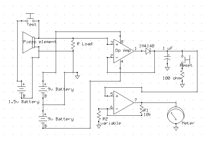
Here's the schematic diagram for the circuit that will record and briefly store the most positive voltage from the piezoelectric element.
Image
http://froglevel.org/images/SampleAndHold.jpg

The component list is:
Dual operational amplifier (op amp). Both the triangular amplifier components are packaged in a single 8-pin epoxy integrated circuit. A CA3240 op amp is preferred because it will hold the max. voltage longer, but an MC1458, LM1458, LM1558, or some others will do.
Test, Reset. Normally open, momentary contact push-button switches.
R Load. A resistor to serve as a load on the piezoelectric element. It should be <= 1 Megohm. The value can be varied to determine how much current the piezoelectic element can produce.
1N4148 diode. Nearly any silicon switching diode will serve here. The 1N4148 is a very common one.
1 uF capacitor. An unpolarized or polarized capacitor. If a polarized capacitor is used, be sure to insert it with the terminals as shown.
100 Ohm. A 100 Ohm resistor rated at least 1/4 watt.
R1. A 10 kOhm resistor rated at least 1/4 watt.
R2. A resistor of value chosen to determine how much the second op amp amplifies the piezoelectric output. The voltage registered by the meter will be amplified by (R2+R1)/R1. For example, if R1 is chosen as 1111 Ohms, the meter will register 10 times the piezoelectric peak voltage. The output can never go beyond the +/- 9v of the supply batteries.

The same circuit can be used to measure the most negative piezoelectric voltage if the 1N4148 diode is reversed. Also reverse the test battery.

I don't want to discourage you from learning about circuits. That's a very useful thing to know for many reasons, but it might be done better without the deadline for the project. I strongly urge you to be sure you define how the circuit will help to get you a good assessment of your project.

Re: piezoelectric harvesting

Posted: Tue Sep 27, 2011 5:30 pm
by quickyj
Mr. Wiggins, Thank you so much for taking the time to give me such a complete answer. I understand what are you are saying about the complexity of the whole subject. I'm not sure I can complete this project in the amount of time I was given, but you have peaked my interest in making this so I might give it a try in my spare time. Thanks again for your help. I sincerely appreciate it.

Re: piezoelectric harvesting

Posted: Tue Sep 27, 2011 5:55 pm
by deleted-71882
Okay. If you decide to try circuit building, please get in touch, and I'll be happy to help as I can.

Good luck.