Abstract
Have you ever wondered how an AM radio station works? In this project you will learn the basics of how your favorite songs are transmitted by a radio station, by building your own simple AM radio transmitter. You will learn the basics of how a transmitter works, and how you are able to tune to your favorite station and listen to music.Summary
Written by Niraj Subba, ![]()
Edited by Andrew Olson, PhD, and Ben Finio, PhD, Science Buddies
Sources
- Field, S.Q., 2006. Building a Very Simple AM Voice Transmitter, Science Toys You Can Make with Your Kids. Retrieved April 10, 2006.
Objective
The goal of this project is to build a simple AM radio transmitter and to test its broadcast range with a radio receiver.
Introduction
Electromagnetic radiation is all around us. For example, light is electromagnetic radiation and so are x-rays. When you listen to an AM or FM radio station, the sound that you hear is transmitted to your radio by the station using electromagnetic radiation as a carrier—radio waves. Electromagnetic radiation is a propagating wave in space with electric and magnetic components. In a vacuum, electromagnetic waves travel at the speed of light.
Electromagnetic waves such as light, x-rays, and radio waves are classified by their frequency or wavelength. For example, electromagnetic radiation at frequencies between about 430 terahertz (THz) and 750 THz can be detected by the human eye and are perceived as light. Electromagnetic radiation at frequencies ranging from 3 hertz (Hz) to 300 gigahertz (GHz) are classified as radio waves. Radio waves are divided into many sub-classifications based on frequency. AM radio signals are carried by medium frequency (MF) radio waves (530 to 1710 kilohertz (kHz) in North America, 530 to 1610 kHz elsewhere), and FM radio signals are carried by very high frequency (VHF) radio waves (88 to 108 megahertz (MHz)).
So how does a radio wave carry sounds such as voice or music to your radio receiver? The radio station broadcasts a carrier wave at the station's assigned frequency. The carrier wave is modulated (varied) in direct proportion to the signal (e.g., voice or music) that is to be transmitted. The modulation can change either the amplitude or the frequency of the carrier wave. The "AM" in AM radio stands for "amplitude modulation," and the "FM" in FM radio stands for "frequency modulation." A radio receiver removes the carrier wave and restores the original signal (the voice or music). Figure 1 shows graphically how amplitude modulation works.
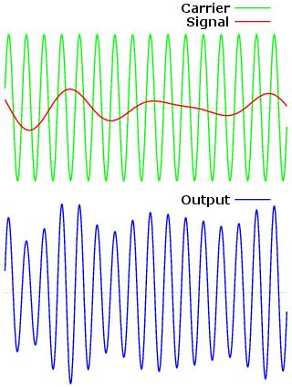
Two example graphs show the relationship between broadcast signals, carrier waves and output signals. Radiowaves are broadcasted using carrier waves of uniform wavelength and amplitude. Information is sent over these carrier waves by modifying the carrier waves with broadcast signals. The top diagram pictured shows carrier waves in green and a signal in red. In the case of AM radiowaves the signal interferes with the carrier waves amplitude creating an output signal shown at the bottom of the diagram in blue.
Figure 1. Illustration of amplitude modulation of a carrier wave by a signal. The top diagram shows a carrier wave at a set frequency and amplitude (green) and a signal to be broadcast (red). The signal is used to modulate the amplitude of the carrier wave. The bottom diagram shows the resulting output signal (blue). Note how the peaks of the output trace (its envelope) follow the form of the input signal. (Wikipedia contributors, 2006a)
In this project, you will make a simple low-power broadcast circuit, using a crystal oscillator integrated circuit and an audio transformer. You can connect the circuit to the headphone jack of a portable music player (e.g. mp3, CD or cassette tape player). You'll see that you can receive the signal through the air with an AM radio receiver. Although the circuits used in radio stations for AM broadcasting are far more complicated, this nevertheless gives a basic idea of the concept behind a broadcast transmitter. Plus it is a lot of fun when you actually have it working!
Before we get into the step-by-step instructions for building the circuit, we'll first go over the circuit design. Figure 2 shows the connections you need to make to build the circuit. The transformer isolates the music player from the rest of the circuit, couples the music player and the crystal oscillator, and "steps up" the signal voltage from the music player in proportion to the ratio of 1 kΩ to 8 Ω. The stepped up signal from the secondary coil of the transformer modulates the power to the oscillator chip (+ power at pin 14 and - power at pin 7). A wire connected to the oscillator output (pin 8) serves as the antenna for broadcasting the amplitude-modulated radio wave.
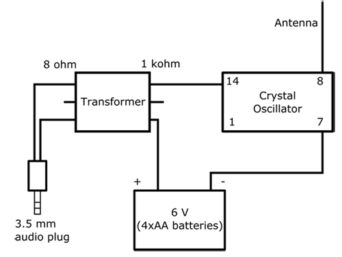 Image Credit: Ben Finio, Science Buddies / Science Buddies
The AM transmitter circuit diagram has a crystal oscillator that connects to an antenna on the 8-pin side, the negative terminal of a battery pack on the 7-pin side and a 1k ohm resistor on the 14-pin side. The 1k ohm resistor connects to the transformer and passes through to a 8 ohm resistor that connects to one lead of a 3.5mm audio jack. The other end lead of the audio jack connects back to the transformer and then connects to the positive terminal of the battery pack. Finally the battery pack contains 4 double A batteries with a total of 6 volts.
Figure 2. Simple AM transmitter circuit diagram. Note: the pins of the crystal oscillator are numbered according to standard positions for a 14-pin integrated circuit.
To do this project, you will need to know how to use a solderless breadboard. If you have never used a breadboard before you may want to take a look at the Science Buddies reference How to Use a Breadboard for Electronics and Circuits before you start this science project.
Terms and Concepts
To do this project, you should do research that enables you to understand the following terms and concepts:
- Electromagnetic radiation and waves
- Electromagnetic spectrum
- Wave model
- Speed of light
- Wavelength
- Frequency
- Amplitude
- Crystal oscillator
- Transformer
- Amplitude modulation
- Heterodyne
Bibliography
- Science Buddies Staff. (n.d.). How to Use a Breadboard. Retrieved September 25, 2015.
Another electromagnetic site:
- NASA Science. (n.d.). Introduction to the Electromagnetic Spectrum. Retrieved March 20, 2018.
Amplitude modulation:
- This webpage has an applet that lets you play with carrier and modulating signal to produce AM waves:
Nyack, C.A. (1996). Amplitude Modulation. Retrieved April 10, 2006. - Wikipedia Contributors. (2006). Amplitude Modulation. Wikipedia: The Free Encyclopedia. Retrieved April 10, 2006.
Information on crystal oscillators:
- Wikipedia Contributors. (2006). Crystal Oscillator. Wikipedia: The Free Encyclopedia. Retrieved April 10, 2006.
Information on AM (medium wave) radio:
- Wikipedia Contributors. (2007). Medium wave. Wikipedia: The Free Encyclopedia. Retrieved January 24, 2007.
Materials and Equipment
To do this experiment you will need the following materials and equipment. Most of the electronic components are available from Jameco Electronics.
- Music-playing device with a 3.5 mm audio output jack like a smartphone, mp3 player, or computer
- An AM radio for listening to your broadcasted signal
- Solderless breadboard, part #20601
- 4xAA battery holder, part #216152
- AA batteries (4), part #198707
- 1 MHz "full can" crystal oscillator, part #27861
- Optional: a second oscillator in the AM broadcast band (0.53 to 1.71 MHz in North America, 0.53 to 1.61 MHz elsewhere). Currently Jameco does not stock a second oscillator in this band, but you can purchase a 1.2288 MHz oscillator from Mouser Electronics
- 1000 Ω to 8 Ω audio transformer, Mouser Electronics part #42TU013-RC
- Jumper wire kit, part #2127718
- 3.5 mm stereo cable, part #228494
- Wire strippers (recommended, although if necessary you can use scissors or a sharp knife), multiple options available
Disclaimer: Science Buddies participates in affiliate programs with Home Science Tools, Amazon.com, Carolina Biological, and Jameco Electronics. Proceeds from the affiliate programs help support Science Buddies, a 501(c)(3) public charity, and keep our resources free for everyone. Our top priority is student learning. If you have any comments (positive or negative) related to purchases you've made for science projects from recommendations on our site, please let us know. Write to us at scibuddy@sciencebuddies.org.
Experimental Procedure
Building the Circuit
Now let's build the circuit! If you do not know how to use a solderless breadboard, see the Science Buddies reference How to Use a Breadboard for Electronics and Circuits before you start.
-
Connect the transformer, crystal oscillator, and jumper wires to the breadboard as shown in Figure 3.
- The transformer has 6 pins. Orient the transformer so the side with a "P" printed on it is facing to the right. Then insert the six pins into holes E5, E7, E9, F5, F7, and F9 as shown in Figure 3.
- The crystal oscillator has 4 pins. Orient the oscillator so the writing is facing to the left. Then insert the pins into holes E16, E22, F16, and F22, as shown in Figure 3.
- Use a jumper wire to connect hole J5 to the left-side power bus (the bus next to the red line). Note: you do not have to use a red jumper wire, you can use any jumper wire from your kit that is a convenient length. This applies to the rest of the jumper wires as well.
- Use a jumper wire to connect hole J9 to hole J16.
- Use a jumper wire to connect hole A22 to the left-side ground bus.
- Insert one end of a long jumper wire into hole F22, and leave the other end unconnected. This forms the antenna for your transmitter.
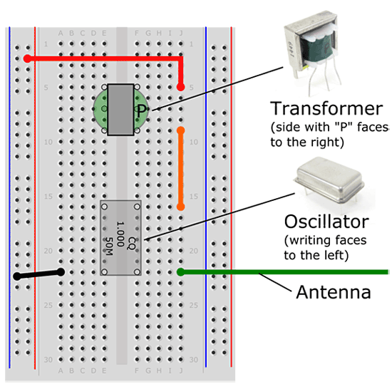 Image Credit: Ben Finio, Science Buddies / Science Buddies
Figure 3. Breadboard diagram for connecting the transformer, crystal oscillator, and jumper wires.
- Use your wire strippers to cut the 3.5 mm audio cable in half. It has three wires inside: left and right audio (with red and white insulation), and ground (uninsulated).
- Strip about 5 mm of insulation off the ends of the left and right audio wires.
- Tightly twist the strands of each individual wire together to form a bundle. This will make them stiffer and easier to push into the breadboard. If you have a soldering iron, you can tin the wires, which will also make them stiffer.
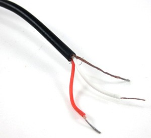 Image Credit: Ben Finio, Science Buddies / Science Buddies
Figure 4. 3.5 mm audio cable with cut and stripped ends.
-
Connect the 3.5 mm audio cable and the 4xAA battery holder to the breadboard, as shown in Figure 5.
- Plug the 3.5 mm cable's ground (uninsulated) wire into hole A9.
- Plug either the left or right audio wire (it does not matter which) into hole A5.
- Connect the battery pack's red wire to the left-side power bus.
- Connect the battery pack's black wire to the left-side ground bus.
- The breadboard of your completed circuit should look like the one in Figure 6 (remember that your jumper wires do not have to be the same color).
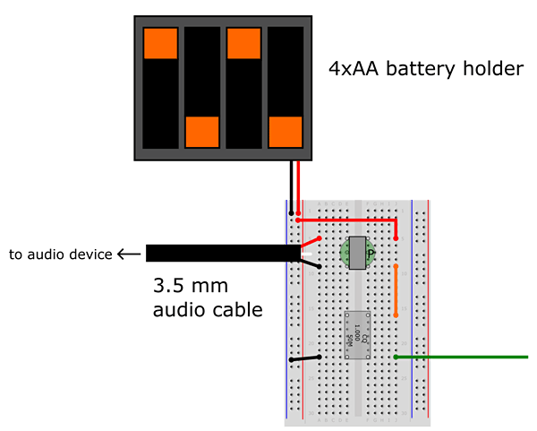 Image Credit: Ben Finio, Science Buddies / Science Buddies
Figure 5. Breadboard diagram of the battery holder and 3.5 mm audio cable connected to the breadboard.
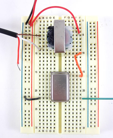 Image Credit: Ben Finio, Science Buddies / Science Buddies
Figure 6. Photograph of the completed circuit on a breadboard. Note that in this picture, the ground and audio wires are switched between holes A5 and A9, but the circuit will still work this way.
- Plug the 3.5 mm cable into the output (headphone) jack of your audio-playing device. Your completed circuit should look like the one in Figure 7.
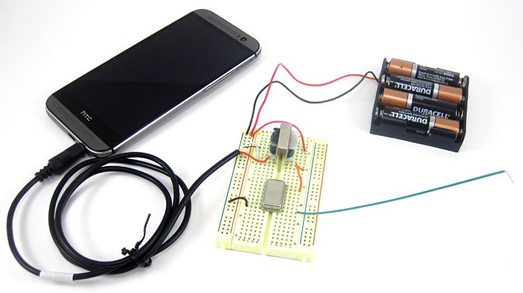
Figure 7. The completed AM radio transmitter circuit with a smartphone as a music source.
Experimenting with the Circuit
Now that you have built the circuit, here is the fun part—experimenting with it!
- Start playing music on your audio device and tune your AM radio to 1 MHz. Bring the transmitter antenna within an inch of your radio antenna (note: some radios might have a separate AM antenna inside the radio, separate from the FM antenna visible on the outside of the radio. Check your radio's instruction manual to find out). Can you hear the music that you are playing on the radio?
- Adjust the volume control of your audio device, is there any change in the quality of the sound you hear in your radio?
- Now tune your AM radio to a different frequency, say 700 kHz. Can you still hear your music?
- Tune your radio back to 1 MHz where you can hear your music. Optionally, if you purchased a second oscillator, remove the 1 MHz crystal oscillator and in its place put the 1.2288 MHz oscillator. Can you still hear your music?
- Without changing the oscillator back to 1 MHz, instead tune your radio now to 1.23 MHz. Can you hear your music?
- Until now you have kept your antenna within an inch of your radio antenna, now move your transmitter's antenna further away slowly and hear what happens. Does the quality of your sound improves or gets worse? Why?
- Rotate the radio receiver antenna relative to your transmitter's antenna (or vice versa). Does this affect the quality of the sound? Why?
- Try using a longer wire for the antenna. Does this affect the quality of the sound? Does this affect the broadcast range for your transmitter? Why?
Ask an Expert
Global Connections
The United Nations Sustainable Development Goals (UNSDGs) are a blueprint to achieve a better and more sustainable future for all.

Variations
- Try receiving the signal from your AM transmitter with a crystal radio that you build yourself. You can explore how the relative placement of the receiving and transmitting antennas affects signal strength at the receiver. To see how to build a crystal radio receiver, see the Science Buddies project Build Your Own Crystal Radio.
- Try using a 9 V transistor radio battery instead of 4 AA batteries. What differences do you notice in the signal?
- Advanced. If you have access to oscilloscope in school, try to see the signals coming out from the antenna with your music device turned OFF and then ON. Also connect the +6V of the battery directly to the oscillator bypassing the transformer and look at the signal. What difference or similarities do you see between these three signals?
- Advanced. This is an extremely rudimentary transmitter and therefore the sound quality is not going to be good. However, you could add more blocks to the present circuit and make improvements. What could you possibly add to the present circuit so that you are able move your antenna further away from your radio and still hear the music? For a slightly more complex circuit, try the following link: Bowden, B., 2006. "Micro Power AM Broadcast Transmitter," Bowden's Hobby Circuits, retrieved August 1, 2011 from http://www.bowdenshobbycircuits.info/page6.htm#amtrans.gif. How does this circuit compare to the simpler one in the project? How does the broadcast range compare? Can you relate the difference in performance to the difference in the circuits?
Careers
If you like this project, you might enjoy exploring these related careers:


Related Links
- Science Fair Project Guide
- Other Ideas Like This
- Electricity & Electronics Project Ideas
- My Favorites


