Abstract
A simple circuit and a servo motor are all you need to turn any work of art into an interactive moving creation that is happy to see you. Light sensors see your shadow as you walk past your artwork and make a servo motor move back and forth. Waving arms? Turning heads? It is all up to you!Summary
- Elmer's is a registered trademark of Elmer's Products, Inc.
- Crayola and Model Magic are registered trademarks of Crayola, Inc.
Objective
Change still piece of art into one that moves when triggered light and shadows.
Introduction
Whether you are drawing, taking photographs, crafting, or sculpting out of clay or other materials, simply put: art is fun! After you make a sculpture, where does it go? In your family's living room? On a special display shelf?
You and your family and friends probably enjoy looking at it, but it just sits there. What if it could look back at you? Or wave to you? With just a few electronic parts and a servo motor, your sculpture can come to life as you walk by.
The secret to making your creation come alive is adding a motor. You have probably seen radio-controlled cars or airplanes that steer with servo motors. With radio control, the radios determine the movement based on how you manipulate the joysticks. Robots use servo motors, too, with computers controlling how they move. You can learn more about servos by reading the Science Buddies resource Introduction to Servo Motors. They are amazing and incredibly versatile. And as you will discover doing this project, very easy to use without any radios or computers.
Making your sculptures watch you as you walk past them will involve an electronic chip that was invented back in 1970. The 555 timer chip is one of those old technologies that is just too good to stop using. We use computers for all kinds of clocks and timers now, but we did not have cheap little computers back in 1970. Back then, a timer was a circuit made of a lot of parts. An engineer came up with the 555 chip as a way of simplifying timer circuits and making them easier and more powerful. For this project, you will use one to generate the signals needed to control a servo motor.
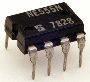 Image Credit: Wikipedia user Stefan506 / Creative Commons Attribution-Share Alike License
Figure 1. A close-up view of the 555 timer chip.
Two photoresistors work as light sensors for this project. They change their electrical properties as light or shadows fall on them. With two of them in the circuit, you can tell the timer to change how it works as light shines on, or is blocked from the sensors, and that makes the servo turn back and forth as people walk past.
Terms and Concepts
- Servo motor
- 555 timer chip
- Photoresistor
- Schematic
Questions
- What are servo motors used for?
- In the circuit for this project, what is the relationship between what the photoresistors detect and the movement of the motor?
Bibliography
- Wikipedia Contributors. (2015, July 5). 555 Timer IC. Retrieved July 5, 2015.
- 555 Timer Circuits Staff. (n.d.). SERVO TESTER Circuit. Retrieved July 5, 2015.
- Williamson Labs. (n.d.). Signetics 555 datasheet. Retrieved July 5, 2015.
- Science Buddies. (n.d.). How to Use a Breadboard. Retrieved September 5, 2015.
Materials and Equipment
Parts for the servo motor control circuit:
- 0.022uF capacitor
- 1N4148 diode
- Servo
- 3.3M resistor*
- 2.2K resistor*
- 10-100K photo resistor (2)
- 110K resistor*
- 555 8-pin DIP
- Breadboard
- 4xAA battery holder
- AA batteries (4)
- Jumper wires. There are a variety of jumper wire kits available from Jameco. Read this part of our breadboard tutorial to learn about the different types of jumper wires and decide what type is best for you.
- The parts above will allow you to build a circuit directly on a breadboard. However, you might want to connect some parts of the circuit to an art project (like a statue that you build) that is separate from the breadboard. To do this, you will need longer wires to run electrical connections from your breadboard to your statue. There are two options:
- Purchase male-to-female jumper wires. These can be used like mini "extension cords" to connect circuit components to the breadboard from a distance. However, their electrical connections might not be as reliable if they get bumped, pulled, or moved around.
- If you have a soldering iron and wire strippers available, purchase stranded hookup wire. This is flexible wire that you can cut to whatever length you need. You can solder one end to an electronic component's lead (for example, a photoresistor) and the other end to a jumper wire that you can push into the breadboard.
Craft supplies:
This will depend on what your art project will be. Here are some suggested materials. You may already have some of these around your house, or you can get them easily at a local craft store.
- Pipe cleaners or fuzzy sticks
- Craft sticks (wooden or foam)
- Construction paper or cardboard
- Foam board
- White glue
- Double-sided foam tape
- Beads
- Googly eyes or other embellishments
- Glitter
- Acrylic, tempera, or other water-cleanup paint
- Paint brushes
- Felt-tip markers
- Scissors
- Craft knife
Other optional tools:
- Needle-nose pliers (some people like them for inserting parts in breadboards)
Disclaimer: Science Buddies participates in affiliate programs with Home Science Tools, Amazon.com, Carolina Biological, and Jameco Electronics. Proceeds from the affiliate programs help support Science Buddies, a 501(c)(3) public charity, and keep our resources free for everyone. Our top priority is student learning. If you have any comments (positive or negative) related to purchases you've made for science projects from recommendations on our site, please let us know. Write to us at scibuddy@sciencebuddies.org.
Experimental Procedure
Wiring the Circuit
Regardless of what your art project looks like, the circuit to control the servo motor will be the same. So we will start with that. Figure 2 shows the circuit you will be building. It is a variation of a very common circuit that engineers design with the 555 chip. This drawing is called a schematic and it is a lot like a road map of your circuit. Wires run wherever there is a line in the schematic, and wires connect where there is a large dot at an intersection. Do not worry about understanding how to build the circuit by just looking at the drawing; we will give you step-by-step instructions.
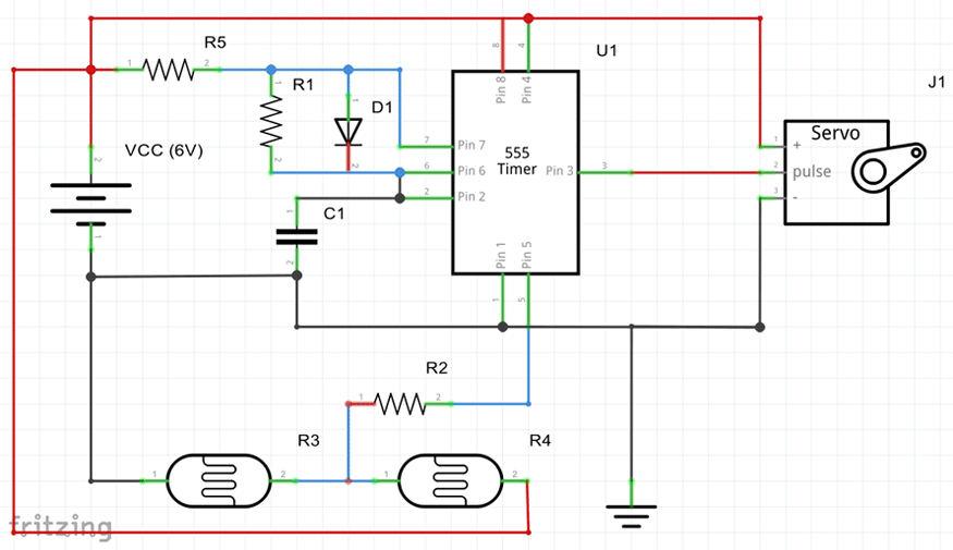 Image Credit: Howard Eglowstein, Science Buddies / Science Buddies
Figure 2. The schematic for how to wire the servo motors and photoresistors in order to get your art moving.
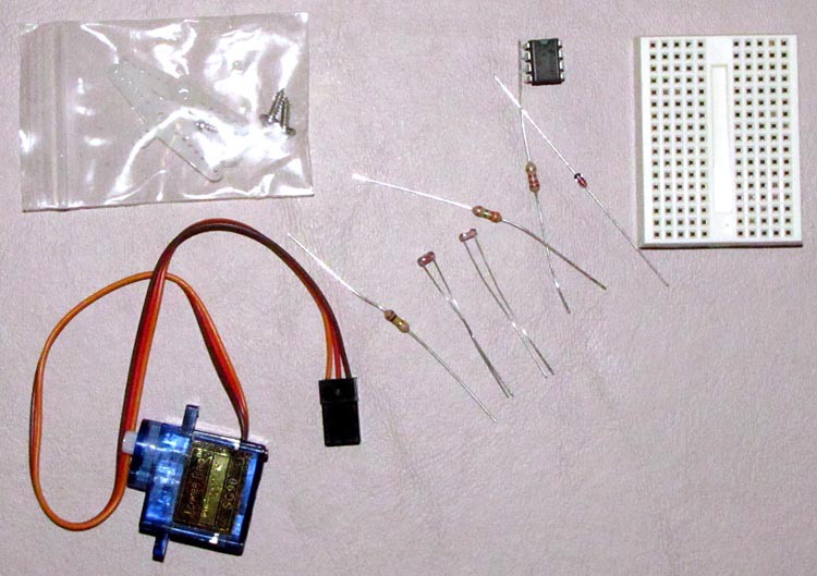 Image Credit: Howard Eglowstein, Science Buddies / Science Buddies
Figure 3. Some of the parts you will be using. From left to right, the servo motor and plastic servo horn, resistor, two photoresistors (light sensors), two resistors, diode, 555 timer chip, and breadboard.
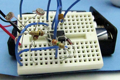 Image Credit: Howard Eglowstein, Science Buddies / Science Buddies
Figure 4. A completed circuit. This circuit is built on a "mini" breadboard, smaller than the one linked in the materials list.
Note: These instructions will assume you purchased the parts from Jameco Electronics listed in the materials section, and can assemble your circuit exactly as shown in Figure 5. If you have other parts (for example, a different breadboard, or a servo motor with different colored wires), you might not be able to follow these directions exactly. Someone familiar with electronics might be able to help you with your circuit. However, the package of jumper wires you have might have all sorts of different lengths and colors. The colors do not make any difference to the circuit, so you can choose to use colors that make sense to you. For example, using a red wire for positive battery connections and black ones for negative will help you remember which is which. You can also choose wires just for their lengths (keeping them shorter for convenience).
- Look at your breadboard. Hold it so that the valley in the middle goes up and down. On each side of the valley there are a series of rows that have five holes each. Each of the holes in each one of the rows is connected together, so putting wires in that row is like twisting them all together. You can learn more about breadboards and how they work by looking at the Science Buddies reference How to Use a Breadboard for Electronics and Circuits.
- Start with the 555 timer chip. Look at the top of the chip (pins pointing away from you). Do you see the small indentation at one end, or a small dot in one corner?
- If your chip has the indentation, hold it so that the indentation is up. The upper left corner is called pin 1. Counting down the left side will be pins 1, 2, 3, and 4. Go back up the right side, starting with the lower right corner. The pins on that side (counting from the bottom) are 5, 6, 7, and 8. Pin 1 is opposite 8, 2 is opposite 7, 3 is opposite 6, and 4 is opposite 5. Knowing which pin is which is critical to making your circuit work.
- If your chip has a single embossed dot instead of an indentation, that dot is pin 1. Proceed with the pin numbering as is explained in step 2.a.
- Plug the chip into the breadboard so the pins straddle the gap in the middle, with pins 1 and 8 in row 10, and pins 4 and 5 in row 13. If it does not immediately plug into the board, gently squeeze the pins closer and try again.
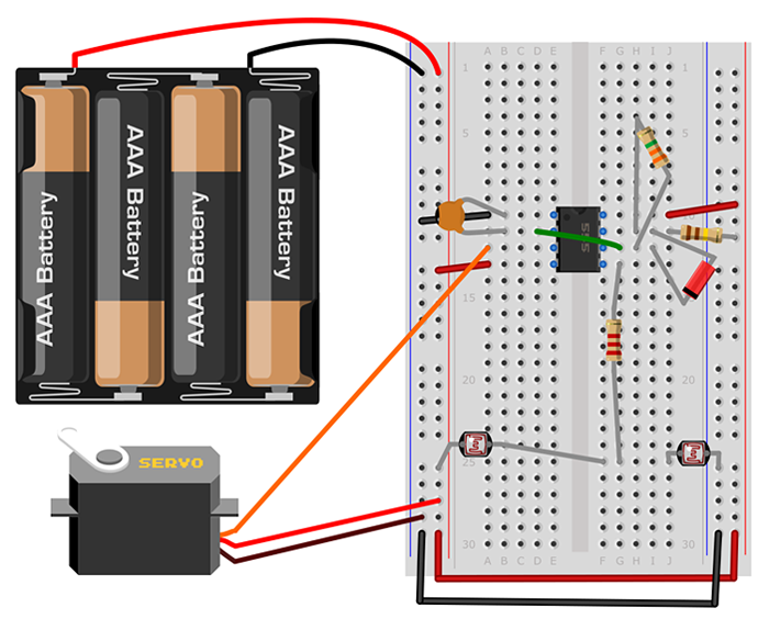 Image Credit: Howard Eglowstein, Science Buddies / Science Buddies
Figure 5. Breadboard diagram of how to build the circuit for this interactive art project. Other ways are possible, but you can follow this diagram exactly if you would like. The colors of your jumper wires do not need to match the colors shown in the diagram exactly. However, the colors for the battery pack and servo motor wires mean specific things, so those do matter.
- Connect your battery pack to the breadboard's buses (the long strips marked by the red and blue lines), but do not put the batteries in the battery pack yet. Connect the red wire to the power bus (red line) and the black wire to the ground bus (blue line).
- Use a jumper wire to connect the left-side power bus to the right-side power bus.
- Use a jumper wire to connect the left-side ground bus to the right-side ground bus.
- Use a jumper wire to connect pin 1 of the 555 chip (row 10, left side) to the ground bus.
- The capacitor (marked as C1 Figure 2) is a 0.022 μF capacitor, which may be marked as '223'. Connect one lead of the capacitor (C1) to pin 1 of the 555 chip (row 10, left side), and the other lead in a hole for pin 2 of the chip (row 11, left side). It does not matter which lead goes in which hole.
- Now you will connect the servo motor. If you purchased the servo from Jameco Electronics, the wires should be brown, red, and orange. Brown is the ground wire, red is the power wire, and the remaining orange wire is the signal that controls the servo. Note that other servo motors may have black (ground), red (power), and white (signal) wires instead. The wires have female pins at the end of them, so you can push male jumper wires into them and connect those to the breadboard.
- Connect brown lead of the servo to the ground bus.
- Connect the orange lead of the servo to pin 3 of the chip (row 12, left side).
- Connect the red lead to the power bus.
- Connect chip pin 4 (row 13, left side) to the power bus (red line).
- With resistors, it does not matter which end is which. R2 in this circuit is a 2.2kΩ (kilo-ohm) resistor marked with three stripes, red-red-red. Connect one side of R2 to chip pin 5 (row 13, right side) and connect the other end to an empty, unused row (row 25 in Figure 5).
- Tip: The next two steps will be installing the photoresistor light sensors. In your project, you may want to position the two sensors away from the breadboard, perhaps in a stand where you will place your sculpture. The materials section of the project describes the additional materials you will need to connect the light sensors off the breadboard. You may want to put them directly on the breadboard at first, while you test your circuit, then move them later.
- R3 is one of the photoresistors that you are using as a light sensor. Insert one side of R3 into the new row where you just connected R2 (row 25 in Figure 5) and the other side into the ground bus.
- R4 is the other photoresistor. Insert one side of R4 into the new row where you connected R2 and R3 (row 25 in Figure 5), and the other side of R4 into the power bus.
- R1 is a 3.3MΩ resistor, marked with orange-orange-green stripes. Use R1 to connect chip pins 6 and 7 (rows 11 and 12, right side).
- D1 is a diode. Diodes work as valves to prevent electricity from flowing back and forth, so it does matter which way you use it. Find the end of D1 that has the black or gray band. Connect that end of D1 to chip pin 6 (row 12, right side).
- Connect the other end of D1 to chip pin 7 (row 11, right side).
- R5 is a 110kΩ resistor, marked as brown-brown-yellow. Note: 110kΩ is an unusual size. If you purchased a resistor kit, you might have a 100kΩ resistor brown-black-yellow) or a 120kΩ resistor (brown-red-yellow), and can use that instead. Connect one end of R5 to chip pin 7 (row 11, right side) and the other end to the power bus.
- Use a jumper wire to connect chip pin 8 (row 10, right side) to the power bus.
- Use a jumper wire to connect chip pin 2 (row 11, left side) to chip pin 6 (row 12, right side).
- That is it for wiring! Take a few minutes to check and double-check your work and make sure that your version looks like the one in Figure 5. A single misplaced wire can prevent the entire circuit from working, so be careful!
- Check to see if any of the wires or resistor/capacitor leads are touching each other. If you find any, bend them a bit to keep them separate.
- Once you think you have everything right, go ahead and put the batteries in the battery holder. The servo motor should rotate to a position and stay reasonably steady. If you see or smell smoke, immediately disconnect the battery pack and double-check your wiring, because you have a short circuit somewhere.
- With a bright light above you, use your finger to cast a shadow on the two photoresistors one at a time. As your shadow covers one of the sensors the motor will turn. Cast the shadow over the other one and it turns the other way. If your circuit is working, congratulations; it is time to do the art part of this project. If the circuit is not working, do not worry; the Troubleshooting section will help you find your problem and fix it.
Troubleshooting
You might be asking, "My circuit does not work. What did I do wrong?" Breadboards can be tricky sometimes. Try these fixes:
- Did you identify pin 1 of the chip correctly and identify the other seven pins? If you hold the chip with the pins facing away from you and the indentation or the small hole at the top, pin 1 will be at the upper left. Count down the left side to get 2, 3, and 4, then starting at the lower right, count up to see 5, 6, 7, and 8. The notch in the chip is facing toward the top of Figure 5. If you put the chip into the breadboard upside-down, the circuit will not work.
- Are your wires firmly pressed into the breadboard as far as they will go? Check each wire.
- Is the diode D1 in the right direction? The black or gray band printed on the body will go toward pin 6 of the chip, and the other end goes into pin 7. The circuit will not work if it is the wrong way.
- Do not confuse the resistors. It matters which is which, so double-check the colored stripes.
- Remember that each row of holes connects all of the holes on that side of the breadboard together, but not any other rows.
Creating Your Art
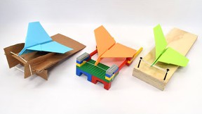
With the circuit complete, gather your art materials. Use what you enjoy to sculpt with, whether it is modeling clay, gluing foam shapes together, or making things with craft sticks. Figure 6 shows some materials you might find useful. Small servo motors cannot move very heavy objects, so do not make any part of the sculpture too big or heavy.
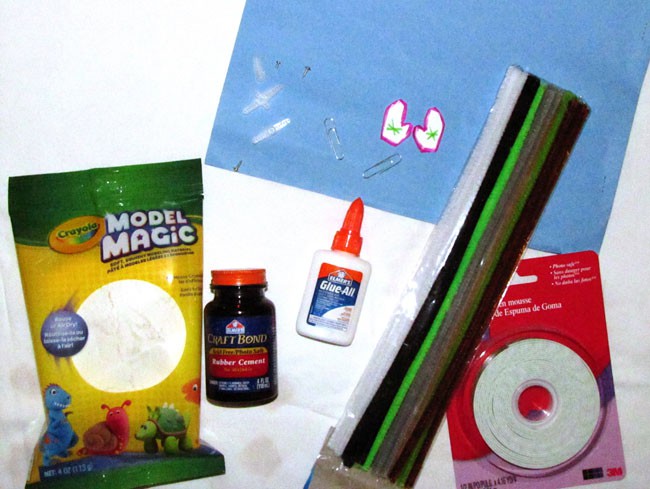 Image Credit: Howard Eglowstein, Science Buddies / Science Buddies
Figure 6. Some craft materials you might find useful. Clockwise, starting at the top, the plastic servo horn that will move your sculpture's head, arms, etcetera; paper clips, paper cutouts, pipe cleaners, double-sided foam tape, white (school) glue, rubber cement, and modeling clay. Not shown: clear or masking tape, googly eyes, staples and a stapler, glitter, paint, markers.
- The servo motor itself will need to be stuck into or attached to something. Figure 7 shows the servo stuck into the body of a snowman made of modeling material. The pipe cleaner arms are attached to the servo horn by wrapping them around it, as shown in Figure 7. The snowman's mittens are simply taped on with regular clear tape. Let your imagination take over; what will your sculpture look like? What will you create? Aliens? Monsters? Flowers that sway back and forth?
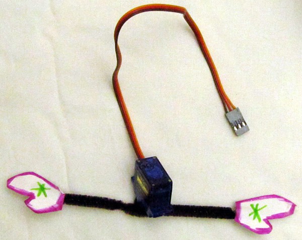 Image Credit: Howard Eglowstein, Science Buddies / Science Buddies
Figure 7. The pipe cleaner and snowman hands attached to the servo horn and placed on the servo. Attach the hands so that they will be visible from the front.
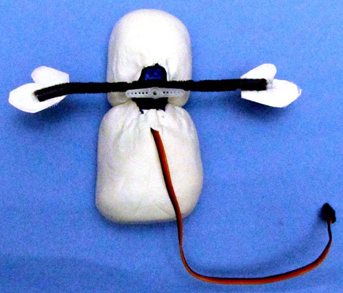 Image Credit: Howard Eglowstein, Science Buddies / Science Buddies
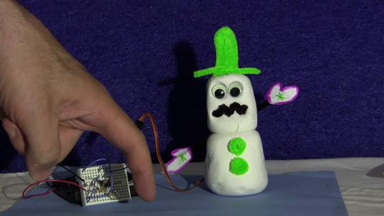
Figure 8. The whole servo motor and circuit need to be attached to the artwork.
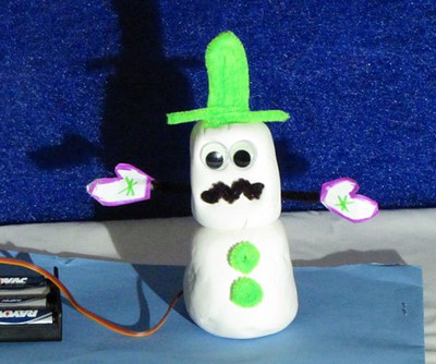
Arrange your sculpture like we did in Figure 9 so that the servo motor is hidden (a magician never reveals his or her secrets!) and the light sensors are facing forward. Point a light source at the sensors and wait until someone walks by. As their shadow crosses one sensor, the servo motor will move one way, then the other, as the shadow continues over the other sensor. Our snowman waves a cheery greeting. What will your sculpture do?

Figure 9. A snowman that waves a happy greeting as you walk by!
Ask an Expert
Global Connections
The United Nations Sustainable Development Goals (UNSDGs) are a blueprint to achieve a better and more sustainable future for all.

Variations
- If you stick the servo motor into a body so that the rotating shaft points up, and attach the servo horn to a head, your sculpture can turn its head back and forth to follow you as you walk by.
- The light sensors might not be easy to position in a good spot if they are stuck into the breadboard. You can use wire to extend the leads of the photoresistor light sensors a reasonable distance (perhaps 25 or 30 cm). Solder or twist a wire onto each of the wires on the two sensors and plug those into your breadboard. You can position the sensors farther apart and hide the breadboard. See the materials list for more suggestions on how you can do this if you do not have a soldering iron.
Careers
If you like this project, you might enjoy exploring these related careers:


Related Links
- Science Fair Project Guide
- Other Ideas Like This
- Robotics Project Ideas
- Technology of Art Project Ideas
- My Favorites