Keep Your Arduino Robot From Falling Off a Cliff
Abstract
Humans cannot see infrared light, but robots can! At least, they can when they use special infrared light sensors. These sensors can help robots detect nearby objects to avoid collisions and even help them avoid driving off edges. In this project you will build your own Arduino robot that uses infrared sensors to avoid driving off the edge of a table.Summary
Objective
Build and program a robot that can use infrared sensors to avoid driving off the edge of a table.
Introduction
Advanced autonomous robots like the Perseverance rover (Figure 1) use a variety of cameras to navigate and assess the size and shape of obstacles. For example, determining how big a rock is will let the robot decide whether to just drive over the rock, or drive around it. The cameras can also help the robot plan out a path and avoid driving into a hole or crater.
 Image Credit: Wikimedia, NASA / Public domain
Figure 1. The Perseverance rover.
Simpler robots, like iRobot's Roomba®, an autonomous vacuum cleaner robot (Figure 2), typically do not use cameras. However, they still use a variety of simpler, cheaper sensors to help navigate. Early versions of the Roomba used a bump sensor to physically detect when the robot bumped into something like a piece of furniture. Newer, faster-moving versions use forward-facing infrared (IR) sensors. These sensors emit IR light that is bounced back when the robot gets close to an object. This helps the robot know to slow down before it crashes. Downward-facing IR sensors can also be used to detect a "cliff," like the top of a set of stairs (a single step might not seem like a "cliff" to a human, but it does to a tiny robot!). Normally, the downward-facing sensors are very close to the floor, so the IR light is bounced back. When a sensor goes over the edge of the stairs, suddenly there is a lot of empty space beneath it, and the light is not bounced back. This helps the robot know to turn around before it accidentally drives down the stairs.
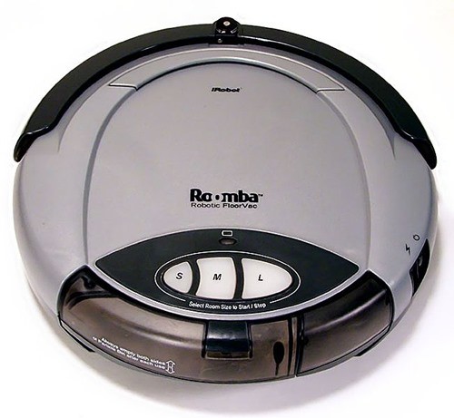 Image Credit: Wikimedia user Larry D. Moore / Creative Commons Attribution Share-Alike 3.0 Unported
Figure 2. A Roomba® robotic vacuum cleaner. (Source: Larry D. Moore, CC BY-SA 3.0, Wikimedia Commons.)
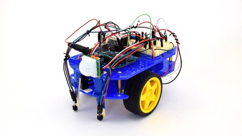
In this project, you will build a robot that behaves similar to a Roomba®. It will have two IR sensors that you can mount on the robot. Can you design a program that will allow the robot to drive around without falling off the edge of a table?
Terms and Concepts
Questions
- What are the advantages and disadvantages of using cameras vs. infrared sensors for a robot to navigate?
Bibliography
General electronics references:
- Science Buddies (n.d.). How to Use a Breadboard. Retrieved July 6, 2020.
- Science Buddies (n.d.). How to Use a Multimeter. Retrieved July 6, 2020.
- Science Buddies (n.d.). Wire Stripping Tutorial. Retrieved July 6, 2020.
References for using an Arduino:
- Science Buddies (n.d.). How to Use an Arduino. Retrieved July 6, 2020.
- Arduino (n.d.). Language Reference. Retrieved July 6, 2020.
Reference about the cameras on the Mars 2020 Perseverance rover:
- NASA (n.d.). The Cameras on the Mars 2020 Perseverance Rover. Retrieved July 10, 2020.
References about the Roomba's sensors:
- iRobot (n.d.). Why is my Roomba® Bumping into Obstacles Harder than before?. Retrieved November 21, 2023.
- Layton, J. (n.d.). How Robotic Vacuums Work. HowStuffWorks. Retrieved July 10, 2020.
Datasheet for the L293D H-bridge motor driver:
- Texas Instruments (January 2016). L293x Quadruple Half-H Drivers. Retrieved July 8, 2020.
Datasheet for the IR sensor:
- Everlight Electronics Co., Ltd. (2007, April 4). Technical Data Sheet Opto Interrupter. Retrieved October 2nd, 2019.
Reference explaining how the part of the circuit used in this project works (in a robot without an Arduino):
- Science Buddies (n.d.). Build a Zippy Line-Following Robot (Bluebot Project #2). Retrieved July 15, 2020.
Materials and Equipment 
Recommended Project Supplies
- BlueBot: 4-in-1 Robotics Kit, available from our partner Home Science Tools. The kit includes a robot chassis, wheels, motors, breadboard, batteries, and circuit parts to build four different robots.
- Science Buddies Electronics Kit for Arduino, available from our partner Home Science Tools.
- Windows or Mac computer. Unfortunately, Arduino software does not currently work well with Chromebooks. Your computer will need:
- Access to the Arduino IDE, either installed local version or web-based editor. Watch this video for a comparison of the two options.
- USB port. The Science Buddies kit comes with a USB-A to B cable. The "B" end plugs into the Arduino and the "A" end plugs into your computer. You will need an adapter or different cable if your computer only has USB-C ports. Watch this video to learn about the different types of cables and adapters.
- You will also need to gather these items, not included in the kit:
- Double-sided foam tape
- Popsicle sticks
- Recommended: piece of plywood (about 2×2 feet) that you can put on the floor. This will allow you to safely test your robot so it does not fall very far if it doesn't work.
- Some additional tools are recommended for working with circuits:
- A digital multimeter is strongly recommended for help with troubleshooting
- Alligator clip leads make it easier to connect your multimeter probes to your circuit
- Needle nose pliers or tweezers make it easier to handle small parts
- Wire strippers allow you to cut wires to custom lengths, keeping your circuit neater
- Lab notebook
Disclaimer: Science Buddies participates in affiliate programs with Home Science Tools, Amazon.com, Carolina Biological, and Jameco Electronics. Proceeds from the affiliate programs help support Science Buddies, a 501(c)(3) public charity, and keep our resources free for everyone. Our top priority is student learning. If you have any comments (positive or negative) related to purchases you've made for science projects from recommendations on our site, please let us know. Write to us at scibuddy@sciencebuddies.org.
Experimental Procedure
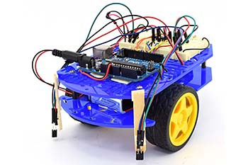
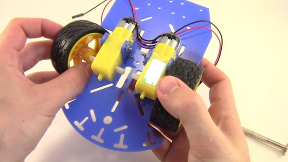
- Assemble your Bluebot chassis as shown in this video. However, instead of mounting the 4xAA battery pack on top of the robot, mount it on the lower plate. Then mount your Arduino next to the breadboard on the top plate.
- To control your robot's motors, you will use the L293D H-bridge motor driver chip, included in your Bluebot kit. This chip allows you to control the speed and direction of two motors. Figure 3 shows the pinout from the chip's datasheet and Table 1 describes the functions of the pins. When one of the input pins ("A") for a motor is high and the other one is low, the motor will spin. Reversing which pin is high/low reverses the motor's direction (Table 2). If both input pins are high or both input pins are low, the motor will stop. Do not worry if that does not make sense yet. You will wire the circuit and see example code in the next few steps.
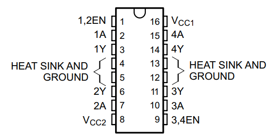 Image Credit: Ben Finio, Science Buddies / Science Buddies
Pinout for the L293D H-bridge chip. Pins are in two columns of 8, labeled one through 16, counter-clockwise from the top left, as follows: 1,2EN 1A 1Y 'HEAT SINK AND GROUND' 'HEAT SINK AND GROUND' 2Y 2A VCC2 3,4EN 3A 3Y 'HEAT SINK AND GROUND' 'HEAT SINK AND GROUND' 4Y 4A VCC1
Figure 3. L293D H-bridge chip pinout.
| Name | Pin number(s) | Description |
|---|---|---|
| VCC1 | 16 | Digital logic voltage supply (5V from Arduino) |
| VCC2 | 8 | Motor power voltage supply (6V from 4xAA battery pack) |
| GROUND | 4, 5, 12, 13 | Electrical ground |
| 1,2EN | 1 | Speed control for motor 1 using pulse width modulation (PWM) signal from Arduino |
| 3,4EN | 9 | Speed control for motor 2 using pulse width modulation (PWM) signal from Arduino |
| 1A, 2A | 2, 7 | Inputs to control motor 1 using Arduino digital pins |
| 3A, 4A | 10, 15 | Inputs to control motor 2 using Arduino digital pins |
| 1Y, 2Y | 3, 6 | Outputs to drive motor 1 |
| 3Y, 4Y | 11, 14 | Outputs to drive motor 2 |
| 1A | 2A | Motor 1 behavior |
|---|---|---|
| Low | Low | Stop |
| Low | High | Spin |
| High | Low | Spin the other way |
| High | High | Stop |
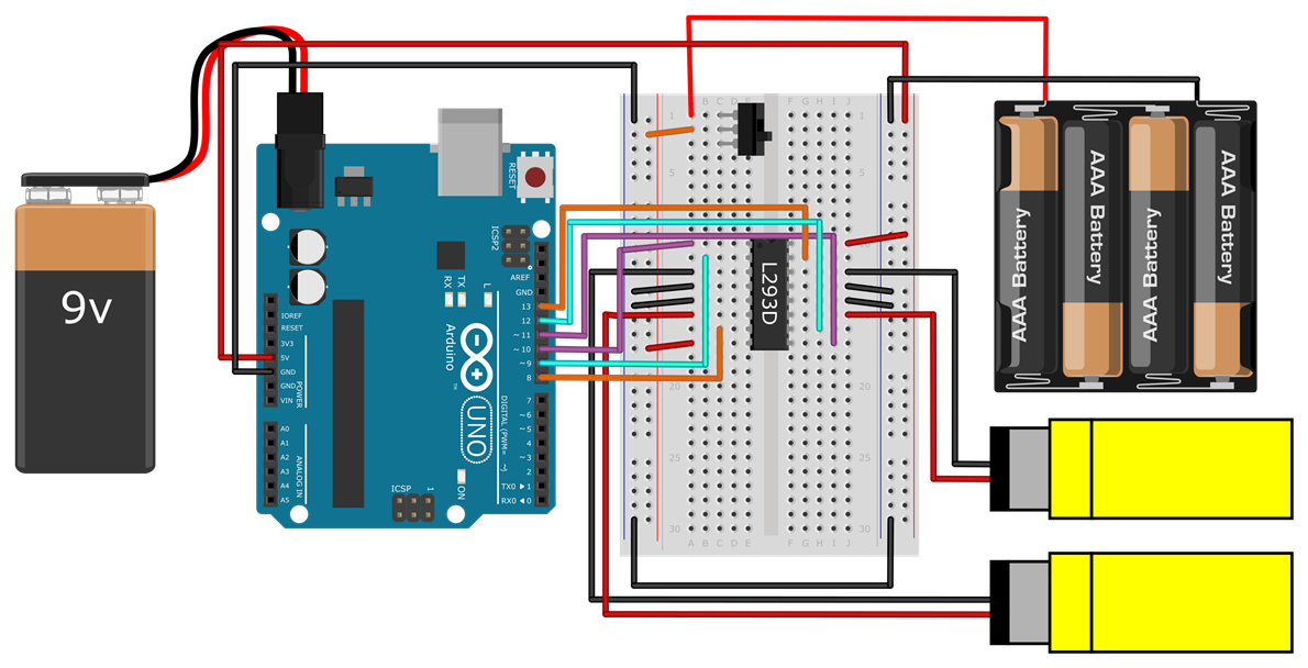
- Before you worry about connecting the bump sensors, you should make sure your robot's motors work and that it can drive around. Connect your motors, batteries, and the L293D as shown in Figure 4 (note: there is more than one correct way to wire the circuit, this is just an example). The colors shown in the picture are for readability purposes only, your wire colors do not need to match. If you are not sure how to wire a circuit on a breadboard, see the How to Use a Breadboard resource. A few things to look out for when building the circuit:
- Make sure the L293D is oriented with the notch facing "up" on the breadboard.
- Important: all the components in your circuit should have a "common ground." This means the Arduino's ground pin, the L293D's ground pins, and the 4xAA battery pack's negative wire should all be connected to the ground bus on the breadboard, and the ground buses on opposite sides of the breadboard should be connected.
- However, make sure you do not short-circuit the 5V Arduino supply to the 6V battery supply. In the diagram, notice how the left and right power buses on the breadboard are not connected with a jumper wire. The left-side bus provides 6V from the battery pack, and the right-side bus provides 5V from the Arduino. The H-bridge makes use of both power supplies: one for internal logic (5V from the Arduino) and one to power the motors (6V from the batteries). The external 4xAA battery pack is required because the Arduino cannot provide enough current to drive the motors directly.
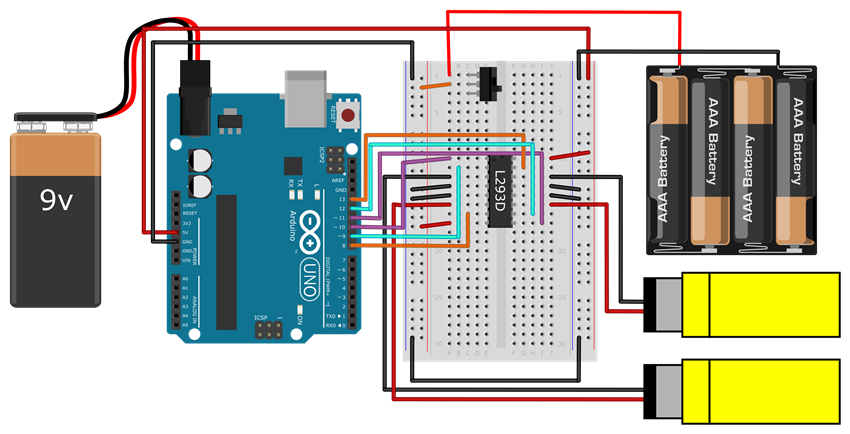 Image Credit: Ben Finio, Science Buddies / Science Buddies
Circuit diagram with the following connections: 9V battery to Arduino barrel jack; Arduino 5V pin to breadboard right-side power bus; Arduino GND pin to breadboard ground bus; 4xAA battery pack positive wire to breadboard A1; 4xAA battery pack ground wire to breadboard ground bus; Jumper wire connecting breadboard left and right ground buses; Do NOT connect the breadboard left and right power buses, this will short the Arduino 5V supply to the 6V from the battery pack; Power switch in breadboard C1, C2, C3; Jumper wire from left side power bus to A2; L293D chip straddling middle gap in breadboard from rows 10-17, with notch facing up (towards row 1); Jumper wire from breadboard A10 to Arduino pin 10; Jumper wire from breadboard B11 to Arduino pin 9; Motor negative lead to breadboard A12; Jumper wire from breadboard A13 to ground bus; Jumper wire from breadboard A14 to ground bus; Motor positive lead to breadboard A15; Jumper wire from breadboard C16 to Arduino pin 8; Jumper wire from breadboard A17 to left side power bus; Jumper wire from breadboard J10 to right side power bus; Jumper wire from breadboard G11 to Arduino pin 13; Motor negative lead to breadboard J12; Jumper wire from breadboard J13 to ground bus; Jumper wire from breadboard J14 to ground bus; Motor positive lead to breadboard J15; Jumper wire from breadboard H16 to Arduino pin 12; Jumper wire from breadboard H17 to Arduino pin 11;
Figure 4. Wiring diagram for connecting the Arduino to the L293D, your robot's motors, and batteries. A bigger version of the image is available.
- Make sure the power switch for the 4xAA battery pack is off and that the barrel jack for the 9V battery is unplugged (always do this before connecting the USB cable to program your Arduino). Enter the code shown in Figure 5 and upload it to your Arduino. If you are unsure how to do this, refer to the How to Use an Arduino guide.
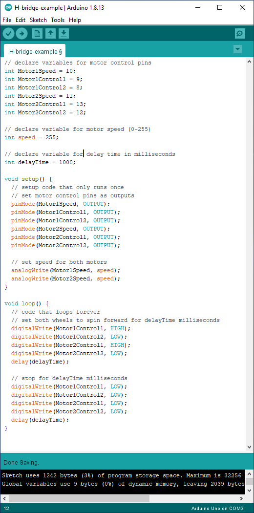 Image Credit: Ben Finio, Science Buddies / Science Buddies
// declare variables for motor control pins int Motor1Speed = 10; int Motor1Control1 = 9; int Motor1Control2 = 8; int Motor2Speed = 11; int Motor2Control1 = 13; int Motor2Control2 = 12; // declare variable for motor speed (0-255) int speed = 255; // declare variable for delay time in milliseconds int delayTime = 1000; void setup() { // setup code that only runs once // set motor control pins as outputs pinMode(Motor1Speed, OUTPUT); pinMode(Motor1Control1, OUTPUT); pinMode(Motor1Control2, OUTPUT); pinMode(Motor2Speed, OUTPUT); pinMode(Motor2Control1, OUTPUT); pinMode(Motor2Control2, OUTPUT); // set speed for both motors analogWrite(Motor1Speed, speed); analogWrite(Motor2Speed, speed); } void loop() { // code that loops forever // set both wheels to spin forward for delayTime milliseconds digitalWrite(Motor1Control1, HIGH); digitalWrite(Motor1Control2, LOW); digitalWrite(Motor2Control1, HIGH); digitalWrite(Motor2Control2, LOW); delay(delayTime); // stop for delayTime milliseconds digitalWrite(Motor1Control1, LOW); digitalWrite(Motor1Control2, LOW); digitalWrite(Motor2Control1, LOW); digitalWrite(Motor2Control2, LOW); delay(delayTime); }
Figure 5. Example code to control the robot's motors using the H-bridge.
- Put your robot on the ground and turn the power switch on. If everything is working correctly, the robot should repeatedly drive forward for one second, then pause for one second. If it does not, here are some common troubleshooting steps:
- Instead of changing your code, you can just switch the red and black wires for a motor to change the direction it spins. You can do this if your robot goes backwards or spins in circles instead of driving forward.
- If your motors do not spin at all, double-check all of your wiring. If your H-bridge is not wired properly, your motors will not spin.
- If your motors still do not spin, use a multimeter to debug your circuit. Refer to the How to Use a Multimeter guide if needed. Try the following:
- Make sure you have 5V coming from the Arduino.
- Make sure you have 6V coming from the 4xAA battery pack.
- Measure the voltages on Arduino the Arduino output pins to make sure they are what you expect (e.g. based on the code, pin 9 should toggle between 5V and 0V).
- To confirm that your motors work, disconnect them from the H-bridge and connect them directly to 6V and ground on the breadboard.
- To confirm that your H-bridge works, disconnect it from the Arduino's digital pins. Use jumper wires to manually connect the H-bridge's input pins to 5V or 0V on the breadboard. (Make sure you reconnect the motors to the H-bridge first.)
- Practice steering your robot. Can you modify the program in Figure 5 to make your robot drive in a square? This is called "open loop" navigation, or "dead reckoning." The robot is hard-coded to follow a pre-determined path, without responding to any sensor input. This type of navigation is generally not a good idea, because small errors will accumulate over time, and eventually the robot will drift off course. However, it is a good way to practice programming and make sure your circuit works.
- Now it is time to connect an IR sensor. The IR sensor has four pins. Two of the pins are connected to an IR light emitting diode (LED), which emits infrared light. The other two pins are connected to an IR phototransistor, which detects infrared light. You can read more about how the sensor works in its datasheet, which is linked in the Bibliography. Use the male-female jumper wires in your kit to connect to the sensor, as shown in Figure 6.
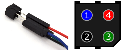 Image Credit: Ben Finio, Science Buddies / Science Buddies
Figure 6. Male-female jumper wires connected to the IR sensor's pins. You will see a small diagonal notch on one corner of the sensor. With the pins facing you and this notch in the lower right, the pins are numbered 1, 2, 3, 4 counter-clockwise starting from the upper left. Connect blue, black, green, and red wires to pins 1, 2, 3 and 4 respectively.
- Connect the IR sensor to your Arduino as shown in Figure 7. Note that the H-bridge, motors, and batteries are omitted from this diagram to avoid clutter, but you can leave them connected in your circuit.
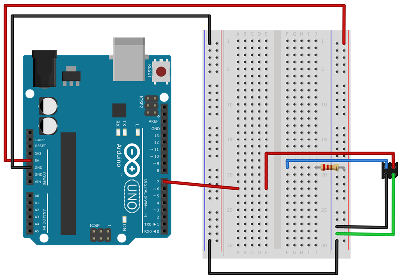 Image Credit: Ben Finio, Science Buddies / Science Buddies
Figure 7. IR sensor connected to the Arduino
- Start a new Arduino sketch and enter the code shown in Figure 8.
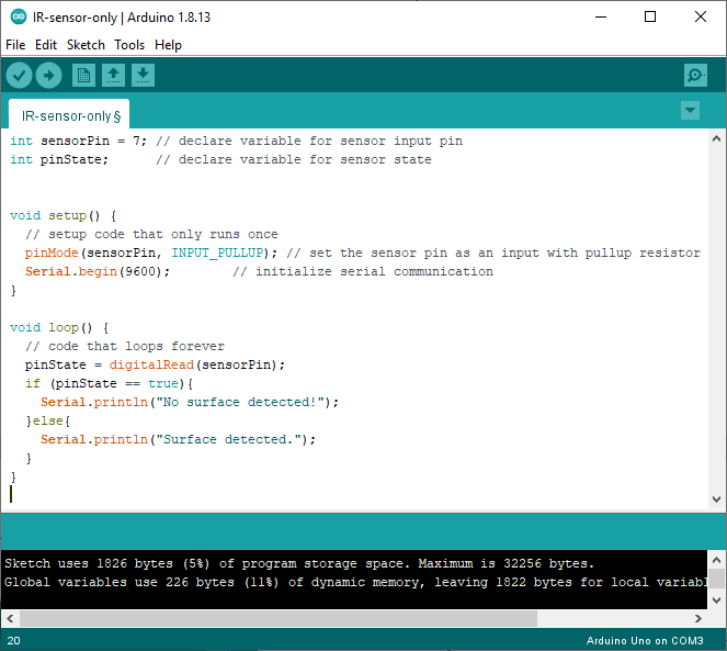 Image Credit: Ben Finio, Science Buddies / Science Buddies
int sensorPin = 7; // declare variable for sensor input pin int pinState; // declare variable for sensor state void setup() { // setup code that only runs once pinMode(sensorPin, INPUT_PULLUP); // set the sensor pin as an input with pullup resistor Serial.begin(9600); // initialize serial communication } void loop() { // code that loops forever pinState = digitalRead(sensorPin); if (pinState == true){ Serial.println('No surface detected!'); }else{ Serial.println('Surface detected.'); } }
Figure 8. Example code read the IR sensor using the Arduino's digital input.
- Upload the code to your Arduino, and leave the Arduino plugged into the USB cable. Select Tools→Serial Monitor from the top menu in your Arduino window. Make sure you select "9600 baud" from the drop-down menu in the lower right. This will give you a window that prints a message indicating whether or not the IR sensor detects a nearby surface (Figure 9). Try holding the IR sensor a few millimeters from the surface of your table or desk, then moving the IR sensor off the edge of the table so it points towards the floor. You should see the message change.
- If the message displayed in your serial monitor does not change when you move the sensor, double-check your wiring. Use a multimeter to confirm that the voltage on the Arduino's input pin changes when you move the sensor around. If it does not, your sensor is wired incorrectly.
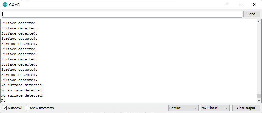 Image Credit: Ben Finio, Science Buddies / Science Buddies
Figure 9. The Arduino serial monitor displaying messages to indicate whether or not the switch is pressed.
- You now have all the pieces that you need to build an autonomous robot that will avoid driving off an edge!
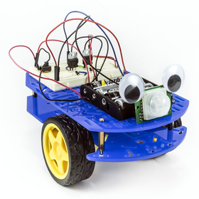
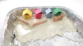
- You can use popsicle sticks and tape to mount downward-facing IR sensors on your robot (Figure 10).
- Important: try practicing your robot's behavior with a piece of plywood on the floor. You may need to prop the plywood up on some books or boxes to get enough distance for the IR sensors to detect the edge. However, this way your robot does not have very fall to far if it does not work properly. If you let your robot drive around on a full-height table or desk, make sure you are ready to catch it! Your robot will break if it falls off a table.
- Can you program your robot to navigate based on readings from one or more IR sensors? For example, try programming these different behaviors (see the next step for hints). Which behavior do you think would be best for a robot that needs to drive around to explore without risking falling off an edge?
- Put one IR sensor on the front of the robot and one sensor on the back. Make the robot change direction whenever it detects an edge.
- Put both IR sensors on the front of the robot, one on the left and one on the right. Make the robot back up and turn around whenever it detects an edge.
- Make the robot follow the edge of the table. This one is risky, but impressive when it works!
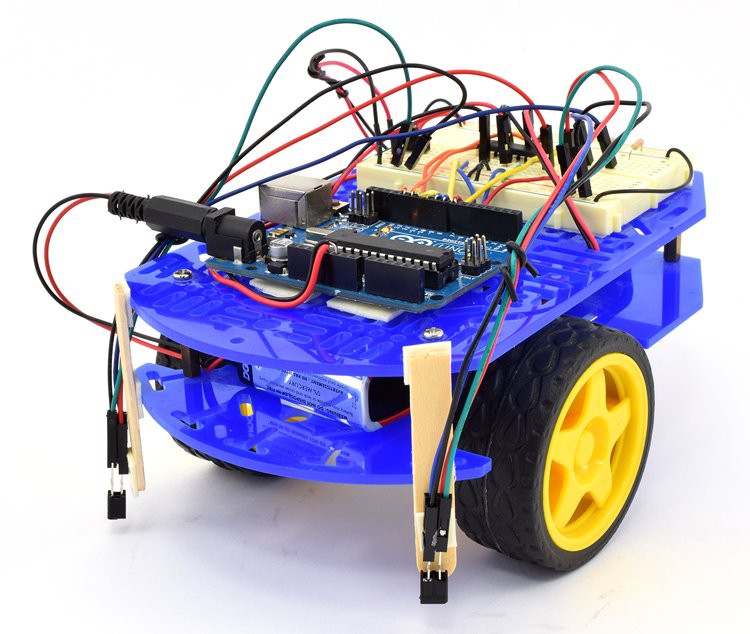 Image Credit: Ben Finio, Science Buddies / Science Buddies
Figure 10. Robot with two downward-facing IR sensors mounted on the front.
- Depending on your level of programming experience, you may need to read more in the Arduino Language Reference. You can also ask for help in the Science Buddies Ask an Expert forums. Here are some hints and suggestions:
- It is bad practice to repeatedly copy and paste the same lines or sections of code. If you find yourself doing so, it is better to put that code in a function. It may be useful to make functions for basic robot movements like "driveForward" or "turnRight." Can you simplify the code you wrote to make your robot driving in a square using functions?
- "IF/ELSE" statements allow your program to do different things depending on whether or not certain conditions are true (for example, if a variable is above or below a certain value). Can you make your robot's motion depend on the sensor input, instead of hard-coding a certain behavior?
- You can change the motors' speed using the analogWrite() command (see Figure 7). In the example program the motors are set to "full speed," or 255. It might be easier to control your robot if it is not going full speed at all times.
Ask an Expert
Global Connections
The United Nations Sustainable Development Goals (UNSDGs) are a blueprint to achieve a better and more sustainable future for all.

Variations
- Can you use the other sensors in your Bluebot kit to program other navigation behaviors for your robot? See this autonomous robot project idea for ideas.
Careers
If you like this project, you might enjoy exploring these related careers:


Contact Us
If you have purchased a kit for this project from Science Buddies, we are pleased to answer your questions.In your email, please follow these instructions:
- What is your Science Buddies kit order number?
- Please describe how you need help as thoroughly as possible:
Examples
Good Question I'm trying to do Experimental Procedure step #5, "Scrape the insulation from the wire. . ." How do I know when I've scraped enough?
Good Question I'm at Experimental Procedure step #7, "Move the magnet back and forth . . ." and the LED is not lighting up.
Bad Question I don't understand the instructions. Help!
Good Question I am purchasing my materials. Can I substitute a 1N34 diode for the 1N25 diode called for in the material list?
Bad Question Can I use a different part?
Contact Us
Related Links
- Science Fair Project Guide
- Other Ideas Like This
- Robotics Project Ideas
- Space Exploration Project Ideas
- My Favorites


