Abstract
What does it take to launch a robot to Mars or for a satellite to explore our outer solar system? In this project you will explore the physics of a rocket as you predict its performance, launch it, and measure the actual results. This is rocket science!Summary
Thanks to Tim Milligan of Apogee Components for helpful discussion about this project.
Objective
Launch a model rocket with different engines, predict its performance, and measure how high it actually goes.
Introduction
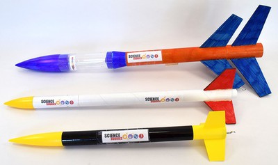
Model rockets come in a variety of shapes and sizes (Figure 1). A basic model rocket consists of the rocket's body, the nose cone, a recovery system (like a parachute), the fins, and the engine (also called the motor or propellant), along with some additional components, as shown in Figure 2. You can safely launch low-power model rockets from a field using a launch system like the one shown in Figure 3. If you are new to model rocketry, you should review the "New to Model Rocketry?" guide by Apogee Components in the Bibliography before you proceed. The rest of this introduction will explain the physics of model rocket flight and how you can take measurements of a rocket's flight for your science project.

Figure 1. Three different types of model rockets. From top to bottom: the Estes Loadstar II, the Apogee Research Express, and the Apogee Apprentice.
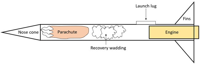 Image Credit: Ben Finio, Science Buddies / Science Buddies
cross-sectional diagram of a model rocket. The rocket's body is represented by a horizontal rectangle. The rocket's nose cone is a triangle attached to the left end of the rectangle. The parachute, recovery wadding, and engine are shown inside the body. The launch lug is a small rectangle attached to the side of the rocket. The fins are triangular pieces attached to the bottom of the rocket.
Figure 2. Cross-sectional diagram of a basic model rocket. Note: This diagram does not show every single part of the rocket. Read the instructions that come with your rocket for assembly details.
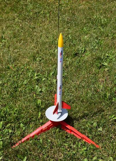 Image Credit: Ben Finio, Science Buddies / Science Buddies
Figure 3. A typical low-power model rocket launch pad.
Model rocket flight is broken up into three phases (Figure 4). During the boost phase, the rocket's engine burns propellant, which generates thrust and pushes the rocket upward. During the coast phase, the engine has burned out, but the rocket continues to fly upward due to the high velocity it achieved during the boost phase. The highest point of the rocket's flight is called the apogee. Finally, during the recovery phase, the rocket slowly falls back to the ground. The descent is typically slowed by something like a parachute or streamers, although some rockets may be designed to tumble or glide back to the ground.
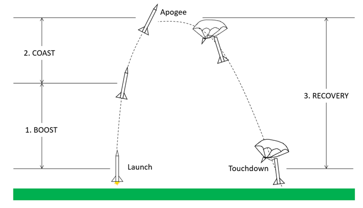 Image Credit: Ben Finio, Science Buddies / Science Buddies
Figure 4. The three phases of a model rocket's flight.
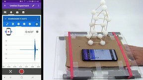
Electronic sensors can help you measure different aspects of your rocket's flight. An accelerometer is an electronic sensor that measures acceleration. An altimeter is an electronic sensor that measures the rocket's altitude by measuring barometric pressure. If your rocket has a payload bay (Figure 5), you can mount a sensor inside your rocket and it will record information about the flight. Altimeters require static ports, small holes that are drilled in the payload bay so air pressure inside the bay will equal the outside air pressure (Figure 6).
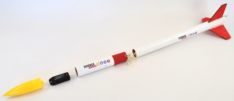 Image Credit: Ben Finio, Science Buddies / Science Buddies
Figure 5. A rocket with a payload bay, which can be used to carry cargo like an altimeter.
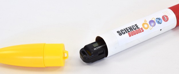 Image Credit: Ben Finio, Science Buddies / Science Buddies
Figure 6. A close-up view of the payload bay. One of the static ports is visible just below the Science Buddies logo. There are two more ports on the other side of the rocket (not visible).
Different electronic sensors record different information. For example, some sensors record certain values that characterize a flight, like the apogee, along with maximum and/or average accelerations, the flight duration, or the amount of time between different points in the flight, like the burn time (how long the engine burns before running out of propellant) (Figure 7). Other sensors may continuously log data throughout the entire flight, producing graphs of altitude and acceleration vs. time when the data is downloaded to a computer or displayed on a smartphone (Figure 8). Either type of sensor should work for measuring the maximum altitude in this project.
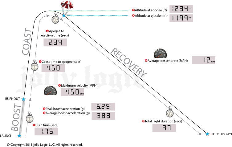 Image Credit: Ben Finio, Science Buddies / Science Buddies
Diagram showing boost, coast, and recovery phases of rocket flight with data recorded by Jolly Logic Altimeter Two, including burn time, peak boost acceleration, average boost acceleration, coast time to apogee, altitude at apogee, altitude at ejection, apogee to ejection time, average descent rate, and total flight duration.
Figure 7. Screenshot from the Jolly Logic Altimeter Two user manual showing all the information that is recorded during a flight. Photo courtesy of Jolly Logic.
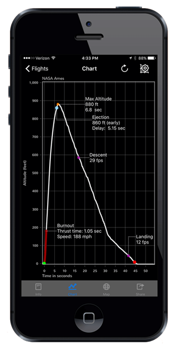 Image Credit: Ben Finio, Science Buddies / Science Buddies
Figure 8. The Jolly Logic Altimeter Three software showing recorded flight data. Photo courtesy of Jolly Logic.
We have briefly covered how you can measure rocket flight, but how can you predict a rocket's motion? You are probably familiar with Newton's second law of motion, which is commonly expressed in equation form as:
Equation 1:where
- F is force, in newtons (N)
- m is mass, in kilograms (kg)
- a is acceleration, in meters per second squared (m/s2)
In high school physics problems, Newton's second law is usually applied to objects with constant mass (for instance, the classic example of a force pushing a block on an inclined plane). However, that presents a problem when applied to rockets: their mass is not constant! Rockets expel high-velocity exhaust in one direction, which pushes the rocket in the other direction due to conservation of momentum. As the engine burns and expels fuel, its mass decreases; therefore, rocket motion is modeled mathematically with the Tsiolkovsky rocket equation (see Bibliography), which takes the rocket's changing mass into account. This equation is extremely important for real rockets that fly into space. Reaching orbit requires so much fuel that the majority—nearly or sometimes exceeding 90%—of a rocket's mass at launch is fuel (this ratio is called the propellant mass fraction).
However, the propellant mass fraction is much lower for model rockets. For example, the model rocket at the bottom of Figure 1 (the Apogee Apprentice) has a mass of 60.8 g when loaded with a new A8-3 model rocket engine, and a mass of 54.9 g with a used engine (we will discuss model rocket engines and what the letters and numbers mean below), a difference of 5.9 g. Less than 10% of the rocket's weight at launch is propellant. This means that you can roughly predict a rocket's maximum height using a simplified equation that assumes the rocket's mass is constant. This height is the sum of the height the rocket reaches at the end of its boost phase plus the additional height it gains during the coast phase.
Equation 2:where
- hmax is the rocket's maximum height, in meters (m).
- aboost is the rocket's acceleration during the boost phase, in meters per second squared (m/s2).
- vmax is the rocket's maximum velocity, which is achieved at the end of the boost phase, in meters per second (m/s).
- g is acceleration due to gravity, which is 9.81 meters per second squared (m/s2). Note: Do not plug negative 9.81 into the equation, the minus sign is already accounted for.
To solve for the maximum height in this equation, first you need to find the boost phase acceleration, aboost, and the maximum velocity, vmax. The average acceleration during the boost phase can be calculated using Newton's second law (see technical note):
Equation 3:where
- aboost is the rocket's acceleration during the boost phase in meters per second squared (m/s2)
- Tavg is the engine's average thrust in newtons (N)
- mavg is the rocket's average mass in kilograms (kg)
- g is acceleration due to gravity, which is 9.81 meters per second squared (m/s2). Note: do not plug negative 9.81 into the equation, the minus sign is already accounted for.
The maximum velocity can be calculated using the equations of motion for constant acceleration (see Technical Note):
Equation 4:where
- vmax is the rocket's maximum velocity, in meters per second (m/s).
- aboost is the rocket's acceleration during the boost phase, in meters per second squared (m/s2).
- tburn is the engine's burn time, in seconds (s).
You can measure the mass of your rocket yourself, but where do you find out the engine thrust and burn time? You will need to look up that information from the manufacturer (note: information from the manufacturer may not always be 100% reliable, but it is a good place to start. See the Technical Note about rocket engines for more details). For example, look at this page for the popular Estes A8-3 engine and click on "Technical Specifications." You will see that it lists a "Total Impulse" of 2.50 N-sec and a "Thrust Duration" of 0.50 sec (thrust duration is another way of saying "burn time"). An impulse is a force that is applied for a certain amount of time. If you know the total impulse and amount of time, you can calculate the average force using this equation:
Equation 5:where
- J is impulse, in newton-seconds (N-s).
- Favg is average force, in newtons (N).
- Δt is change in time, in seconds (s).
See the Technical Note for the full derivation of these equations. Even if you do not understand all the physics to derive the equations yourself, you should understand that it relies on a few assumptions:
- As discussed above, the physics assumes the rocket's mass is constant. It ignores the change in mass due to the engine burning propellant.
- It ignores air resistance.
- It assumes the rocket moves straight up in a vertical line. It ignores any horizontal motion due to wind or launching the rocket at an angle.
That is a lot of information to absorb! Take your time to review this introduction, the references in the Bibliography, and the terms and questions before you proceed. Once you have done so, you should be prepared to do a science project with independent and dependent variables involving a model rocket. For example, you can test different rocket engines with different total impulses. You can predict your rocket's maximum height using Equation 2, measure its maximum height using an altimeter, then compare your theoretical and experimental results. For other ideas, see the Variations section. Now, get ready to do some rocket science!
You might be wondering where Equations 2–4 come from. They are derived from analyzing the rocket's vertical motion using the constant acceleration equations, which you can find in most physics textbooks. These equations allow you to calculate the position and velocity of an object that has a constant acceleration (note: deriving these equations requires the use of calculus—if you have not taken calculus yet, you can just accept the information for now). You may also hear them referred to as the "one-dimensional (1D) kinematic equations," meaning they describe the motion of an object moving in a straight line. The four main equations are:
Equation 6:Equation 7:
Equation 8:
Equation 9:
where
- d is the object's displacement (distance traveled), in meters (m).
- t is the elapsed time, in seconds (s).
- vi is the initial velocity, in meters per second (m/s).
- vf is the final velocity, in meters per second (m/s).
- a is the constant acceleration, in meters per second squared (m/s2).
Using these equations, along with Newton's second law (Equation 1), you can calculate a rocket's maximum height by adding up the distances traveled during its two upward phases of flight (boost and coast). Figure 9 shows a diagram with information about the rocket's flight, including known and unknown variables.
- At point 1, the rocket launches from the ground. It starts with zero velocity and a height of zero.
- During the boost phase, thrust from the engine (T) pushes the rocket upward, and gravity pulls it down. The net upward force on the rocket is the engine thrust minus the rocket's weight (W). The acceleration during this phase can be calculated with Newton's second law.
- At point 2, the engine burns out and the rocket transitions to the coast phase. The rocket's height and velocity at this point are unknown, but can be solved for using the constant acceleration equations.
- During the coast phase, there is no longer any thrust acting on the rocket. The only force acting on the rocket is its own weight pulling it down (ignoring air resistance). The acceleration during this phase is equal to the acceleration due to gravity, -9.81 m/s2 (assuming we have defined up as the positive direction).
- At point 3 (the apogee), the rocket has reached its maximum height. The height is unknown, but importantly, the velocity at this point will be zero. At the apogee, the rocket's velocity briefly becomes zero before it becomes negative and the rocket starts to fall back to the ground.
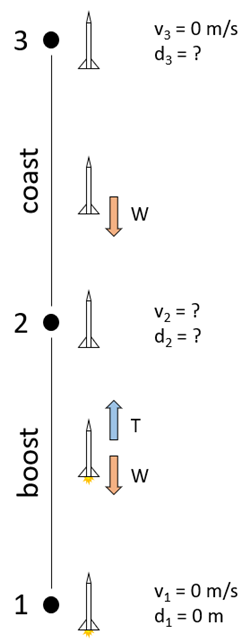 Image Credit: Ben Finio, Science Buddies / Science Buddies
Figure 9. Diagram of the boost and coast phases of the rocket's flight, with known and unknown variables labeled.
Calculating the acceleration during the boost phase comes from writing Newton's second law, where the net upward force on the rocket is the thrust minus the weight:
Equation 10:Rearranging Equation 10 to solve for the acceleration gives the acceleration during the boost phase (the same as Equation 3 above):
Equation 11:The distance and velocity at point 2 can be calculated using Equations 6 and 7, respectively, filling in the known information from Figure 9 (you know the initial velocity at point 1 is zero, so the vi term in Equations 6 and 7 cancels out):
Equation 12:
Equation 13:
Note that the velocity at point 2 will be the rocket's maximum velocity. When the engine burns out, it will stop accelerating and start decelerating. This means that
Equation 14:
Now you can calculate the distance traveled during the coast phase using Equation 8, because you know the final velocity at point 3 is zero. Rearranging Equation 8 to solve for this distance gives the following (remember that the acceleration during the coast phase is equal to -g)
Equation 15:
However, this is the distance traveled from point 2, not from the ground. To get the total distance traveled (the distance at point 3), you need to add the distances from Equations 12 and 13. This gives you
Equation 16:which is the same as Equation 2, (except there we used "h" for "height" instead of "d" for "displacement").
Model rocket engines are labeled with a letter-and-number scheme, such as A8-3, where:
- The letter indicates the possible range for the total impulse of the engine in newton-seconds (N-s). See the "All About Rocket Engines" reference in the Bibliography for a table with the letters and ranges of impulse values.
- The first number is the average thrust of the engine, in newtons (N).
- The second number is the delay time, in seconds (s). This is the amount of time after the propellant finishes burning until the ejection charge ignites, which helps deploy the parachute.
However, different manufacturers might not be consistent about their use of this naming scheme, so you should not take it at face value. For example, the technical specifications page for the popular Estes A8-3 engine lists a total impulse of 2.5 N-s and a thrust duration of 0.5 s. According to Equation 3, rearranging to solve for Favg gives an average force of 2.5/0.5 = 5 N. However, according to the name A8-3, the average force should be 8N! Which value should you believe? The National Association of Rocketry performs their own tests on rocket motors, and their list of NAR Certified Motors is a good source to verify motor specifications. Their tests for the Estes A8 and Quest A8 motors show average thrusts of 4.03 N and 4.84 N, respectively—neither of which matches the value you would expect from the name! Depending on which values you use, you will get different results from Equation 2.
Terms and Concepts
- Nose cone
- Recovery system
- Fins
- Engine
- Boost
- Thrust
- Coast
- Apogee
- Recovery
- Accelerometer
- Altimeter
- Payload bay
- Static ports
- Burn time
- Newton's second law of motion
- Conservation of momentum
- Tsiolkovsky rocket equation
- Propellent mass fraction
- Impulse
- Constant acceleration equations
- Delay time
- Ejection charge
Questions
- Which forces act on a model rocket during flight?
- What factors influence the maximum height that a rocket will reach?
- How can you use math and physics to predict a rocket's maximum height?
- How can you measure a rocket's maximum height?
- What do the letter-and-number labels on a model rocket engine mean?
Bibliography
These references provide introductory information about model rockets:
- NAR. (n.d.). The National Association of Rocketry. Retrieved August 3, 2020.
- Apogee Components. (n.d.). New to Model Rocketry?. Retrieved August 3, 2020.
- NASA. (n.d.). Guided Tours of the Beginner's Guide to Aeronautics (BGA). Retrieved August 3, 2020.
- Stine, G.H. and Stine, B. (2004, April 22). Handbook of Model Rocketry, 7th Edition. John Wiley & Sons, 2004.
These references explain Tsiolkovsky's rocket equation in more detail:
- NASA. (n.d.). Ideal Rocket Equation. Retrieved August 3, 2020.
- Pettit, D. (2012, May 1). The Tyranny of the Rocket Equation. NASA. Retrieved August 3, 2020.
These references explain how you can predict the (vertical) trajectory of your model rocket's flight:
- Hardin, S. (2012, August 28). Compute How High and Fast Your Rocket Goes Using the Basic Equations of Rocket Motion. Apogee Components Peak of Flight Newsletter. Retrieved August 3, 2020.
- Henderson, T. (n.d.). The Kinematic Equations. The Physics Classroom. Retrieved August 3, 2020.
These references contain more information about model rocket engines:
- NASA. (n.d.). Model Rocket Engine Designation. Retrieved August 3, 2020.
- LUNAR. (2008, January). All About Rocket Engines. Retrieved August 3, 2020.
- National Association of Rocketry. (2020, May 17). NAR Certified Motors. Retrieved August 6, 2020.
These references explain how to calculate the required static port diameter based on the size of your rocket's payload bay:
- Schiff, J. (2010, June 1). Mathematics in Amateur Rocketry. Apogee Components Peak of Flight Newsletter. Retrieved August 5, 2020.
- Knowles, V. (n.d.). Altimeter Port Sizing. Vern's Rocketry. Retrieved August 5, 2020.
Materials and Equipment
You will need to decide exactly what to purchase for this project based on your budget, how many trials you want to do, etc. There are multiple options, so we did not write the instructions for a specific model of rocket or altimeter. Model rocket supplies are available at many hobby stores. Supplies are also available from Estes Rockets and Apogee Components . Remember to review the "What All Do I Need For a Model Rocket Launch?" section on the New to Model Rocketry? page if you are new to model rocketry and not sure what supplies you need, but here is an overview:
- Model rocket with payload bay
- Altimeter
- You will need mounting hardware or tape to attach the altimeter inside your rocket's payload bay (check manufacturer recommendations).
- Make sure you buy an altimeter that is intended for use with model rockets and will fit in your rocket's payload bay. Such altimeters are typically only a few centimeters long and may only weigh a few grams.
- Most model rocket altimeters will record maximum altitude. Some will record additional data. Make sure you understand what data your altimeter will record and how you will access it. For example, does the altimeter display the data on a built-in screen, connect to your phone, or do you need to download the data to a computer?
- Launch controller and launch pad
- Engines (at least 3 of each type you plan to test). A-sized engines are best if this is your first model rocket project. Your rocket will not go as high, but it will be easier to recover. For example, you could compare Estes 1/2A6-2 engines to Estes A8-3 engines. B-sized engines and above are best for students who already have some experience with model rockets and access to a larger launch site.
- Recovery wadding
- Tools and supplies for assembling your rocket. You will need to read the manufacturer's instructions for your rocket, but these typically include a hobby knife, ruler, pencil, wood glue, and plastic cement or superglue.
- Materials to finish, paint, and/or decorate your rocket, such as sandpaper, spray paint, and stickers
- Kitchen scale to weigh your rocket, with at least 0.1 g sensitivity
- Large, open field free of obstructions like trees and power lines in which to launch your rocket. Refer to the Model Rocket Safety Code for required launch site dimensions.
- Helpers can be useful when launching the rocket, such as a spotter to carefully watch where the rocket lands or to take photos/video from a distance while you operate the launch controller
- Lab notebook
Disclaimer: Science Buddies participates in affiliate programs with Home Science Tools, Amazon.com, Carolina Biological, and Jameco Electronics. Proceeds from the affiliate programs help support Science Buddies, a 501(c)(3) public charity, and keep our resources free for everyone. Our top priority is student learning. If you have any comments (positive or negative) related to purchases you've made for science projects from recommendations on our site, please let us know. Write to us at scibuddy@sciencebuddies.org.
Experimental Procedure
- Plan out your experiment. Review the Background section if you are not sure how to answer the following questions.
- What independent variable will you change on your rocket?
- What dependent variable will you measure?
- How will you calculate a theoretical value for the dependent variable?
- How will you measure the dependent variable, experimentally? How will you access the data?
- Does your altimeter store data for multiple flights? Will you need to download the data to a computer in between each flight?
- When and where will you launch your rocket? How many trials will you do? What is your backup plan if you are unable to recover your rocket? For example, is there a risk of your rocket getting stuck in a tree? Will you have the time and money to buy another rocket in time to do your science project? How would this affect your results?
- Will you be able to perform all your launches on the same day, in a relatively short period of time? If not, how could variable weather affect your experiment?
- Prepare a data table for your results. Table 1 shows an example data table. Remember that your table may be different depending on your independent and dependent variables. For model rocket projects, it is also a good idea to record observations about the weather and launch conditions. You could record these in a separate data table (Table 2) or include them in your main table.
| Engine | Maximum Height (m) | ||||||||
|---|---|---|---|---|---|---|---|---|---|
| Name | Total Impulse (N-s) | Burn time (s) |
Average thrust (N) |
Trial 1 | Trial 2 | Trial 3 | Average | Theoretical | Difference (Theoretical - Average) |
| Engine | Trial | Wind Speed (km/h) | Wind Direction | Temperature (°C) | Other notes |
|---|---|---|---|---|---|
| 1 | |||||
| 2 | |||||
| 3 |
- Perform your theoretical calculations for your rocket's maximum height (or, if you are too excited to go launch your rocket, you can do this step later!). You may want to create a separate data table to record values as you do your calculations (Table 2), or you could do the calculations in a spreadsheet program.
- Look up the total impulse and burn time for your motor.
- Use Equation 5 from the Background to calculate your motor's average thrust.
- Calculate your rocket's average mass (the average between new and used engines). You will either need to launch a rocket first so you can measure a used engine, or look up the mass of a used engine online.
- Use Equation 3 from the Background to calculate your rocket's average acceleration during the boost phase.
- Use Equation 4 from the Background to calculate your rocket's maximum velocity at the end of the boost phase.
- Use Equation 2 from the Background to calculate your rocket's maximum height.
| Motor Name | Total Impulse (N-s) | Burn Time (s) |
Average Thrust (N) | Rocket Average Mass (kg) |
aboost (m/s2) | vmax (m/s) | hmax (m) |
|---|---|---|---|---|---|---|---|
- Follow the manufacturer's instructions to assemble your rocket.
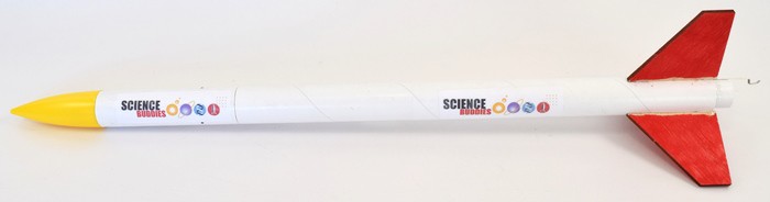 Image Credit: Ben Finio, Science Buddies / Science Buddies
Figure 10. An assembled Apogee Research Express rocket.
- Follow the manufacturer's instructions to set up your altimeter. These may include (but not be limited to):
- How to charge the altimeter's battery.
- How to download and use software to access the altimeter's recorded data.
- How to drill static ports in your rocket's payload bay for the altimeter.
- How to install the altimeter in your rocket's payload bay. This step is important so the altimeter does not fall out when the ejection charge fires to deploy the parachute (as this author learned the hard way)!
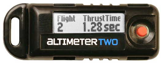 Image Credit: Jolly Locig / Jolly Logic
Figure 11. The Jolly Logic Altimeter Two. Photo courtesy of Jolly Logic.
- Make sure you have everything you need to launch your rocket! This might not be a big deal if you can launch your rocket from your backyard, but if you need an adult to drive you somewhere (like a nearby park or soccer field), it will be frustrating if you forget a small part like recovery wadding or motor igniters. Bring everything you will need to conduct multiple launches.
- Follow the instructions for your rocket, launch pad/controller, and altimeter, along with the National Association of Rocketry's Model Rocket Safety Code to launch your rocket.
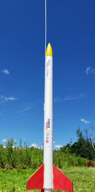 Image Credit: Ben Finio, Science Buddies / Science Buddies
Figure 12. A model rocket on the launch pad.
- Recover your rocket. If needed, download or record the data from your altimeter.
- Repeat steps 7–8 as many times as needed in order to collect all your data.
- Analyze your experimental results. Graphing the data may be helpful.
- Are the results what you expect?
- Is there a trend or relationship between your independent and dependent variables?
- How repeatable were your results? Are there any outliers or measurements that seem erroneous? For example, did your altimeter report that your rocket only went 10 ft. in the air when you could clearly see that it went over 100 ft? If so, it is possible that your altimeter was accidentally triggered before launch—for example, by bumping the rocket on the launch pad? You may need to repeat the trial if this occurs.
- Are there any other potential sources of error or variation in your experimental results? For example, how variable were the weather conditions? Did you perform some launches in calm weather and others in a steady breeze or a gusty wind?
- Compare your experimental results and theoretical predictions. Showing the results on the same graph may be helpful.
- Do the theoretical predictions show the same trend as your experimental results?
- How close are they to the experimental results?
- Make sure you review the assumptions used for Equation 2 in the Background section. How might these assumptions affect the accuracy of your theoretical results?
Ask an Expert
Global Connections
The United Nations Sustainable Development Goals (UNSDGs) are a blueprint to achieve a better and more sustainable future for all.

Variations
- Other ideas for your independent variable could include:
- Use engines with the same total impulse, but different average thrust, for instance, a B4-2 versus a B6-2.
- Compare engines with the same rating from different manufacturers.
- Use the same type of engine for all trials, but put additional mass in the rocket's payload bay.
- There are other aspects of your rocket's flight that you can calculate using the equations of motion presented in the Background section. You can also measure some of these parameters with an altimeter (you will need to check the manufacturer's instructions to see exactly what your altimeter can measure). How do theoretical and experimental results compare for these variables? For example:
- What is the rocket's maximum velocity?
- At what altitude does the rocket achieve maximum velocity?
- How long does it take the rocket to reach its apogee?
- Based on the engine's delay time, at what altitude will the rocket eject its parachute?
- How fast will the rocket be going when it ejects its parachute?
- As discussed in the Technical Note in the Background, the manufacturer ratings for rocket engine performance may not always be consistent with the engine naming convention, and testing by the National Association of Rocketry might give different values as well. That gives you three different, potentially conflicting, sources of information about the engine! How much do your theoretical results vary when you use information from the different sources in Equation 2? Which source seems to be the most accurate?
- You can analyze your rocket's motion using a video of the launch. Set up a camera on a tripod aimed at the launch pad and film the launch. Using an object of known size in the video frame, in the same plane as the launch pad, will give you a scale for the video (for example, a meterstick or a person). You can then use video analysis software to track the rocket's location in the video, and convert this location in pixels to real-world distance in meters. If you know the camera's frame rate (the number of still images taken per second), you can also calculate velocity and acceleration. Many cameras film at 30 or 60 frames per second (fps), but some smartphones offer slow-motion video modes that capture at 120 fps, 240 fps, or even higher! Note that this approach might work to film the beginning of your rocket's flight, but it can be difficult to place a camera far enough away to film the entire flight while fixed on a tripod.
- You can use computer simulation software to predict your rocket's performance. This software makes it easier to account for calculations that are much more difficult to do by hand, like the effects of wind gusts on rocket stability. RockSim is a simulation program available from Apogee Components.
- Testing different fin shapes is a popular topic for a model rocket science project, but be careful! Fin shape can have a very subtle and hard-to-measure effect on rocket performance. For example, the average thrust and burn time of individual motors can vary by about +/-5% (see NAR motor testing data linked in the Background section). Unless you do many, many trials, it can be hard to tell if something like a 3% difference in altitude between two flights is due to different fins or simply variations in motor performance (or other factors like wind).
Careers
If you like this project, you might enjoy exploring these related careers:


Related Links
- Science Fair Project Guide
- Other Ideas Like This
- Physics Project Ideas
- Space Exploration Project Ideas
- My Favorites