I am having a problem with my robot instructions. Under the "wiring the electronics" portion of instructions, letter B says that I need to sacrifice some of the breadboard wire for the wires that run to the sensors. I do not know where to find this "breadboard wire". (ps: i did buy the recommended electronics kit from Jameco.) Please tell me what i am not seeing, that is probably not right in front of me.
Thanks,
Jordan
Line Follower Robot Wiring Problem
Moderators: kgudger, bfinio, MadelineB, Moderators
-
JordanHorne
- Posts: 6
- Joined: Wed Apr 29, 2015 6:00 pm
- Occupation: Student: 10th grade
- Project Question: I am doing the line follower robot project. In the wiring portion, under letter B, it says that i need to sacrifice some breadboard wire, I am not quite sure where that is. (PS: I did buy the recommended electronics kit from Jameco Electronics.
- Project Due Date: 5/14/15
- Project Status: I am just starting
-
deleted-249560
- Posts: 496
- Joined: Thu Nov 20, 2014 1:35 pm
- Occupation: Science Buddies content developer
- Project Question: N/A
- Project Due Date: N/A
- Project Status: Not applicable
Re: Line Follower Robot Wiring Problem
Jordan-
That is indeed a problem and I'll have to ask Jameco what happened to the breadboard wires in the kit. I see they're no longer included in the parts list but they charge less for the kit now. No worries though.
There are two types of breadboard wires available these days. I'm not suggesting any one specific place to buy them, but rather using these links to show you the pictures. You can get breadboard wires at Radio Shack if you have one in your area or at many good mail order places.
The newer soft kind of wires are flexible but have rigid tips: http://www.makershed.com/products/delux ... mper-wires
The older type are simply solid wire of the correct diameter for breadboards that has been prestripped for your convenience: http://www.jameco.com/webapp/wcs/stores ... 2134993_-1 or http://www.radioshack.com/solderless-br ... es&start=3

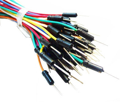
You may recognize the smaller ones (that sort of look like staples) in the image as the ones in the project instructions.
The idea behind those instructions is that the smaller flexible wire from the ribbon cable would be easier to attach to the sensor and motors, but then you couldn't plug it into the breadboard. So my solution was to have you attach the breadboard ends to rigid pieces of wire. And the easiest way of doing that was to use one of the short breadboard wires - cut it in half and use each half as one of the rigid tips.
You need breadboard wires anyway to connect the components. So I'd suggest you find a wiring kit of your choice at Radio Shack (or other local electronics store) or mail order. Or if you'd rather, a hardware store or big box home center may sell spools of wire. Breadboards like 22 gauge solid copper wire. You can get a small spool of that and a wire stripper and make your own breadboard wires. Whatever your solution, you just want to make the 4 wires from the sensor and the 4 wires from the motors (2 wires per motor) are rigid enough to plug into the breadboard with your other components.
Howard
That is indeed a problem and I'll have to ask Jameco what happened to the breadboard wires in the kit. I see they're no longer included in the parts list but they charge less for the kit now. No worries though.
There are two types of breadboard wires available these days. I'm not suggesting any one specific place to buy them, but rather using these links to show you the pictures. You can get breadboard wires at Radio Shack if you have one in your area or at many good mail order places.
The newer soft kind of wires are flexible but have rigid tips: http://www.makershed.com/products/delux ... mper-wires
The older type are simply solid wire of the correct diameter for breadboards that has been prestripped for your convenience: http://www.jameco.com/webapp/wcs/stores ... 2134993_-1 or http://www.radioshack.com/solderless-br ... es&start=3
You may recognize the smaller ones (that sort of look like staples) in the image as the ones in the project instructions.
The idea behind those instructions is that the smaller flexible wire from the ribbon cable would be easier to attach to the sensor and motors, but then you couldn't plug it into the breadboard. So my solution was to have you attach the breadboard ends to rigid pieces of wire. And the easiest way of doing that was to use one of the short breadboard wires - cut it in half and use each half as one of the rigid tips.
You need breadboard wires anyway to connect the components. So I'd suggest you find a wiring kit of your choice at Radio Shack (or other local electronics store) or mail order. Or if you'd rather, a hardware store or big box home center may sell spools of wire. Breadboards like 22 gauge solid copper wire. You can get a small spool of that and a wire stripper and make your own breadboard wires. Whatever your solution, you just want to make the 4 wires from the sensor and the 4 wires from the motors (2 wires per motor) are rigid enough to plug into the breadboard with your other components.
Howard
-
JordanHorne
- Posts: 6
- Joined: Wed Apr 29, 2015 6:00 pm
- Occupation: Student: 10th grade
- Project Question: I am doing the line follower robot project. In the wiring portion, under letter B, it says that i need to sacrifice some breadboard wire, I am not quite sure where that is. (PS: I did buy the recommended electronics kit from Jameco Electronics.
- Project Due Date: 5/14/15
- Project Status: I am just starting
Re: Line Follower Robot Wiring Problem
Thanks so much!! I will check Radioshack and see if they have some.
-
JordanHorne
- Posts: 6
- Joined: Wed Apr 29, 2015 6:00 pm
- Occupation: Student: 10th grade
- Project Question: I am doing the line follower robot project. In the wiring portion, under letter B, it says that i need to sacrifice some breadboard wire, I am not quite sure where that is. (PS: I did buy the recommended electronics kit from Jameco Electronics.
- Project Due Date: 5/14/15
- Project Status: I am just starting
Re: Line Follower Robot Wiring Problem
Those wires worked great. Thanks! I do have another problem. After I finished the first side of wires, and it worked great, but then I finished the other side, and it would not work. I know it wasn't the motor because I did what says by putting the one wire from the motor directly into the blue bus, and it worked, but there were no controls. It was just move or not. Here is a picture to show what I've done. you might be able to see if bleep is wrong. /Users/jordanhorne/Downloads/IMG_1563..JPG
-
deleted-249560
- Posts: 496
- Joined: Thu Nov 20, 2014 1:35 pm
- Occupation: Science Buddies content developer
- Project Question: N/A
- Project Due Date: N/A
- Project Status: Not applicable
Re: Line Follower Robot Wiring Problem
Jordan-
I'm glad to hear you've made some progress and got one side to work. I suspect you have a wiring problem and I'll cross my fingers and hope you didn't damage either the light sensor or the power transistor. Unfortunately your picture didn't post so there's not much I can suggest to help. Obviously I'd say go back and check your wiring carefully and make sure you didn't reuse any of the breadboard rows from the first side on the second side. There's no connection between left and right at all except for the red and blue (positive and negative) power busses.
If you want to take another try at photographing your board I'll be happy to take a look.
Howard
-
JordanHorne
- Posts: 6
- Joined: Wed Apr 29, 2015 6:00 pm
- Occupation: Student: 10th grade
- Project Question: I am doing the line follower robot project. In the wiring portion, under letter B, it says that i need to sacrifice some breadboard wire, I am not quite sure where that is. (PS: I did buy the recommended electronics kit from Jameco Electronics.
- Project Due Date: 5/14/15
- Project Status: I am just starting
Re: Line Follower Robot Wiring Problem
I got it working this morning! It was the wires going in to wrong rows of the transistor. I do have one other question. In the picture with the actual wired breadboard, it shows pieces of long breadboard wires going across the breadboard, and I do not see the instructions on where to put those. There are also several other wires on it that I do not see in the instructions. Can you tell me where the instructions are for those wires?
-
deleted-249560
- Posts: 496
- Joined: Thu Nov 20, 2014 1:35 pm
- Occupation: Science Buddies content developer
- Project Question: N/A
- Project Due Date: N/A
- Project Status: Not applicable
Re: Line Follower Robot Wiring Problem
The long diagonal red wires in that photo simply connect the red buss on one side to the red on the other, and the blue buss on one side to the other blue buss. That seemed like a good idea to help keep the left and right sides of the wiring visually separate but you dont have to do it that way. The instructions include some vagueness on purpose since I coujldn't be sure how your specific breadboard would look. Some students have done it with smaller ones that don't have the red and blue buss connections.
Which other wires are you referring to?
Congratulations on finding the problem! I hope you'll consider posting a video of your working robot.
Howard
Which other wires are you referring to?
Congratulations on finding the problem! I hope you'll consider posting a video of your working robot.
Howard
-
JordanHorne
- Posts: 6
- Joined: Wed Apr 29, 2015 6:00 pm
- Occupation: Student: 10th grade
- Project Question: I am doing the line follower robot project. In the wiring portion, under letter B, it says that i need to sacrifice some breadboard wire, I am not quite sure where that is. (PS: I did buy the recommended electronics kit from Jameco Electronics.
- Project Due Date: 5/14/15
- Project Status: I am just starting
Re: Line Follower Robot Wiring Problem
http://www.cdn.sciencebuddies.org/Files ... dboard.jpg. I was looking at the green wires near the battery case.
-
deleted-249560
- Posts: 496
- Joined: Thu Nov 20, 2014 1:35 pm
- Occupation: Science Buddies content developer
- Project Question: N/A
- Project Due Date: N/A
- Project Status: Not applicable
Re: Line Follower Robot Wiring Problem
Those green wires connect one side of the motor to the positive power buss. I did that because I thought it was aesthetically better to have the motor wires together than to split them apart. You probably just stuck the motor wires directly into the red buss which is fine. Artistic license perhaps?
Howard
Howard
-
JordanHorne
- Posts: 6
- Joined: Wed Apr 29, 2015 6:00 pm
- Occupation: Student: 10th grade
- Project Question: I am doing the line follower robot project. In the wiring portion, under letter B, it says that i need to sacrifice some breadboard wire, I am not quite sure where that is. (PS: I did buy the recommended electronics kit from Jameco Electronics.
- Project Due Date: 5/14/15
- Project Status: I am just starting
Re: Line Follower Robot Wiring Problem
Oh okay. I do have one question now that it is finished. When I would put the robot on a line, which I just use electrical tape to make an exact line, it would work fine for a little bit, then slow down and act like the battery is going dead and one wheel would move constantly, and then a while later it would be fast following the line great. Any suggestions?
-
deleted-249560
- Posts: 496
- Joined: Thu Nov 20, 2014 1:35 pm
- Occupation: Science Buddies content developer
- Project Question: N/A
- Project Due Date: N/A
- Project Status: Not applicable
Re: Line Follower Robot Wiring Problem
From the description I'm not quite sure what that looks like, but one thing I can suggest is that the sensor works best when the black line is as non-reflective as possible. You said you're using electrical tape? That's pretty shiny. If the sensor is halfway between seeing the IR bounce back and not then the motor will turn on and off rapidly and might cause the behavior you describe.
As a test, try the robot on a piece of paper and draw a line with a marker. I know it won't be pretty and even but this is just a test. If the robot works better than the shiny tape is your problem. You can get black gaffer's tape and cut off strips, or art stores sometimes sell black crepe tape. Auto parts stores and large box home repair stores also sell masking tape in narrow widths. You can use a strip of that, color it black with a marker and that should be non-shiny.
Howard