Thanks for anyone who takes the time to read this and respond.
I have a problem getting the How Does the Intensity of Light Affect the
Power Output of Solar Cells project to work, and I've brought all of the materials. Part of the problem could be because in this project, you don't provide pictures of how the result should look, like in your Rock'n Roll Radios one. If you can, could you send me at least one picture of how everything should look like, since I brought all the materials and tried to assemble it but it wouldn't work.
Secondly, could you tell me exactly how to Wire the volt meter and the LED together and how to connect those to a solar cell (and the exact type of wire nessecary, since mine might be too thin). Also could you tell me exactly where to put the wires on the solar cell for it to be connected?
Thanks
Help with the setup of an Electricity & Electronics proj
-
Rocket Man
- Posts: 9
- Joined: Mon Dec 20, 2004 4:47 pm
-
deleted-71413
- Former Expert
- Posts: 6
- Joined: Wed Nov 17, 2004 12:28 pm
you might find this site useful:
http://www.solarbotics.net/starting/200 ... l_use.html
http://www.solarbotics.net/starting/200 ... l_use.html
-
EDS
- Former Expert
- Posts: 67
- Joined: Thu Nov 18, 2004 4:23 am
Re: Help with the setup of an Electricity & Electronics
Hi Rocket Man,
I gather from your post that you're referring to this science fair project suggestion. (I'm including it here to make it easy for other people who browse the forum to find.)
https://www.sciencebuddies.org/mentorin ... p004.shtml
I didn't have anything to do with writing the project suggestion, but I have some experience with electronics and would be happy to help talk you through the experiment.
As far as the type of wire goes, it probably isn't an issue. You'll only be drawing a tiny amount of current (the number of electrons flowing through the wire per second, times some constants to make the units work out). Almost any wire will work, although if it's really thin it might be hard to handle. Also, some of the really, really tiny wire that people use for winding coils looks like it's just metal wire, but it's actually got insulation painted on it which has to be removed to make electrical contact.
If you're going to buy new wire, bleep like 22 gauge wire is a fine choice. Somewhat bigger or smaller would be fine too. Stranded wire, which is made up of a bunch of little wires all twisted together, would be easier to use if you're going to use screws or solder to connect wires together. Solid wire will be easier to use if you're going to use crimp-on connectors. (See discussion below.) Either can be made to work, though.
How to connect things together may be a little bit tricky. The easiest way is to use wires that have little clips on the ends of them, usually called "alligator clips." Radio Shack sells them in packages of 8 for five dollars. You may also be able to borrow some from a science teacher at school if you can't buy them.
If that isn't an option, then I'm sure we can make bleep work. We'll need to think a little harder about what tools you have available at home. Some options:
If your family has a soldering iron, that would work. But most people don't have one.
If you have a set of crimp-on wire connectors and a crimper, then that will work. They're used to put connectors on the ends of wire for automotive wiring or repairing household appliances.
If you have some wire-nuts - cone shaped plastic things, about half an inch long, with a threaded screw hole in the end - those would work too. They're often used in household electrical wiring.
If you don't have access to any of those, then you can make the connections using metal screws and nuts. (Any size will work, but if you are going to buy new ones bleep like a 1/2 inch long 8-32 screw with a matching nut is probably a good choice.)
Remove about 1/2 inch of insulation from the end of the two wires you want to connect, using a wire stripper if you have one or a sharp knife or razor blade if you don't. Hold them together so the ends face the same direction, and twist the ends together. Then wrap the twisted ends around a screw, and tighten a nut on it to hold the wires in place. Don't let the screws touch anything metal or each-other. (It's not dangerous, but you'll short out the circuit and it won't work.)
I'll throw together a quick diagram of what I think the author of the project suggestion intended and post it here soon.
One question: what does your volt meter look like? Is it just a meter with two connectors or wires on it that looks like it should be mounted on a piece of equipment, or is it a stand alone box with probes connected to it and an on/off switch and other knobs?
take care,
Erik
-
Guest
One question: what does your volt meter look like? Is it just a meter with two connectors or wires on it that looks like it should be mounted on a piece of equipment, or is it a stand alone box with probes connected to it and an on/off switch and other knobs?
It's from RadioShack. The front has DC Volts from 0-15 and 22-410 in the bottom-left corner (I assume that's the part number). The back has the + and - signs with a wire looped around two connectors.
It's from RadioShack. The front has DC Volts from 0-15 and 22-410 in the bottom-left corner (I assume that's the part number). The back has the + and - signs with a wire looped around two connectors.
-
hzatz
- Former Expert
- Posts: 15
- Joined: Wed Nov 17, 2004 12:09 pm
I'll give it a try...
Hmm... That description of an experiment really leaves a lot out...
A solar cell ought to have two wires coming out of it. If you're lucky, one will be marked as +, and the other -. It shouldn't matter too much if you get things backwards, though, since a solar cell shouldn't generate enough electricity to damage a voltmeter.
First, you want to figure out which way to attach the solar cell. Flip whatever switches are necessary on the voltmeter to get it to measure DC voltage (volts) (not current (amps) or resistance (ohms)). Try attaching one wire of the solar cell to the + connection on the voltmeter, and the other to the -. You'll probably get a voltage reading from that; if not, try switching the wires around.
Just with that setup, you could experiment with different light bulbs and voltage output.
I'm not entirely sure what the LED is for, here. I suppose one could use it to measure current, but I would think that a low value resistor (maybe 1-10 ohms or so) would be more useful. The idea is that, in order to measure current, you need to have some sort of load on the circuit. In other words, the electricity has to be actually doing bleep, like lighting an LED, or heating up a resistor.
Once you're familiar with working with the solar cell, I could try to describe how to measure current... if you still think you need more stuff to make your project work.
I hope that helps.
-
Rocket Man
- Posts: 9
- Joined: Mon Dec 20, 2004 4:47 pm
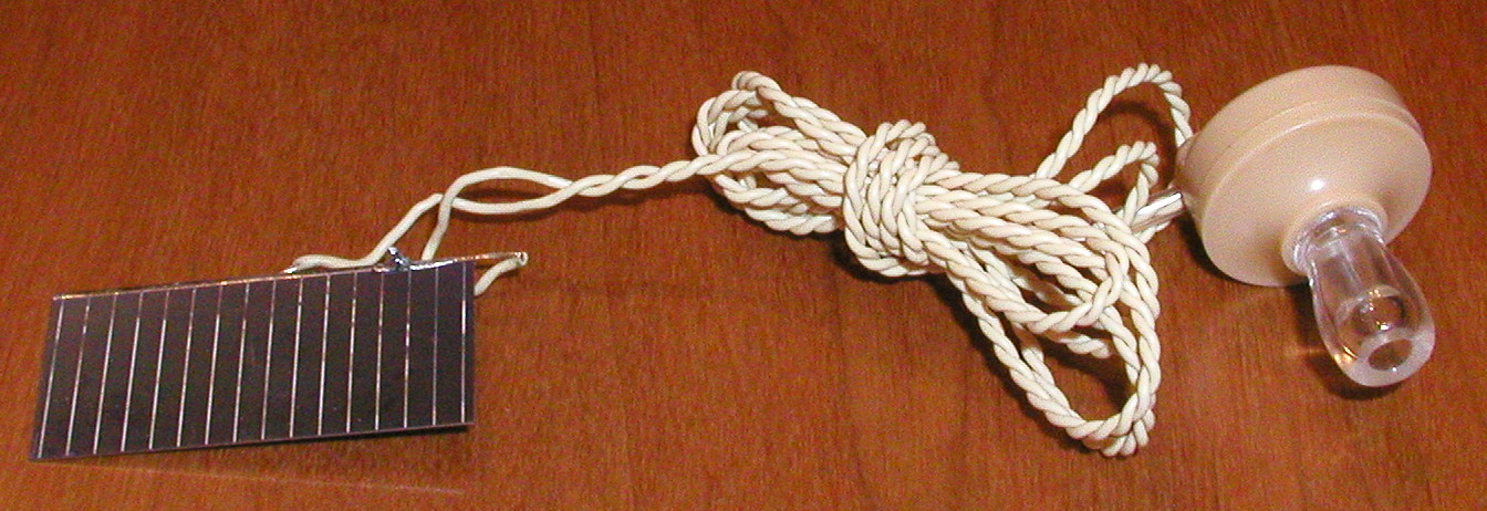
ok thanks everyone i just have one question left and that's how to connect the wires on the bottom of the silicon solar cell (since there's no labels or anything & since mine doesn't come with two wires as in hzatz's description).
My solar cell looks like the one here:
http://sci-toys.com/scitoys/scitoys/lig ... rphone.jpg
and a response within the next day would be greaty appreciated
My solar cell looks like the one here:
http://sci-toys.com/scitoys/scitoys/lig ... rphone.jpg
and a response within the next day would be greaty appreciated
-
davidmoilanen
- Posts: 11
- Joined: Sun Nov 21, 2004 3:09 pm
wire connections
There should be bleep on the solar cell to indicate a place where you can connect some wires even if there aren't wires sticking out of it. Look closely at the solar cell for + and - signs or possibly look at the package that came with the solar cell to see if they have a diagram of it showing where connections can be made. Then take whatever wires you have and figure out a way to make contact with the spots on the solar cell that you think are places where connections can be made. You can solder the wires to the solar cell or just use electrical tape to make a temporary connection. It's hard to give guidance since I don't know what the back of your solar cell looks like but if you examine it closely you should be able to figure bleep out.
David Moilanen
-
EDS
- Former Expert
- Posts: 67
- Joined: Thu Nov 18, 2004 4:23 am
I'm sorry for not getting back to you, Rocketman.
I started to draw up a little diagram of what I *thought* the experiment suggestion intended, and while doing so realized that it wasn't at all clear to me what the author had in mind. I set it aside for a day to think about an appropriate response, and it got sucked into the holiday season vacuum and forgotten. I'm terribly sorry for that, Rocketman.
Davidmoilanen, many thanks for responding. I agree with you that the project as described seems a bit strange. Measuring the open circuit voltage and the current through known loads would be a lot more interesting. Asking students to measure the voltage across an LED isn't likely to tell them much about solar cells. If you ask me, it ought to be re-written or removed from the site.
What's worse, the description calls for a "volt meter" rather than a DMM. Rocketman understandably bought a panel-mount voltage meter with a 15 volt scale. Trying to measure current from a small solar cell with it will be quite a challenge.
Rocketman, in response to your immediate question, if David's suggestions don't help, then you may have to experiment a bit to figure out where to make connections to the solar panel. The appropriate places will almost certainly be metal, and they won't be directly connected to eacother by metal. If you place the solar panel in bright light and play around by connecting the meter to different metal bits, you'll probably find one that works. Depending on how the solar panel is put together, you may only see a couple of volts.
Once you've got the solar panel and the meter hooked up and working, you might want to play around varying the amount of the light hitting the panel to see if anything happens. You could also connect the LED in parallel with the meter (positive sides go together, negative sides go together) to see if the solar panel can make it light up. (It isn't clear that it will be able to do so, but it might.)
If you're interested in going further with it, I'm sure either David or myself could suggest some further experiments that are likely to produce interesting results. You may need a few extra parts though.
Take care,
and sorry once again for leaving you hanging without a response.