/-/https/www.sciencebuddies.org/cdn/Files/21464/5/sb-logo.png)
/-/https/www.sciencebuddies.org/cdn/Files/21464/5/sb-logo.png)
Summary
Part 1 of this lesson is based on the "Reflection on Light" activity from California State University, Long Beach.
/-/https/i.ytimg.com/vi/Fql4TeeqYq8/maxresdefault.jpg)
/-/https/www.sciencebuddies.org/cdn/Files/20511/4/google-classroom.png)
/-/https/www.sciencebuddies.org/cdn/Files/20512/4/ms-teams.png)
/-/https/www.sciencebuddies.org/cdn/Files/20469/4/Canvas_Bug_Color_RGB.png)
/-/https/www.sciencebuddies.org/cdn/Files/20470/5/Schoology-Logo.png)
/-/https/www.sciencebuddies.org/cdn/Files/20471/4/lms.png)
/-/https/www.sciencebuddies.org/cdn/Files/20469/4/Canvas_Bug_Color_RGB.png)
/-/https/www.sciencebuddies.org/cdn/Files/20470/5/Schoology-Logo.png)
/-/https/www.sciencebuddies.org/cdn/Files/20471/4/lms.png)
/-/https/www.sciencebuddies.org/cdn/Files/16578/6/mirror-maze-lp-overview.jpg)
Overview
When light interacts with an object, it can be absorbed, transmitted, or reflected. This lesson focuses on materials that reflect light. Specifically, students will use mirrors and flashlights to investigate how light is reflected from a surface. By doing that, they will discover that when a light ray hits a reflective surface, its angle of incidence is equal to the angle of reflection, which is stated by the law of reflection. Students will then use their gained knowledge in a mirror maze challenge where they have to find a way to guide a light beam through a maze in order to hit a specific target.
Remote Learning: This lesson plan can be conducted remotely. The Engage section of the lesson can be done over a video call, then students can work individually and independently during the Explore sections, using the student worksheet and the maze template as guide. A set of materials can be prepared in advance or students can use materials found around the house. For example, old CDs can work as mirror replacements. The Reflect sections can be done over another video call. Students can show their final design solution either on the call or they can share pictures or drawings of their designs on a class drive.
Learning Objectives
- Understand and explain the law of reflection.
- Guide a light beam through a maze using mirrors.
- Construct and describe a diagram of the light's path as it bounces off reflective surfaces.
NGSS Alignment
This lesson helps students prepare for these Next Generation Science Standards Performance Expectations:- MS-PS4-2. Develop and use a model to describe that waves are reflected, absorbed, or transmitted through various materials.
- MS-ETS1-4. Develop a model to generate data for the iterative testing and modification of a proposed object, tool, or process such that an optimal design can be achieved.
|
Science & Engineering Practices
Planning and Carrying out Investigations.
Conduct an investigation and/or evaluate and/or revise the experimental design to produce data to serve as the basis for evidence that meet the goals of the investigation.
Constructing Explanations and Designing Solutions. Construct a scientific explanation based on valid and reliable evidence obtained from sources (including the students' own experiments) and the assumption that theories and laws that describe the natural world operate today as they did in the past and will continue to do so in the future. Undertake a design project, engaging in the design cycle, to construct and/or implement a solution that meets specific design criteria and constraints Apply scientific ideas or principles to design, construct, and/or test a design of an object, tool, process or system Engaging in Argument from Evidence. Evaluate competing design solutions based on jointly developed and agreed-upon design criteria. |
Disciplinary Core Ideas
PS4.B: Electromagnetic Radiation.
When light shines on an object, it is reflected, absorbed, or transmitted through the object, depending on the object's material and the frequency (color) of the light.
ETS1.B: Developing Possible Solutions. A solution needs to be tested, and then modified on the basis of the test results, in order to improve it. Sometimes parts of different solutions can be combined to create a solution that is better than any of its predecessors. ETS1.C: Optimizing the Design Solution. The iterative process of testing the most promising solutions and modifying what is proposed on the basis of the test results leads to greater refinement and ultimately to an optimal solution. |
Crosscutting Concepts
Patterns.
Patterns can be used to identify cause and effect relationships.
Cause and Effect: Mechanism and Prediction. Cause and effect relationships may be used to predict phenomena in natural or designed systems. |
Materials
/-/https/www.sciencebuddies.org/cdn/Files/16579/6/mirror-maze-materials.jpg)
Per Student Group of 2–3:
- One flashlight with a narrow beam
- 3 small mirror squares (4" x 4")
- 3 squares of aluminum foil (4" x 4")
- 3 pieces of string (about 5" long)
- Colored construction paper (1 sheet)
- 12 clothespins or binder clips
- Masking tape or painter's tape
- Protractor
- Ruler
- Yardstick
- Black cardstock paper (7 sheets)
- One printed maze template
- One printed and cut target from the target template
For Teacher:
- Scissors
- Ruler
- Small mirror square (4" x 4")
- Flashlight with a narrow beam
- Construction paper (1 sheet)
- Piece of string (about 5 inches long)
Background Information for Teachers
This section contains a quick review for teachers of the science and concepts covered in this lesson.Light mostly travels through space in straight lines. This is why, in physics, the concept of light rays is commonly used. In this concept, a light ray is represented as a straight line or arrow pointing away from the light source, which indicates the direction of light (Figure 1, left). A bundle of parallel light rays is called a beam of light (Figure 1, right). Picturing light as lines makes it possible to illustrate what happens if light hits an object that is in its way.
/-/https/www.sciencebuddies.org/cdn/Files/16580/6/light-ray.png)
Figure 1. A straight arrow traveling from a light source depicts a light ray (left) and a group of arrows represents a light beam (right).
Materials can interact with light in different ways. Once light hits a material, the light can either be absorbed, transmitted, or reflected. Often, a combination of absorption, transmission, and reflection happens. How we see a material depends on how the light interacts with the object. We can only see materials that reflect or bounce back at least some light, or materials that emit light themselves. The reflection of light is similar to the bouncing of a ball in that the angle at which the light hits the reflecting surface is identical to the angle at which it bounces off of it (Figure 2). This circumstance is called the law of reflection. The angle that is formed by the light hitting the reflecting surface and the normal line (the line orthogonal to the surface) is called the angle of incidence, whereas the angle between the light bouncing back from the reflective surface and the normal line is called the angle of reflection. Both angles are always equal. Also, the reflected ray, the incident ray, and the normal line all lie in the same plane, the plane of incidence (Figure 2).
/-/https/www.sciencebuddies.org/cdn/Files/16581/6/law-of-reflection-3D.jpg)
A grey trapezoid represents a plane mirror. A line perpendicular to the mirror depicts the normal line. Two arrows pointing at an angle toward the mirror and away from the mirror represent the incident ray and the reflected ray. The angle of incidence and angle of reflection are equal. A rectangle illustrates the plane of incidence.
Figure 2. The law of reflection states that when a light ray hits a reflective surface, its angle of incidence is equal to its angle of reflection.
A mirror is a perfect example of reflection on a smooth material. Because it is so smooth, all light reflects at the same angle (Figure 3, middle) giving the material a shiny appearance. Materials that do not have a smooth surface reflect light in a diffuse way (Figure 3, right). Bumps on their surfaces cause light to reflect in many directions. These materials appear matte.
/-/https/www.sciencebuddies.org/cdn/Files/11971/5/model-reflection.png)
Figure 3. Illustrations of how light reflects on shiny (middle) and matte (right) surfaces.
Using the law of reflection, you can predict where a light ray will go after hitting a smooth, reflective surface such as a mirror. In fact, you can draw a diagram of the light's path through a mirror maze if the incident angle for the first mirror is known. An example of such a diagram is shown in Figure 4.
/-/https/www.sciencebuddies.org/cdn/Files/16582/6/light-path-diagram.jpg)
Figure 4. A diagram showing the path of light through a mirror maze.
In this lesson, students will first investigate the law of reflection with mirrors, construction paper, and a flashlight. Then they will use their gained knowledge in a mirror maze challenge, where they have to use several mirrors to guide a light beam through a maze to hit a specific target.
Additional Background Links
- Light Rays, Britannica
- The Awesome Physics Behind How Mirrors Work, Science Alert
- The Law of Reflection, the Physics Classroom
Prep Work (10 minutes)
- For each student group, prepare the obstacles for their mirror maze. You can review the Mirror Maze Challenge Video for details on how to do that.
- Fold the black cardstock paper in half, lengthwise.
- Now cut the black cardstock paper to the correct widths. Per student group, you will need four 5-in.-wide, four 7.5-in.-wide, and one 10-in.-wide obstacles.
- Fold a little flap on one long side of the obstacles and cut the flap at the halfway point, folding the flaps out in opposite directions to make the obstacles stand up, as shown in Figure 5. Alternatively, you can leave this step to the students.
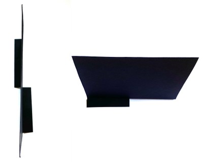
Figure 5. Prepared cardstock obstacle standing up. Top view (left); side view (right).
- Print the target template on white printer or cardstock paper. Prepare one target for each student group. Cut along the continuous line and fold along the dashed line to make the targets stand up like the obstacles. This last step can also be done by the students.
/-/https/www.sciencebuddies.org/cdn/Files/16583/7/preparation-obstacles.jpg)
Teacher Tool Box
Engage (10 minutes)
- Start the lesson by telling students that today they will investigate how light interacts with different objects. Specifically, they will focus on materials that reflect light. Then show students the following video.
- Discuss with students what they have seen in the video.
 What was the problem the Norwegian town had?How did they solve the problem?Why did they use mirrors instead of other materials for their construction on the mountain?
 Have students share their observations. Focus on replies that mention how the mirrors reflect the sunlight into the city square.
 - Continue to ask:
How do you think the townspeople knew where to place the mirrors on the mountain?How can they be sure the reflected sunlight will hit the city square and not another target?Why do you think the mirrors are built so they can track the Sun?Listen to students' ideas. Use their replies to point out that the location of the mirrors is very important and determines to where the light of the Sun is reflected.
- Tell students that they will do an investigation with mirrors and flashlights to find out how exactly a mirror reflects light and how they can be used to guide light to a certain location.
/-/https/i.ytimg.com/vi/1PbAsci1D0k/maxresdefault.jpg)
/-/https/www.sciencebuddies.org/cdn/Files/14174/23/note-question-mark-30.png)
/-/https/www.sciencebuddies.org/cdn/Files/14175/24/conversation-bubbles-30.png)
Part 1: Investigating the Law of Reflection
Explore (30 minutes)
- Divide students into groups of 2–3 and provide each group with one small mirror square, one flashlight, and a piece of colored construction paper.
- Briefly demonstrate how the investigation works. Lay the mirror flat on the table with the shiny side up. Hold the flashlight at an angle pointing down toward the mirror. Explain to students that the light will be reflected off the mirror. Their task is to use the construction paper to catch the reflected light in order to pinpoint exactly where it goes.
- Before students start with their own investigations, introduce the following vocabulary, which will make communicating their results easier. Demonstrate the angle of incidence and the normal line with the flashlight and a piece of string. Do not demonstrate the angle of reflection, as this is for the students to discover. You can add an accompanying drawing for each vocabulary word on the board (Figure 6). Have students record the definition of all these terms in their student worksheet.
- Angle of incidence: The angle that is formed by the light ray falling onto the reflecting surface and the line perpendicular to that surface (the normal line).
- Angle of reflection: The angle that is formed by the light rays bouncing back from the reflective surface and the line perpendicular to that surface (the normal line).
- Normal line: The imaginary line perpendicular to the reflective surface.
/-/https/www.sciencebuddies.org/cdn/Files/16584/6/angle-vocabulary-illustrations.png)
Figure 6. Illustrations of the angle of incidence (left), the normal line (middle), and the angle of reflection (right).
- Instruct student groups to start their independent investigations. Remind them that they should look for a pattern of how the light is reflected off the mirror dependent on how they angle the flashlight toward the mirror. They can use the string to visualize the normal line and the construction paper to catch the reflected light. Their goal is it to formulate a general law of reflection that would allow them to predict where reflected light goes depending on how light shines on a reflective surface.
- Give students 15 minutes to finish their investigations. Tell them to record their observations and their derived law of reflection on their worksheet. While students are working, walk around and check in with them. Listen to their discussions and provide support where needed. Engage students by asking them about their thoughts and observations. Encourage them to outline the angle of incidence and reflection using their fingers. You can ask the following questions to check students' understanding.
How do you know where to hold the construction paper to catch the light?What happens when you hold the flashlight at a different angle?What is the relationship between how you hold the flashlight and where the light goes?
Reflect (30 minutes)
- Once students have finished their experiments, gather the whole class for a group discussion. Ask student groups to share their findings.
Can you describe what you observed during your investigation?Did you notice any patterns in your results?What did you find is the relationship between how you hold the flashlight (angle of incidence) and where the light goes (angle of reflection)?Have students share their results. Encourage them to use the vocabulary presented earlier in the lesson. Allow students to state the law of reflection in their own words. If they have difficulties, help students to formulate that no matter at what angle the light falls on the mirror, the angle of reflection will always be the same as the angle of incidence. Another observation that students should mention is that the incoming light, the normal line, and the outgoing light always lie on the same plane (Figure 2 in the Background Information of the Teachers section).
- Tell students that they have just discovered the law of reflection, which states that when a ray of light reflects off a surface, the angle of incidence is always equal to the angle of reflection.
- Provide students with a ruler and a protractor and ask them to draw a light path diagram on their student worksheet that illustrates the law of reflection. Start out by drawing a plane mirror on a surface and the normal line. Then challenge students to complete the diagram. Besides the mirror and the normal line, the diagram should also show the incident ray of light, reflected ray of light, as well as the angle of incidence and the angle of reflection. The final image should look similar to Figure 7.

A grey rectangle represents a plane mirror. A line perpendicular to the mirror depicts the normal line. Two arrows pointing at an angle toward the mirror and away from the mirror represent the incident ray and the reflected ray. The angle of incidence and angle of reflection are equal.
Figure 7. Schematic illustration of the law of reflection. The angle of incidence is equal to the angle of reflection.
/-/https/www.sciencebuddies.org/cdn/Files/16585/6/law-of-reflection-1D.png)
Part 2: Using the Law of Reflection to Solve a Mirror Maze Challenge
Explore (45 minutes)
- Tell students that in this part of this lesson they will use their knowledge of the law of reflection to solve an engineering challenge that is similar to what the engineers in the Norwegian town had to solve.
- Present the challenge to your students. They will need to apply their knowledge of the law of reflection to direct a light beam through a maze onto a specific target, similar to what the Norwegian engineers did with their mirror construction. Show students the maze template and explain that they will set up the maze shown on the template using cardstock paper obstacles. Then they will get a flashlight, as well as mirrors and aluminum foil, that they can use to guide the light beam from the flashlight to the target. Their goal is to find a design solution for guiding the light beam to the target that uses the shortest path of light through the maze and the least number of light interactions with reflective surfaces.
- Divide students into groups of 2–3 and provide them with all the materials they need for their challenge.
- Together with the students, go through the specific requirements listed on the student worksheet that their design solution has to meet.
- The light beam has to start in the entrance window. The flashlight needs to lie perpendicular to the border line.
- The light beam has to cover the whole bullseye target.
- Any material used has to stay within the 25" x 30" boundary.
- Give student groups time to set up the maze as pictured on the maze template. They should use the masking tape or painter's tape to mark the boundaries of their course. Then they can use the yardstick to figure out the positions of the different obstacles. Briefly show students how they can use the clothespins or binder clips to make the mirrors or other materials stand up (Figure 8). Make sure all the obstacles are placed at the correct locations in each group.
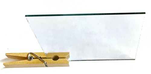
Figure 8. Clothespins or binder clips can be used to make the mirrors stand up.
- Prompt student groups to brainstorm how they could use the mirrors and aluminum foil to steer the light beam to the target. Remind them that they want to find the shortest light path through the maze, and they want to use the least number of reflective surfaces. Note: The mirrors will reflect the light better than the aluminum foil as the wrinkles in the foil lead to a more diffuse reflection. During their investigations, let students discover that not all reflective materials reflect light in the same way.
- Each student within a group should come up with one design solution. Have them draw their mirror setup and the predicted light path based on the law of reflection on their worksheet.
- Within each group, students should compare their designs and decide which solution they will build. They can also pick the best parts of different designs and combine them to make a single, better design. Have students re-draw their selected mirror setup, including its predicted light path, on the worksheet.
- Each group should build their prototype solution using the setup that they have proposed in their chosen design. Then have students use the flashlight and test their design. To test their design, students should observe if the light beam covers the whole bullseye target and they should also measure the length of their light path with a ruler or yardstick. Alternatively, they can use a string to measure the length of the light path in their setup. Based on their results, they should discuss:
What works well in our design?What does not work well in our design?How can our design be improved?Can we reduce the number of reflective surfaces in our design?Can we shorten the path of light in our design?
- Make students aware that a first design solution is often not the best solution. Each design solution needs to be tested, and then modified on the basis of the test results.
- Based on their results, have student groups decide how they want to improve their designs. Even if they have found a solution that redirects the light to the target, ask them to think about if they can use fewer reflective surfaces or if they can make the path of light shorter in their design. Each group should go through at least two design iterations and record their observations on their worksheets.
- Give students a total of 30 minutes to come up with and finalize their design.
/-/https/www.sciencebuddies.org/cdn/Files/16586/6/standing-mirror.jpg)
For groups who are done early, ask them if a second, equally good solution can be found. If not, ask them to see if a solution with a shorter light path, but using one extra mirror, is possible.
Reflect (30 minutes)
- Once all students have finalized their designs, gather all groups. Then walk from workstation to workstation and ask each group to present the design solution they came up with. Let students explain and have them demonstrate how the light beam travels through their maze and check the design requirements for each group. You can, for example, use a table (see Table 1) to check off if the design requirements have been met. Also, make a note of how many materials were used to guide the light beam onto the target and how long the light path is. This might also be a good opportunity to discuss how the mirror and aluminum foil reflected the light in a different way. Mention how materials that do not have a smooth surface reflect light in a diffuse way as bumps on their surfaces cause light to reflect in many directions (Figure 3). Questions you can ask each group are:
What was easy or difficult about guiding the light beam to the target?Why did you choose this position for your mirror or aluminum foil?What differences did you notice between the two reflective materials (mirror and aluminum foil)?
| Design Requirements | Student Groups | ||||
|---|---|---|---|---|---|
| 1 | 2 | 3 | 4 | 5 | |
| Does light beam start in entrance window, at a 90-degree angle with the border line? | Yes | ||||
| Does light beam cover the whole bullseye target? | Yes | ||||
| Are all materials within the 25" x 30" boundary? | Yes | ||||
| What is the length of the light path [in inches]? | 53 | ||||
| Number of materials* used for light redirection | 4 | ||||
Table 1. Table to check the design requirements for each group's design. The first column has been filled in as an example.
- At the end of the mirror maze "show and tell,"
have students discuss and compare their different designs.
Did groups come up with similar designs?How are the designs similar or different?Did any groups have a unique design that no one else made?Which design used the most or the fewest materials to redirect the light?
- Present the class with the results table (Table 1) that you made for each group design. Review the table together as a class and nominate the winning team(s) of the challenge. If no group came up with a design with three mirrors, ask if designs could be combined to form an even better design.
- Wrap up the lesson by coming back to the video that you showed in the beginning. Ask students if they can now answer these questions based on what they have learned about the law of reflection.
How do you think the townspeople knew where to place the mirrors on the mountain?How could they be sure the reflected sunlight would hit the city square and not another target?Why do you think the mirrors are built so they can track the Sun?Encourage students to use their newly gained vocabulary to explain how the law of reflection can be used to determine the positioning of the mirrors on the mountain based on the position of the Sun, and thus determine the incident angle of the incoming light. They can use the same arguments to explain why tracking the Sun is necessary to keep the reflected light beam centered on the town square. As the Sun moves through the sky, the mirrors have to be adjusted to compensate for the change in the angle of incidence.
Assess
You can use this quiz to assess student learning after the activity:
- Online quiz, assignable in any LMS
- Quiz (pdf) and answer key (PDF)
Make Career Connections
Discussing or reading about these careers can help students make important connections between the in-class lesson and STEM job opportunities in the real world.
/-/https/careerdiscovery.sciencebuddies.org/cdn/Files/1609/17/iStock-1007669236.jpg)

/-/https/careerdiscovery.sciencebuddies.org/cdn/Files/1789/24/ill_11.png)
Lesson Plan Variations
- In addition to checking if the light hits the target, you can also measure how much light hits the target. With each redirection there is the possibility of light being scattered and thus being lost. This means the light intensity gradually decreases on the way through the maze. To measure how much light is lost, you can use a light sensor to measure light intensity. There are many apps available that are able to use a mobile phone's camera to measure light intensity (such as the Arduino Science Journal). As a reference, you will need to measure the light intensity of the light that hits the target directly in a straight line without any obstacles or redirection and from the same distance as the entrance window to the target. Then you can measure the light intensity of the light that hits the target after steering it through the maze. The difference is the light intensity that has been lost in the mirror maze.
- Allow students to change the angle of the incoming light in the entrance window of their maze. What changes in their design if they can move the flashlight?
- Have students come up with their own mirror maze.
- Make a mirror maze worksheet and let students draw the predicted path of light through the mirror maze.
/-/https/img.youtube.com/vi/A0FuVMHMyZE/0.jpg)
/-/https/img.youtube.com/vi/Obyqku2vWc4/0.jpg)
/-/https/img.youtube.com/vi/jGvnRxCpRRs/0.jpg)