The Math Behind Circuits
Summary
/-/https/www.sciencebuddies.org/cdn/Files/18749/10/tech-interactive.png)
Overview
In this math-based lesson, students explore different types of circuits and make calculations to gain practical skills in building, visualizing, and understanding circuits.
Learning Objectives
Students will:
- Create circuits and draw circuit diagrams.
- Explore how voltage works in parallel and series circuits.
- Make calculations of voltage and milliamp hours.
NGSS Alignment
This lesson helps students prepare for these Next Generation Science Standards Performance Expectations:- Grade 4: 4-PS3-2: Make observations to provide evidence that energy can be transferred from place to place by sound, light, heat and electric currents.
- Science and Engineering Practices: Planning and Carrying Out Investigations, Using Mathematics and Computational Thinking
- Cross Cutting Concept: Energy and Matter, Systems and System Models
Common Core State Standards for Mathematics
- Grade 4: 4.OA.1 Use the four operations with whole numbers to solve problems.
- Grade 4: 4.MD.2 Use the four operations to solve word problems involving distances, intervals of time, liquid volumes, masses of objects, and money, including problems involving simple fractions or decimals, and problems that require expressing measurements given in a larger unit in terms of a smaller unit. Represent measurement quantities using diagrams such as number line diagrams that feature a measurement scale.
- Grade 6: 6.EE.A.2.C Expressions and Equations: Evaluate expressions at specific values of their variables.
- Grade 7: 7.NS.3 Solve real-world and mathematical problems involving the four operations with rational numbers.
Common Core State Standards for English Language Arts
- Grades 6-8: RST.6-8.7 Integrate quantitative or technical information expressed in words in a text with a version of that information expressed visually (e.g., in a flowchart, diagram, model, graph, or table).
Materials
| Circuits (1 set per team) | Diagrams and Calculations (1 set per student) |
|---|---|
|
|
Tip: Don't use tape or glue. This allows for faster iteration, more reuse of materials, and less mess.
Background Information for Teachers
Vocabulary
- Circuit: A complete circular path that electricity flows through.
- Current: A flow of charged particles, such as electrons or ions, moving through an electrical conductor or space.
- Diagram: A graphical representation of an electrical circuit.
- Milliamp: A unit of measurement for an electric current flowing through an electrical conductor.
- Parallel circuit: A circuit where current is flowing in multiple branches at one time.
- Power: A source or means of supplying energy.
- Series circuit: A circuit where current is flowing in only one closed loop at a time.
- Schematic: A diagram using abstract, graphic symbols used by engineers to communicate information.
- Voltage: Electric potential or potential difference expressed in volts.
- "Circuit Symbols and Circuit Diagrams," The Physics Classroom
- "What is a Series-Parallel Circuit," AllAboutCircuits.com, EETech Media
For more lesson plans, videos and other facilitation resources see thetech.org/resources.
Prep Work
Lesson Preparation
- Collect, organize, and set up materials.
- Print the Circuit Scenarios Handout for Session 2 (one per team).
- Build a couple of circuits yourself with other educators or kids you know. This will give you practice with the materials and tools to help anticipate student questions.
If you took the Simplicity of Electricity lab at The Tech Interactive, plan to have students recall their experience at the beginning of the lesson.
Looking for additional design challenges? Try The Tech Challenge at The Tech Interactive. This lesson was developed to prepare students for the 2019 Tech Challenge: No Roads, No Problems, presented by Dell.
Lesson Instructions
| Session 1: Building Circuits | 60 min total |
| Teams will practice building series and parallel circuits, interpreting schematics, and diagramming what they built. | |
| Session 2: Circuit Calculations | 60 min total |
| Teams will explore practical circuit calculations and apply these to a series of scenarios. | |
Session 1
| Session One Outline | 60 min total |
|---|---|
| Introducing Circuitry Engineering | 5 min |
| Circuit Exploration | 20 min |
| Series and Parallel Circuits | 15 min |
| Diagramming and Building Circuits | 15 min |
| Wrap Up | 5 min |
Introducing Circuitry Engineering (5 min)
- Activate prior knowledge by exploring what learners already know about electrical power. Guiding Questions could include:
- What are some items that you use that need electricity for power?
- What are some things these items have in common (i.e., a switch or another way to activate the device)?
- Can you think of any items that have multiple lights sharing a single power source (i.e., a string of holiday lights)?
- Let learners know that today they are going to investigate the inner workings of electrical items by building circuits.
Circuit Exploration (20 min)
- Divide learners into teams of two to four. Give each team one set of circuit materials.
- Introduce the Circuit Exploration Challenges and give teams 10 minutes to explore the circuit materials and complete as many of the challenges as they can.
| Circuit Exploration Challenges | |
|---|---|
| Challenge 1 | Light up one bulb. |
| Challenge 2 | Light up one bulb with the fewest materials possible. |
| Challenge 3 | Light up two bulbs in two different ways. |
| Challenge 4 | Light up three bulbs in two different ways. |
- While teams are building circuits, walk around the room, troubleshoot, and support teams as needed. If teams are stuck on how to proceed, try asking open-ended questions, such as:
- What have you tried?
- What do you think your circuit needs?
- What might be preventing the electricity from flowing through your circuit? Is everything connected?
-
- Take a quick poll to assess where teams are in the challenges. Let them know it is fine if they have not completed Challenges 3 and 4 as they will be exploring them more in the next section.
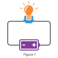
- Ask teams to share their solutions for Challenge 2. Confirm that the way to light the bulb using the fewest components is with a power source, two wires, and a bulb.
- Ask for a volunteer to draw their circuit on the board.
- Trace the path the electricity is taking through the circuit components to show that everything is connected to something else (see Fig. 1 to the right).
-
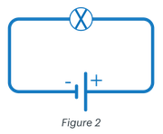
- Draw the same circuit with schematics (See Fig. 2 to the right).
- Ask students: Why might a schematic diagram be preferable to a drawing?
- Discuss how diagrams are used to communicate information about the path of a circuit regardless of the language spoken by the engineer, allowing them to work with other engineers anywhere in the world.
/-/https/www.sciencebuddies.org/cdn/Files/19775/6/math-circuits-3-lightbulb.png)
/-/https/www.sciencebuddies.org/cdn/Files/19776/6/math-circuits-4-schematic.png)
Series and Parallel Circuits (15 min)
- Pass out paper and pencils. Encourage students to troubleshoot their circuits by drawing a diagram or creating a schematic.
- Give teams five more minutes to explore Challenge 3, light up 2 bulbs in two different ways. Bring the class back together when the time is up.
- Ask for a volunteer to share one of their two-bulb circuits by drawing a diagram on the board. Then ask a volunteer from a different group to share a different example of a two-bulb circuit.
- Label the appropriate diagrams as series circuit and parallel circuit. Confirm that all of the teams have built both kinds of circuits.
- Ask students: What differences did you notice between the two types of circuits during your exploration? Responses may include:
- The bulbs are brighter in the parallel circuit than in the series circuit.
- This is because there is more voltage (and therefore more current) flowing to the bulbs in the parallel circuit.
- The series circuit required three wires while the parallel circuit required four.
- The bulbs are brighter in the parallel circuit than in the series circuit.
- Explain the difference between series and parallel circuits.
| Series Circuit | Parallel Circuit |
/-/https/www.sciencebuddies.org/cdn/Files/19777/6/math-circuits-5-series-circuit.png) |
/-/https/www.sciencebuddies.org/cdn/Files/19778/6/math-circuits-11-parallel-circuit.png) |
|
There are different paths for the electricity to take, so the current splits depending on the resistance of each path. The total current is the sum of the currents through each component. The voltage across each of the paths is the same. |
Diagramming and Building Circuits (15 min)
- Draw a diagram of three bulbs in series circuits and three bulbs in parallel circuits on the board.
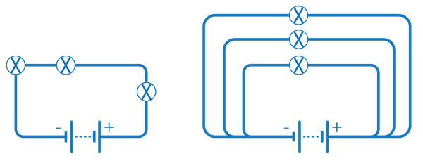
- Teams will spend the next 15 minutes exploring Challenge 4, building and diagramming how to light up 3 bulbs in two different ways.
- Ask teams to show you once they have completed each one.
- Have teams draw a diagram of a three- (or more) bulb circuit they have built.
- If teams finish building and diagramming their circuits early, have them trade diagrams with another team and try to build their circuit.
- Supply teams with more wires and bulbs as needed.
- Optional: Pass out switches, motors, fans or buzzers and challenge teams to add them into their circuits. If using fans teams will need to connect them to a motor first.
/-/https/www.sciencebuddies.org/cdn/Files/19779/6/math-circuits-7-schematic-diagrams.png)
Debrief (5 min)
- Lead a short debrief with some of these questions:
- What did you find challenging about building circuits?
- How did drawing the diagrams help your team understand how to build the circuits?
- How do schematics help engineers communicate their ideas?
Key for Component Symbols
/-/https/www.sciencebuddies.org/cdn/Files/19780/6/math-circuits-9-key-components.png)
Session 2
| Session Two Outline | 60 min total |
|---|---|
| Introducing Circuit Calculations | 5 min |
| Practical Circuit Questions | 35 min |
| Practice Calculations | 10 min |
| Sharing Solutions | 10 min |
Introducing Circuit Calculations (5 min)
- Ask for volunteers to briefly review what they learned about building circuits in the previous session.
- Let students know that today they will be practicing some circuit calculations. Calculations will help them determine what is happening with their circuit, including the amount of current, voltage and energy.
/-/https/www.sciencebuddies.org/cdn/Files/19787/6/math-circuits10-triangle.png)
If you are new to teaching circuit calculations, we recommend reviewing Ohm's Law prior to this lesson. Ohm's Law states that current through a conductor between two points is directly proportional to the voltage across the two points.
Practical Circuit Questions (35 min)
- Use the tables below to help students work through a series of calculations needed to understand the circuits they explored in the last session.
| What is the total voltage of the batteries? | |||
|---|---|---|---|
| Diagram | Question | Answer | |
| Series Circuits Calculate the voltage in a series by adding the voltage in the batteries together. |
/-/https/www.sciencebuddies.org/cdn/Files/19788/6/math-circuits-12.png) |
1.5V + 1.5V = X | Total voltage = 3V |
| Parallel Circuits Calculate the total voltage supplied in a parallel circuit by adding the voltage of the batteries in one branch together. |
/-/https/www.sciencebuddies.org/cdn/Files/19789/6/math-circuits-13.png) |
1 branch = 1.5V | Total voltage = 1.5V |
/-/https/www.sciencebuddies.org/cdn/Files/19790/6/math-circuits-14.png) |
1 branch = 2 series batteries 1.5V + 1.5V = X | Total voltage = 3V | |
One battery in parallel with two will ruin your single battery and your circuit! If you are putting your batteries in parallel, make sure you have the same number of 1.5V batteries in each branch of your circuit.
- Once students understand the total voltage of the circuits they explored, have them consider:
If you can use two 1.5V batteries in series to supply 3V, why would you use two pairs of two 1.5V batteries (four batteries total) to supply 3V to your circuit?
- Remind them that, in addition to voltage, when looking at electrical components we also want to know how long they will last.
- Use the table below to work through these calculations with students.
| How long will my batteries last? | ||
|---|---|---|
|
Calculate the hours that your battery will last using mAh/I (milliamp hours of your batteries divided by the current in milliamps).
Example: If your current is X milliamps and you have a AAA battery, then 750 mAh/X milliamps = Y hours. Let's assume the current in our circuit is 300 milliamps and use that to calculate how long each of these batteries will last. | ||
| Battery type | mAh (milliamp hours) | Hours at 300 milliamps |
| AAA | 750 mAh | 2.5 |
| AA | 2,800 mAh | 9.3 |
| C | 8,200 mAh | 27.3 |
| D | 21,000 mAh | 70 |
- Ask students to determine how long two AAA batteries will last in series versus parallel.
- In series, the battery voltage is constant across the entire circuit, so two batteries give the same mAh as one.
- Ex: Two AAA batteries in a series = 750 mAh at 3V
- In parallel, the battery voltage is constant across all the circuit branches, so they would need to add the mAh for each battery.
- Ex: Two AAA batteries in parallel = 1,500 mAh at 1.5V
- In series, the battery voltage is constant across the entire circuit, so two batteries give the same mAh as one.
- Revisit the question above: Based on our calculations, why would you use two pairs of two 1.5V batteries (four batteries total) to supply 3V to your circuit?
- Two pairs of two 1.5V batteries in parallel will supply 3V to your circuit, but will last longer.
Practice Calculations (10 min)
- Have students get back into their teams. Let them know that they are going to spend the next 10 minutes applying what they have learned about calculations to a few scenarios.
- Pass out the Circuit Scenarios Handout and pencils.
- Give teams 10 minutes to come up with solutions to the scenarios.
- Encourage them to use diagrams and calculations to think through their ideas.
- They should do this for both series and parallel battery connections.
- Bring the whole group back together when the time is up.
| Scenarios | Circuit Scenario Questions | Answers |
| Scenario 1 | How could you light up three 1V light bulbs using three 1.5V batteries?
Tip: The total voltage of the batteries needs to equal the total voltage of all the devices in the circuit in order for everything to light up. | All lightbulbs will light up when the batteries are in series:
1.5 V + 1.5V + 1.5 V = 4.5 V 1 V + 1 V + 1 V = 3 VIn parallel, there is not enough voltage to light up all the lightbulbs: 1 branch = 1.5 V 1 V + 1 V + 1 V = 3 V |
| Scenario 2 | Which will last longer to power a circuit, two AA batteries in series or 4 AAA batteries in parallel? | Two AA in series is 2,800 mAh because it's the equivalent of only one battery.
4 AAA in parallel is 3,000 mAh because it's 4 batteries times the mAh, so the 4 AAA will last longer. |
- If learners are experimenting with motors and fans, you may want to calculate the power in your circuit using the calculation V * I (or I^2 R). so you don't overload your component.
- Power = Voltage * Current = V * I
- Power is in units of watts
- We also recommend looking for a rating on your component (usually in volts) to make sure it is rated for the voltage you are supplying.
- If the motors are rated for a lower voltage than you are supplying, you will need resistors to make the circuit work. We recommend avoiding this unless you are experienced at working with resistors.
Sharing Solutions (10 min)
- Ask for teams to share their solutions for each of the scenarios.
- Encourage them to share their thought process and calculations.
- Sharing questions can include:
- What process did you use to make that decision?
- How did you use the calculations and math to determine your answer?
- Where do you think these types of calculations get used in the real world?
- Have students explore building circuits with an online simulator like Circuit Diagram Editor.
/-/https/img.youtube.com/vi/r0UDLuV6058/0.jpg)
/-/https/img.youtube.com/vi/mhPrxoMnVds/0.jpg)
/-/https/img.youtube.com/vi/MIS-r5K_9WE/0.jpg)