Abstract
This is an interesting project that explores which geometrical shapes make the strongest bridge truss structures. It is a good introduction to the engineering design process. You'll design three different trusses, and use online simulation software to analyze the distribution of load-bearing forces in each design. Then you'll build and test prototypes of each design.
Summary
Excellent computer skills, high school physics course
Readily available
Use caution with sharp tools when cutting wooden parts to size. Adult supervision recommended for bridge-testing phase.
Jenny L. Cooper, for using water as calibrated weight
Whiting School of Engineering at Johns Hopkins University, for the Bridge Designer simulation software
Elmer's® is a registered trademark of Elmer's Products, Inc.
/-/https/www.sciencebuddies.org/cdn/Files/2141/8/CE_img005.jpg)
Objective
The objective of this experiment is to measure the relative strength of bridge truss designs based on three different shapes: equilateral triangle, right isosceles triangle, and 30-60-90 triangle. The trusses will have equal span lengths, and will be built with the same material and construction techniques.
Introduction
When planning a particular bridge, an engineering team follows a design process. You can follow the same process (see Bibliography) as you work through this project. There are several different basic designs for bridges: beam, cantilever beam, arch, suspension and cable stay. Some bridges combine elements of multiple types. An engineer considers the design criteria in order to select the most appropriate type for a specific site and use profile.
For this project, you will be designing and building a bridge truss, which is a type of beam. A well-designed truss has a high strength-to-weight ratio. The braces of a truss form a frame which can effectively transfer load forces throughout the structure. As part of the design process, you will learn how to use an online simulation program to show how load forces are distributed through the bridge truss you design. Before you test your prototype trusses, try to use the information from the simulation program to predict which of your designs will be the strongest.
Terms and Concepts
- Basic bridge types: beam, cantilever beam, arch, suspension and cable stay
- Span
- Bridge truss
- Compression forces
- Tension forces
- Strength-to-weight ratio
- The physics underlying bridge design are Newton's classical laws of mechanics. Your background research should enable you to explain how Newton's second and third laws (F = m × a, and "for every action there is an equal, and opposite, reaction") apply to the analysis of load bearing. You may not be able to do the calculations for a complicated truss by yourself, but you should be able to explain the results produced by the Bridge Designer program (see Bibliography) for a simple truss design, such as the one used in this project.
- Before you test your prototype trusses, try to predict which design will be the strongest by using your simulation results for the different truss designs.
Bibliography
- Check out the Science Buddies Engineering Design Project Guide. There are parallels between the methods used by scientists and by engineers, but there are important difference too. This guide has helpful information on the engineering method.
- Bridge Designer online simulation software. The Whiting School of Engineering at Johns Hopkins University has an online Bridge Designer program that you can use to design a bridge truss. You can then add load to your design, and the program will calculate the tension and compression forces on the component parts. You can use it as part of your design process, for testing out ideas and hunches before you build.
https://ei.jhu.edu/truss-simulator/ - This link has results of an annual balsa bridge building contest for physics students at the Notre Dame Regional High School in Vancouver, B.C., Canada. There are pictures of winning bridges and long list of links to bridge-engineering-related sites. There's also a cool animated GIF of the Tacoma Narrows suspension bridge resonating before it collapsed.
http://www.balsabridge.com/
Materials and Equipment
- Computer with internet access for Bridge Designer simulations
- Protractor, ruler, paper and pencil for making full-scale drawings of your truss designs
- Wax paper to cover your design as you build the truss on top of it
- Two layers of flat corrugated cardboard to put underneath your design
- Common pins to hold pieces in place as the glue dries
- Single-edge razor blade or hobby knife for cutting parts to size
- Enough building material to construct 9 individual trusses (3 of each type)
For building material, balsa wood (available at your local hobby store) and Elmer's® Wood Glue or Elmer's® Glue—all are good choices. Other possibilities are spaghetti, toothpicks, wooden coffee stirrers, or popsicle sticks. - Scale to measure the weight of the trusses, such as the digital pocket scale available at Amazon.com
- Supports for mounting the model truss in order to test weight-bearing capacity
- Wire to hang weights from truss
- Calibrated weights, or a container for water (see Experimental Procedure, step 6)
Disclaimer: Science Buddies participates in affiliate programs with Home Science Tools®, Amazon.com, Carolina Biological, and Jameco Electronics. Proceeds from the affiliate programs help support Science Buddies, a 501(c)(3) public charity, and keep our resources free for everyone. Our top priority is student learning. If you have any comments (positive or negative) related to purchases you've made for science projects from recommendations on our site, please let us know. Write to us at [email protected].
Experimental Procedure
- Do your background research on the engineering design process and the physics of bridge design.
- Use the Bridge Designer online simulation program from the Whiting School of Engineering at Johns Hopkins University to see how load forces are distributed through the structure of each truss design. If you are following this project exactly, you will be simulating three separate trusses, based on the following triangles:
- equilateral (60-60-60),
- right isosceles (45-45-90), and
- 30-60-90.
- The Bridge Designer software has instructions, and is fairly simple to use. Here are some screenshots of the program for reference, and an outline of the procedure you will follow. Note: the website has been updated and the interface may no longer look exactly like the screenshots below, but the buttons and functionality should remain the same.
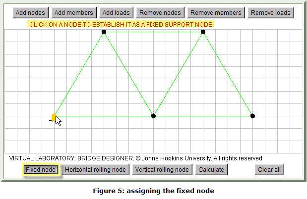
- This is the Bridge Designer interface. The buttons across the top allow you to add or remove nodes (connection points), members and loads. Just below the buttons is a single line of instructions for the current mode. You construct your truss design on the "graph paper, using the grid lines to get the angles you want. You must assign two special nodes: a fixed support node, and a horizontal rolling node. Be careful with the "Clear all" button, it erases everything instantly.
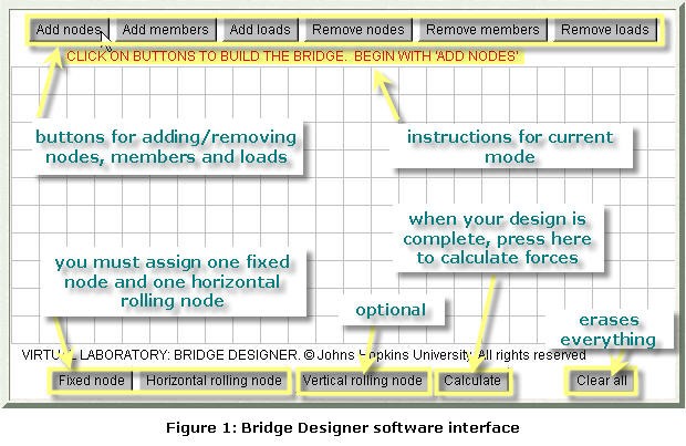
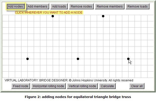
- To get started, click the "Add nodes" button, then click where you want the nodes placed. If you make a mistake, use the "Remove nodes" button to erase nodes one at a time.
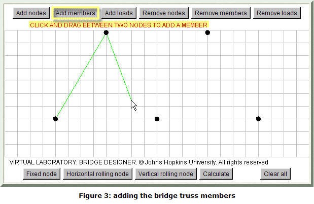
- When your nodes are in place, complete the structure of the truss using the "Add members" button. Click and drag between nodes to create a brace.
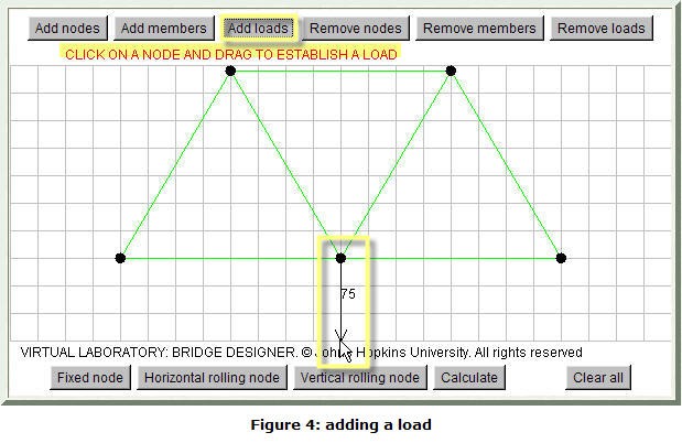
- Use the "Add loads" button to apply a force to your truss. Click on a node and drag. The magnitude of the force increases as you drag further (indicated by number). The direction of the force is indicated by the arrow.
- Use the "Fixed node" and "Horizontal rolling node" buttons to anchor your truss.
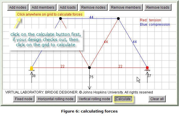
- Click on the calculate button to have the program analyze the forces. If everything checks out, you'll see the instruction line shown here. Click anywhere on the graph, and the results will appear. Members under tension are colored red; members under compression are colored blue. Remember to save your results by printing them out, or jotting them down on a sketch.
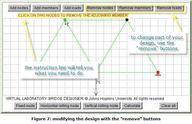
- To change your design, use the "Remove" buttons to remove individual components. The instruction line will tell you what to do. Remember to keep the span constant for the different designs.
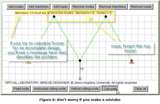
- If you make a mistake, don't worry. For example, here the design violates one of the constraints imposed by the simulation program. When you try to calculate the forces, you get an error message on the instruction line. Just change the design so that the members and nodes satisfy the constraint, and try again.
- This is the Bridge Designer interface. The buttons across the top allow you to add or remove nodes (connection points), members and loads. Just below the buttons is a single line of instructions for the current mode. You construct your truss design on the "graph paper, using the grid lines to get the angles you want. You must assign two special nodes: a fixed support node, and a horizontal rolling node. Be careful with the "Clear all" button, it erases everything instantly.
- The next step is to build your prototype trusses. Use the same material and construction methods for all three designs. It is best to build three separate examples of each design, to make sure your test results are reliable. Here is a step-by-step procedure for the building process:
- Start by making a full-scale, side-view drawing of each of the three trusses. You will use these drawings
- to determine how much material you need for each truss (get 10% extra, in case of mistakes!), and
- as a template for actually building the trusses (if you've ever built a balsa wood airplane, you'll be familiar with this technique).
- As you make your drawing, and as you do the actual building, pay special attention to all of the connections where the braces come together (see Bibliography).
- A good way to build the trusses is right on top of the scale drawing. You can lay the pieces of material right over the drawing to make your cuts so that you get the angles correct. Cover the drawing with wax paper, and put two flat pieces of corrugated cardboard underneath it. You'll be able to see your plan through the wax paper, and it will prevent your truss from sticking to the plan. You can hold the pieces in place as the glue dries by using common pins, placing them on either side of a piece to hold it in place. Work methodically, and take your time.
- Let the glue dry hard before trying to remove the truss from the plan. (If you want to build all 9 trusses at the same time, make 2 extra copies of each plan. You'll also need corrugated cardboard and wax paper for each truss.)
- When the glue is fully dry, remove the pins, and carefully press the wax paper away as you lift the truss off the plan. Check all of your joints, and add more glue if needed. Follow the same procedure for all of the trusses.
- Start by making a full-scale, side-view drawing of each of the three trusses. You will use these drawings
- Weigh each truss and record the weight. If you don't have access to a scale, take them to the post office. Often there is a self-service counter with a scale, or ask a clerk at the counter to help you.
- The next step is to test the strength of each truss. You will need to support both ends of the truss, and hang calibrated weights from the center of the span, adding progressively more weight (in 0.25 kg or 0.5 kg steps) until the truss fails. One way to do this is by hanging a container from the truss, and gradually filling it with water. Keep track of how much water you add each time. Water weighs 1 g per ml, so if you want 0.25 kg steps, add 250 ml, for 0.5 kg steps, add 500 ml. Don't forget to include the weight of the empty container in your total. If you set things up so that the (flat-bottomed!) container is hanging just above the floor, you shouldn't have a problem with spilling when the truss eventually gives out. For each truss, record the maximum load successfully carried (i.e., the step before the truss failed).
- Analyze your results. Here are some suggestions to get you started.
- Calculate the strength-to-weight ratio for each truss, and compare the average ratio for each design. Did your results agree with your prediction from the simulation? Why, or why not?
- Perform a Failure Analysis on each truss. Where did the structure fail? Did all of the trusses fail in the same way? Did all of the trusses with the same design fail in the same way? Study the force diagrams from the Bridge Designer simulation program. Do they give you any insight into the failure?
- Can you think of ways to improve your designs? (Try them out! Remember: iteration is a critical part of the design process!)
- Prepare your display (you can find tips on Science Buddies "How to Do a Science Fair Project" pages). Remember to include your simulation results. You may want to include pictures (or even examples) of the broken trusses to illustrate your analysis.
/-/https/www.sciencebuddies.org/cdn/Files/2138/8/CE_img002.jpg)
/-/https/www.sciencebuddies.org/cdn/Files/2139/8/CE_img003.jpg)
/-/https/www.sciencebuddies.org/cdn/Files/2140/8/CE_img004.jpg)
/-/https/www.sciencebuddies.org/cdn/Files/2141/8/CE_img005.jpg)
/-/https/www.sciencebuddies.org/cdn/Files/2142/8/CE_img006.jpg)
/-/https/www.sciencebuddies.org/cdn/Files/2143/8/CE_img007.jpg)
/-/https/www.sciencebuddies.org/cdn/Files/2144/8/CE_img008.jpg)
/-/https/www.sciencebuddies.org/cdn/Files/2145/8/CE_img009.jpg)
Ask an Expert
Global Goals
The United Nations Sustainable Development Goals (UNSDGs) are a blueprint to achieve a better and more sustainable future for all.
/-/https/www.sciencebuddies.org/cdn/Files/19752/5/E-WEB-Goal-09.png)
Variations
- Develop your own truss design and follow the steps in this project with it. Some ideas to get you started:
- use polygons other than triangles
- try to determine if additional cross braces improve the strength-to-weight ratio
- Stick with a single design, and investigate the relative strength of trusses built with different construction techniques. How can you make the strongest joints?
Careers
If you like this project, you might enjoy exploring these related careers:
/-/https/careerdiscovery.sciencebuddies.org/cdn/Files/1844/17/iStock-1036354066.jpg)
/-/https/careerdiscovery.sciencebuddies.org/cdn/Files/1133/17/pexels-photo-3862135.jpg)
/-/https/careerdiscovery.sciencebuddies.org/cdn/Files/1074/17/iStock-1176843661.jpg)
/-/https/careerdiscovery.sciencebuddies.org/cdn/Files/1125/17/pexels-photo-3862390.jpg)

/-/https/img.youtube.com/vi/xUmq8TUqt8c/0.jpg)
/-/https/img.youtube.com/vi/6fx0PEx0g5k/0.jpg)
/-/https/img.youtube.com/vi/cHsBr9v2YBw/0.jpg)