Abstract
If you want to get your friend's attention at a crowded sporting event with lots of people cheering, you need to shout. If you're trying to do the same thing in a quiet library, a whisper works. The detection limit for each of our senses depends on the amount of "background" stimulation that is already present. This project uses an LED control circuit to investigate detection of changes in light levels.Summary
/-/https/www.sciencebuddies.org/cdn/Files/2896/3/Elec_img099.jpg)
Objective
The goal of this project is to compare linear vs. logarithmic potentiometers for controlling signals that people sense (e.g., brightness of a light, or loudness of a sound).Introduction
Our five senses (sight, hearing, touch, taste, and smell) give us information about the environment around us. Our ability to detect small changes in these sensations (the "just noticeable difference"), is proportional to the original intensity of the sensation. For example, if you are in a very quiet room, you can hear a whisper. A second person whispering could also be heard: the added sound would be significant in relation to the existing sound level. On the other hand, if you're at a basketball game with a lot of people cheering, you would not be able to hear someone whispering two rows down, because now the added sound is insignificant in relation to the existing sound level. In other words, as sounds get louder, there needs to be a bigger change in intensity in order to detect it.
The same holds true for other sensations. On a dark night, with your eyes adapted to low light levels, you can see a single candle a mile away. In broad daylight, the candle has to be much closer before you can distinguish it, because the existing light level in daylight is so much greater.
The mathematical description of this phenomenon is called Stevens' Power Law (Staff, 2004). In words, Steven's Power Law says that the perceived sensation, R (loudness of a sound, brightness of a light), is an exponential function of the actual level of the stimulus, S, (measured sound level or brightness). In equation form, it looks like this:
/-/https/www.sciencebuddies.org/cdn/Files/2887/3/Elec_img101.jpg)
S0 is the threshold, or lowest detectable level, of the sensation, and k is a proportionality constant. The value of the exponent, α, depends on the particular sensation. Taking the logarithm of both sides of the equation, we get:
/-/https/www.sciencebuddies.org/cdn/Files/2888/3/Elec_img102.jpg)
So on a double-log plot, the perceived response, R, to a stimulus, S, will be a straight line, with slope equal to α (the exponent in the original equation) and y-intercept equal to log k. In this project, you will use an LED with a simple control circuit to investigate how changes in light intensity are sensed. Before getting started, you'll need some background information on how LEDs work.
An LED (light-emitting diode) is a special kind of diode that produces light (see Figure 1).
/-/https/www.sciencebuddies.org/cdn/Files/2883/5/Elec_img082.jpg)
Figure 1. A red LED (top). The longer lead is the anode (+) and the shorter lead is the cathode (−). In the schematic symbol for an LED (bottom), the anode is on the left and the cathode is on the right (Hewes, 2006).
When current flows through the diode in the forward direction, some of the current is converted into light of a specific color (i.e., wavelength). The color of the light depends on the material from which the semiconductor is made. LEDs are available in many different colors.
As the current through the LED increases, the brightness also increases. Typically, the recommended current for an LED is 20 mA or less. Above this value, the lifetime of the LED will be decreased significantly. Far above this value, the LED will fail catastrophically, like a flashbulb.
To keep the LED current at a reasonable level, LEDs are typically connected in series with a current-limiting resistor, as shown in Figure 2.
/-/https/www.sciencebuddies.org/cdn/Files/2884/5/Elec_img083.gif)
Figure 2. Schematic diagram of an LED in series with a 1kΩ resistor (Hewes, 2006).
The voltage drop across an LED is about 2 V (except for blue or white LEDs, where the voltage drop is about 4 V). In the circuit in Figure 2, the voltage drop across the resistor will be 9 − 2 = 7 V. Using Ohm's law, the current, I, through the resistor will be V/R = 7 V/1kΩ = 7 mA.
Figure 3 shows you how to use Ohm's Law to calculate what size resistor you need to limit the current through the LED to the desired value. The voltage drop across the resistor will equal the supply voltage minus the voltage drop across the LED (or, VS − VL). You can then use Ohm's Law to calculate the resistance, R, needed to produce a desired current, I:
So, if the supply voltage is +7 V, what resistor would you need for a 15 mA current? R = (7 − 2)/0.015 A = 333Ω. The closest standard resistor value would be 330 Ω. For more details, and a set of online calculators, see the LED references in the Bibliography section (Hewes, 2006; Ngineering, 2003).
/-/https/www.sciencebuddies.org/cdn/Files/2885/5/Elec_img084.gif)
A circuit diagram shows supply voltage from a battery being lost when passing through an LED. The desired current flowing into an LED, supply voltage and voltage lost can be used to calculate the correct limiting resistor.
Figure 3. Schematic diagram showing how to use Ohm's Law to calculate the correct value for the current-limiting resistor (Hewes, 2006).
For this project, we'd like to vary the output of an LED over a continuous range. Obviously, it would be a major inconvenience if we had to keep changing the current-limiting resistor for each LED! The circuit shown in Figure 4 is a different approach to solving our problem.
/-/https/www.sciencebuddies.org/cdn/Files/2886/5/Elec_img091.gif)
Figure 4. This circuit uses an operational amplifier (op-amp) to control the current through an LED (Calvert, 2002).
The large triangle marked "LF411" in the center of the schematic is an operational amplifier, or op-amp, for short. An op-amp has two inputs and one output. (It also has positive and negative supply inputs, typically +/− 15 V, which are usually not shown in schematics.) In the schematic, the first input (marked +, and called the non-inverting input) is connected to a potentiometer. The second input (marked −, and called the inverting input) is connected to two circuit elements. It connects to the cathode of an LED, and to a 330 Ω resistor that connects to ground. The output of the op-amp is connected to the anode of that same LED. So the output of the op-amp is fed back to the inverting input. Op-amps are almost always used with some type of feedback.
What does the op-amp do? For a good basic understanding of how op-amps work in circuits, you just need to understand two simple rules (Horowitz and Hill, 1989, 177):
- "The output attempts to do whatever is necessary to make the voltage difference between the two inputs zero.
- "The inputs draw no current."
These rules are simplifications—for example, the inputs do draw some current. For the LF411 op-amp used in this project, 0.2 nA. You won't be able to measure that with your DMM! So these op-amp rules, as the authors state, are "good enough for almost everything you'll ever do," (Horowitz and Hill, 1989, 177).
What do the op-amp rules mean for our LED control circuit? Let's examine the inputs to the op-amp to figure it out. The potentiometer connected to the non-inverting input is a variable resistor. When wired as shown in the schematic (Figure 4), the output from the center lug of the potentiometer provides a voltage, ranging between 0 and +5 V, depending on how far the knob is turned. Simple enough. OK, what about the non-inverting input? This is the feedback connection from the output. So, by rule 1, the op-amp output should do whatever is necessary to make the voltage at the inverting input match the voltage we set with the potentiometer.
Let's consider three examples:- with the potentiometer knob all the way down (0 V),
- half-way up (+2.5 V), and
- all the way up (+5 V).
Example 1 is the easiest. With 0 V at the non-inverting input, there should be 0 V at the inverting input (rule 1), so the op-amp does nothing. No current flows through the LED.
With the potentiometer half-way up, the non-inverting input of the op-amp sees +2.5 V. How does the op-amp match that at the inverting input? It does it by passing current through the LED. How much current? Enough current so that the voltage at the inverting input equals +2.5 V. Where does the current go? The current flows to ground through the 330 Ω resistor (by rule 2, we know that the inputs draw no current, so the resistor is the only path to ground). By Ohm's Law, we have I = V/R = 2.5 V/330 Ω = 7.6 mA.
With the potentiometer all the way up, there is now +5 V at the non-inverting input. By the same analysis, we conclude that the current through the LED is now 15.2 mA. Perfect! The circuit has just the right range for a typical LED. The LF411 can supply 15 mA without a problem, so the behavior we expect from our op-amp rules is exactly the behavior that we get.
You can see from Ohm's Law that the LED current increases in direct proportion to the voltage from the potentiometer. Do some more calculations for more potentiometer settings to convince yourself that this is true. Then build the circuit and see how it actually performs.
The potentiometer in the op-amp circuit gives you a way to control the current, and thus the brightness, of the LED. It turns out that there are two types of potentiometers that you could use, linear or logarithmic (also called "linear taper" and "audio taper"). A linear potentiometer changes resistance in equal steps all around the dial. A logarithmic potentiometer changes resistance in successively larger steps as you advance the dial. Which one is a better match for controls related to human senses, like brightness or volume?
Terms and Concepts
To do this project, you should do research that enables you to understand the following terms and concepts:- Ohm's Law
- LED (light emitting diode)
- Voltage divider
- Integrated circuit
- Operational amplifier (op-amp)
- Weber-Fechner law
- Stevens's power law
- Logarithmic relationship
- Perception
Questions
- If you wanted the output current through the LED to max out at about 10 mA, what resistor would you use in place of the 330 Ω resistor in the LED control schematic?
- The voltage drop across a typical red LED is about 2 V (about 4 V for blue or white). What voltage would you expect to measure at the LF411 output (pin 6) when the potentiometer is half-way up (+2.5 V)? When the potentiometer is all the way up (+5 V)?
- (Advanced.) In the Experimental Procedure section (below), you'll see that we have you figure out the current through the LED by measuring the voltage across the 330 Ω resistor and then using Ohm's Law to calculate the current. Why can't you use the DMM in current mode to measure current through the LED directly?
Bibliography
- Science Buddies Staff. (n.d.). How to Use a Breadboard. Retrieved September 25, 2015.
These webpages have useful information on LEDs:
- Hewes, J. (n.d.). Light-Emitting Diodes (LEDs). The Electronics Club, Kelsey Park Sports College. Retrieved April 28, 2014.
- Ngineering. (2008). LED Calculators. Retrieved April 28, 2014.
Here is a page with an explanation of Ohm's law:
- Physics Department Staff. (n.d.) Ohm's Law. University of Guelph. Retrieved March 15, 2007.
The following are selected references on the Weber-Fechner law and Stevens' power law, both of which describe relationships between actual physical magnitude of a stimulus and the human perception of that stimulus:
- Nutter, F. (2010). Weber-Fechner Law. Encyclopedia of Research Design. Retrieved March 20, 2018.
- Wikipedia Contributors. (2007). Weber-Fechner law. Wikipedia: The Free Encyclopedia. Retrieved March 15, 2007.
- Wikipedia contributors. (2007). Stevens' power law. Wikipedia: The Free Encyclopedia. Retrieved March 15, 2007.
The following references are recommended for more-advanced students:
- Potentiometers:
- Wikipedia contributors. (2007). Potentiometers. Wikipedia: The Free Encyclopedia. Retrieved March 15, 2007.
- More-advanced students will benefit from reading this page, which is the original source for the LED control circuit used in this project:
Calvert, J.B. (2002, May 26). Electronics 45: Color. Retrieved March 15, 2007. - If you want to learn more about how op-amps work, this book is an excellent reference source, and we recommend it highly to those who are seriously interested in learning more about electronics:
Horowitz, P. and W. Hill. (1989). The Art of Electronics, Second Edition. Cambridge, UK: Cambridge University Press. - Here are some additional electronics books, recommended by Prof. James B. Calvert, Associate Professor Emeritus of Engineering, University of Denver:
- A. S. Sedra, A.S., and K.C. Smith. (1987). Microelectronic Circuits, Second Edition. New York, NY: Holt, Rinehart and Wilson.
- Jones, M.H. (1995). A Practical Introduction to Electronic Circuits, Third Edition. Cambridge, UK: Cambridge University Press.
- ARRL. (2006). The ARRL Handbook for Radio Communications. Newington, CT: American Radio Relay League. (Frequently updated with new editions. Title varies slightly; for example, older editions entitled The ARRL Handbook for the Radio Amateur. Newer edition preferred, but any would be suitable. Dr. Calvert remarks: "A good source of explanations, practical information and data, with emphasis on communications electronics.")
- Here is the technical data sheet for the LF411 op-amp (requires Adobe Acrobat Reader):
National Semiconductor. (2004). LF411: Low Offset, Low Drift JFET Input Operational Amplifier. Jameco Electronics. Retrieved March 15, 2007. - The data sheet for the light-to-voltage converter has complete specifications for these devices:
AMS (2016, Mary 30). TSL250R, TSL251R, TSL252R Light-To-Voltage Optical Sensors. Retrieved March 29, 2018.
Materials and Equipment
The following electronic parts are available from Jameco Electronics:- Powered breadboard, part #1942163. Note: powered breadboards are very expensive, but may be worth it if you plan on doing more electronics projects in the future. You could also check with a local university to see if you can have access to a powered breadboard in an electronics lab to do your experiment.
- Jumper wire kit, part #19290
- Digital multimeter (2). See our multimeter tutorial if you do not know how to use a multimeter.
- LF411Cn operational amplifier (2), part #23018. Note: this is a static-sensitive part. Only one is used in the project, but two are specified so that you'll have a spare in case of a mishap.
- High-output red LED (2), part #333526. Note: only one is used in the project, but it is a good idea to have at least one extra in case you accidentally burn out the LED.
- Linear taper 10 kΩ potentiometer, part #29082
- Audio taper 10 kΩ potentiometer, part #255426
- 330 Ω resistor (1 required, minimum order quanity is 10), part #690742
- 10 kΩ resistor (1 required, minimum order quanity is 10), part #691104
- Red knob, part #265051
- Green knob, part #265084
- Blue knob, part #265077
- Red #22AWG solid hook-up wire, part #36856
- Black #22AWG solid hook-up wire, part #36792
- Alligator clip test leads (10 pack), part #10444
- Heat shrink tubing, part #71871
You will also need the following materials:
- Light-to-voltage converter, Mouser Electronics part number TSL252R-LF. Note: this part is not currently available from Jameco Electronics.
- Tools:
- Power drill
- 5/16" and 1/8" drill bits
- Center punch (hammer and sharp nail will also work)
- Small file for deburring
- Small (precision) screwdriver (for potentiometer knob set screws and for safely removing ICs from solderless breadboard)
- Wire cutter/stripper
- Needle nose pliers
- Soldering iron
- Solder (use 60/40 rosin core)
- Hair dryer or heat gun (for shrink tubing)
- Hobby knife or utility knife
- Scissors
- Miscellaneous:
- Safety glasses
- Rubber band
- Flashlight
- Empty tunafish can (washed; watch out for burrs)
- Small cardboard boxes or wooden blocks
- Masking tape
Disclaimer: Science Buddies participates in affiliate programs with Home Science Tools®, Amazon.com, Carolina Biological, and Jameco Electronics. Proceeds from the affiliate programs help support Science Buddies, a 501(c)(3) public charity, and keep our resources free for everyone. Our top priority is student learning. If you have any comments (positive or negative) related to purchases you've made for science projects from recommendations on our site, please let us know. Write to us at [email protected].
Experimental Procedure
Wiring the Potentiometers
- Here are some notes for before you start.
- Do your background research, and make sure that you are knowledgeable about all of the terms, concepts, and questions.
- To avoid damage to components, the solderless breadboard should be powered off when your are building or making changes to the circuit.
- Do not turn on the power until the circuit is completed and you have double-checked all of your wiring paths.
- You'll need some knobs to twiddle, so take care of mounting and wiring your potentiometers first.
- Wear safety glasses for this step.
- A tunafish can makes a good, inexpensive support for the potentiometers.
- Mark the center locations for the two holes. Use a center punch or tap a nail with a hammer to make a small depression at the center location so the drill bit won't slip.
- Drill a 5/16" hole for the shaft of each potentiometer. Go slow with the drill: the metal is thin, and the bit will tend to grab once it goes through. You'll have less problems with burrs if you go slow.
- Mark and drill a 5/16" hole in the side of the tuna can for running the hook-up wires.
- Mark the center and drill a 1/8" hole to the right of each shaft hole to accommodate the small mounting tab on the potentiometer.
- Carefully remove any burrs from the holes with a file.
- Mount the potentiometers in the can, using the provided washer and nut.
- Solder wires to the potentiometers (see Figure 5). Use red wire for the +5 V connection. Use black wire for the ground connection. For the center tap, I used a black wire for the audio potentiometer and a green wire for the linear potentiometer.
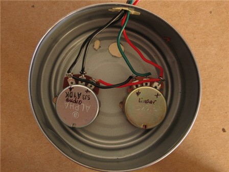
Figure 5. Wiring the potentiometers. You can daisy-chain the +5 V wire (red) between the pots (right hand lug, when viewed from beneath, as in the photo). You can also daisy-chain the ground wire (black; left-hand lug, when viewed from beneath, as in the photo). The center lug is what goes to the non-inverting input of the op-amp (pin 3). To keep your connections straight, use a wire color that resembles the color of the knob (or label the wires). - Add the labels (print-out and instructions available) and knobs (Figure 6), and this part is done.
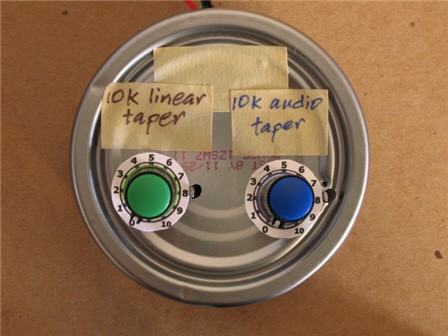
Figure 6. Completed potentiometer controls mounted in a tunafish can.
/-/https/www.sciencebuddies.org/cdn/Files/2893/3/Elec_img096.jpg)
/-/https/www.sciencebuddies.org/cdn/Files/2894/3/Elec_img097.jpg)
Soldering Leads to the LED and Light-to-Voltage Converter
- Both the LED and the light-to-voltage converter can be damaged by too much heat. In order to protect these components from heat, use the needle-nose pliers as a heat sink while soldering.
- Put a rubber band around the handle of the pliers to hold the jaws closed.
- Spread the jaws open and slide the leads of the component to be soldered into the pliers.
- The pliers should be right next to the base of the component, with the free ends of the leads sticking out, leaving you plenty of room to solder (see Figure 7).
- Solder a wire of the appropriate length onto each component lead. For the LED, use a red wire for the + lead (anode, longer), and a black wire for the − lead (cathode, shorter). For the light-to-voltage converter, use a red wire for the +5 V lead, and a black wire for the ground lead. If you have another color of wire, use it for the output lead. If not, clearly label your leads so you know which is which.
- Check to make sure you have a good connection, then slide a piece of shrink tubing over the lead, and shrink it into place with a blast of hot air from a blow dryer. Figure 7 shows the completed LED with soldered wire leads.
/-/https/www.sciencebuddies.org/cdn/Files/2897/3/Elec_img100.jpg)
Figure 7. Completed LED with wires soldered to leads. The yellow bar marks where the needle-nose pliers should be clamped to protect the LED during soldering. Use heat shrink tubing after soldering is completed to fully insulate the component leads.
Building the LED Control Circuit
- Next, you'll build the LED control circuit on the solderless breadboard. You can learn how to use a breadboard in the Science Buddies reference How to Use a Breadboard for Electronics and Circuits. Tips for working with the breadboard:
- Remember that the power supply for the breadboard should always be off when you are building the circuit!
- Use the jumpers to make your connections neatly (i.e., use straight lines, right angles whenever possible). A neater circuit has several advantages:
- You have easier access to circuit points when you want to make voltage measurements with your digital multimeter.
- The circuit is easier to understand.
- You are less likely to make wiring mistakes, and more likely to catch them if you do.
- Figure 10 shows a detail photo of the completed circuit on the breadboard for your reference.
- The LF411CN chip used in this project is an example of an integrated circuit (IC). The electronics industry has several different ways of making ICs, so you can often buy the same IC in several different physical formats or "packages." The LF411CN part used in this project is called a "dual inline plastic" (or "DIP") package.
- A DIP IC has two rows of metal "pins" coming out from each side. Figure 8 shows pin numbering scheme for the LF411 DIP package. The semi-circular depression at one end of the chip marks the "top" end of the chip. In this orientation, pin 1 is at the top left. (This is the electronics industry standard for all DIP packages.) Pin 1 is often additionally marked with a small circular depression. You count pin numbers down the pin 1 side, and then back up the other side. Thus on an 8-pin DIP, pin 8 is opposite pin 1, pin 7 is opposite pin 2, pin 6 is opposite pin 3, and pin 5 is opposite pin 4.
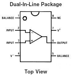
Figure 8. Pin numbering scheme for the LF411 DIP IC. The small semi-circular depression marks the top end of the chip. Pin 1 is at the top left. Often, the chip will also have a small circular depression next to the pin to mark pin 1. You count pin numbers down the pin 1 side, and then back up the other side. - Figure 9 shows the schematic for an individual LED control. The numbers 2, 3, and 6 show which pin on LF411 IC chip corresponds to the connection in the schematic. Each LED gets its own control, so you need to make three copies of this circuit on your breadboard. Notice that the schematic does not show the connections for power to the LF411 (V+, pin 4, and V−, pin 7).
Figure 9. Schematic of a single LED control circuit (Calvert, 2002). - Insert the LF411 IC into the breadboard so that chip straddles one of the gaps in the rows of holes. Make sure that each of the 8 pins is aligned with its proper hole, then carefully push the chip straight down.
- The first connections to make are the power supply connections for the LF411. Use jumper wires to connect the +15 V bus to pin 7 and the −15 V bus to pin 4.
- Next connect the 330 Ω resistor. One end of the resistor connects to pin 2, the other end connects to the ground bus. Use a needle-nose pliers to make 90° bends in the leads at the proper stance, then trim each lead to about 7-8 mm below the bend. Insert the resistor into the breadboard.
- Next connect the LED. Remember that the anode (+ lead) connects to pin 6, and the cathode (− lead) connects to pin 2.
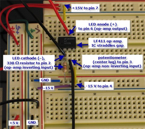
A photo of a circuit on a breadboard for a variable current LED has labels for specific inputs. From top to bottom the labels read: +15V to pin 7, LED anode (+) to pin 6 (op-amp output), LF411 op-amp IC straddless gap, potentiometer (center lug) to pin 3 (op-amp non-inverting input), -15V to pin 4, and LED cathode (-) 330 ohm resistor to pin 2 (op-amp inverting input).
Figure 10. Detail view of completed circuit on breadboard. Notice how the LF411 ICs span the gap between the holes in the breadboard. Power connections to the chip are made to pin 7 (+15 V) and pin 4 (−15 V). The 330 Ω resistor is connected between pin 2 and the ground bus. The anode (+ lead, red) of the LED connects to pin 6, and the cathode (− lead, black) connects to pin 2. The wire from the center lug of the potentiometer connects to pin 3. Don't forget to connect the +5 V and ground leads of the potentiometer to the corresponding bus lines on the breadboard.
/-/https/www.sciencebuddies.org/cdn/Files/2892/3/Elec_img092.jpg)
/-/https/www.sciencebuddies.org/cdn/Files/2895/3/Elec_img098.jpg)
Building the Light Detection Circuit
- The circuit is very simple. The light-to-voltage converter is an integrate d package that contains a photodiode and an amplifier. The functional block diagram is shown in Figure 11.
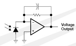
Figure 11. Light-to-voltage converter functional block diagram (TAOS, Inc., 2006).
Light (indicated by arrows) illuminates the photodiode sensor and generates a current. The op-amp produces an output voltage that is proportional to the intensity of the light illuminating the photodiode. - A drawing of the actual component is shown in Figure 12. The round window contains the light-sensitve region. The component has three pins, as shown.
- Pin 1 should be connected to ground.
- Pin 2 should be connected to +5 V .
- Pin 3 is the output voltage, a signal that is proportional to the amount of light falling on the sensor. It should connect to a 10 kΩ resistor, which, in turn, is connected to ground (see Figure 13).
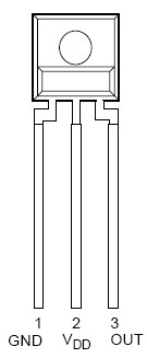
Figure 12. Drawing of light-to-voltage converter package (TAOS, Inc., 2006).
- Figure 13 is a schematic diagram of the complete light detection circuit. In addition to the light-to-voltage converter, there is only one more component: a 10 kΩ resistor (RL). Connect the resistor from pin 3 to ground, as shown.
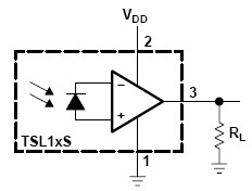
Figure 13. Light-to-voltage converter circuit schematic (TAOS, Inc., 2006). - The output signal of the light detection circuit is the voltage drop across the 10 kΩ resistor. To read the output, use one alligator clip lead to connect the positive lead of the resistor to the red probe of your digital multimeter (DMM), and another clip lead to connect the grounded lead of the resistor to the black probe of your DMM. Set your DMM to read DC Volts. If you need help using a multimeter, check out the Science Buddies reference How to Use a Multimeter.
/-/https/www.sciencebuddies.org/cdn/Files/2889/5/ApMech_img014.jpg)
/-/https/www.sciencebuddies.org/cdn/Files/2890/5/ApMech_img015.jpg)
/-/https/www.sciencebuddies.org/cdn/Files/2891/5/ApMech_img016.jpg)
/-/https/i.ytimg.com/vi/ts0EVc9vXcs/maxresdefault.jpg)
Making Light Measurements
- With the power to the breadboard off, connect the two voltmeters.
- Use alligator clips to connect the first voltmeter across the 330 Ω resistor. The voltage across this resistor is proportional to the current through the LED (you can use Ohm's Law to calculate the LED current).
- Use alligator clips to connect the second voltmeter across the 10 kΩ resistor (output of the light-to-voltage converter).
- Position the LED and light-to-voltage converter. Here are some tips for getting your setup "just right":
- Each component should be securely fastened to a support (such as a block of wood), and placed on a sturdy support.
- Double-check all of your connections, then turn on the power to the breadboard.
- Let there be light! Turn up the potentiometer, and you should see the LED light up. (If not, power down and re-check your connections.)
- With the LED is aimed at the detector and close enough to it, you should also see a non-zero voltage reading on the DMM.
- The LED has a narrow viewing angle (15°), so it is important to have the LED and the light detector at the same height, and aligned with each other. You can tell when the alignment is optimal by watching the output from the light detector on your DMM.
- You also need to set the distance between the LED and the detector so that the output signal is just under <5 V (max. output signal) with the potentiometer all the way up. That way you'll be using the full dynamic range of the detector.
- If the tension from the lead wires prevents the components from staying put, tape the lead wires down to the table. This "strain relief" will make your life easier.
- Figure 14 is an illustration of one possible setup for making the light measurements.
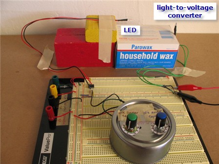
Figure 14. One possible setup for making the light measurements. This photo shows both the circuit assembly and the LED and light-to-voltage converter. A better way to do it would be to use the long lead wires so that the circuit and potentiometers are supported separately. That way you won't disturb the alignment of the LED and light detector when you make adjustments to the potentiometers.
- Measure the LED current and light output.
- You'll get the best results if you make your measurements in a darkened or dimly lit room. You want the baseline reading from the light detector to be as low as possible. Use a flashlight to illuminate the voltmeters to get your readings, but make sure the light from the flashlight doesn't fall on the light detector.
- Use the linear potentiometer first. Get at least three sets of measurements, then power down the breadboard and connect the audio potentiometer.
- At each setting on the potentiometer dial, observe the LED and note the change in apparent brightness—what it looks like to your eye, compared to the previous setting. Then record the voltage across the 330 Omega; resistor (you'll calculate LED current from this) and the voltage across the 10 kΩ resistor (the light detector output).
- Keep track of your results with a table in your lab notebook. (The first four columns are your measurements and observations, the remaining columns are calculated.)
pot. type:___________________ pot.
settingSubjective brightness
(compared to previous setting)Vr
(V)Vp
(V)ILED
(mA)Vp − V0
(V)ΔV
(V)0 1 2 etc.
/-/https/www.sciencebuddies.org/cdn/Files/2896/3/Elec_img099.jpg)
Analyzing Your Results
- Use Ohm's Law to calculate the LED current from Vr, the voltage across the 330 Ω resistor (column 4 in the data table). Tip: measure the actual resistor value with your DMM before making this calculation.
- The light detector voltage, V0 when the LED is off (potentiometer at 0 setting) is the baseline "dark" level. Subtract this reading from all of the other readings (column 5 in the data table).
- The final column, ΔV, is a measure of the light detector voltage change with each 30° increment of the potentiometer knob. Subtract the previous reading from the current reading. For example, to calculate ΔV for potentiometer setting "5", subtract the reading from setting "4" from the reading for setting "5".
- Make graphs of your results. Here are some suggestions:
- Graph LED current as a function of potentiometer setting.
- Graph corrected detector voltage (Vp − V0) as a function of LED current.
- Graph ΔV as a function of LED current.
- Which potentiometer seems to your eye to produce a constant increment in light intensity with each setting?
- Compare your subjective impression with what the measurement from the light detector. What does this tell you about your perception of light intensity?
Ask an Expert
Global Goals
The United Nations Sustainable Development Goals (UNSDGs) are a blueprint to achieve a better and more sustainable future for all.
/-/https/www.sciencebuddies.org/cdn/Files/19752/5/E-WEB-Goal-09.png)
Variations
- Try adding a 2.2 kohm resistor between the center lug of the audio taper potentiometer and ground (Elliott, 2001). What does the shape of the light output curve look like now?
- Investigate simple audio amplifier circuits and compare using an audio taper potentiometer vs. a linear taper potentiometer for a volume control.
Careers
If you like this project, you might enjoy exploring these related careers:
/-/https/careerdiscovery.sciencebuddies.org/cdn/Files/1147/17/unsplash-fJebhGIP0P4.jpg)
/-/https/careerdiscovery.sciencebuddies.org/cdn/Files/1223/17/iStock-971549326.jpg)
/-/https/careerdiscovery.sciencebuddies.org/cdn/Files/1233/17/unsplash-b28ac533a45f.jpg)
/-/https/careerdiscovery.sciencebuddies.org/cdn/Files/1242/20/iStock-113511101.jpg)

/-/https/img.youtube.com/vi/zACmjwvbils/0.jpg)
/-/https/img.youtube.com/vi/DV5d31z1xTI/0.jpg)
/-/https/img.youtube.com/vi/mJCtvZskziI/0.jpg)