Abstract
A mass driver uses electromagnetics to launch projectiles. In the future, such a device could launch payloads into space without the use of chemical rockets. This could lead to long-term cost savings when launching large amounts of material into space—for example, to construct a space station. In this project you will design and build your own working model mass driver as you learn some of the engineering principles behind how mass drivers operate.
Summary
Previous experience with electronics and Arduino is recommended.
A kit is available from our partner Home Science Tools®. See the Materials section for details.
Wire coils can get hot to the touch.
/-/https/i.ytimg.com/vi/GFJSwrSvlN4/maxresdefault.jpg)
Objective
Design and build a working model mass driver.
Introduction
A mass driver—also called an electromagnetic catapult, space gun, or coil gun—is a type of linear motor. That means it produces linear motion instead of rotational motion. Mass drivers use a series of electromagnets to accelerate an object to high speeds. One day, they could be used to launch payloads into space from the surface of the Earth or the Moon (Figure 1).
/-/https/www.sciencebuddies.org/cdn/Files/18960/15/lunar-mass-driver.jpg)
Figure 1. Artist's conception of a mass driver on the surface of the Moon (Source: NASA).
A basic mass driver consists of a hollow tube with a ferromagnetic payload, like a cylindrical piece of steel. Wires coiled around the outside of the tube form electromagnets that generate a magnetic field when electrical current passes through them. This external magnetic field induces a magnetic field in the ferromagnetic payload, causing it to be pulled toward the coil.
Once the payload passes through the coil, though, it is pulled back toward the center of the coil and eventually settles there. To avoid this, the coil must be switched off as soon as the payload passes through it. This allows the payload to continue traveling forward.
A mass driver can use multiple stages to accelerate the payload to increasingly higher speeds. At each stage, the coil turns on as the payload approaches, then turns off as soon as the payload passes through (Figure 2).
/-/https/www.sciencebuddies.org/cdn/Files/18961/13/3-stage-mass-driver.png)
In stage 1, coil 1 is energized and the payload is attracted toward it. In stage 2, the first coil is turned off and the second coil is turned on, so the payload keeps moving forward and is attracted to coil 2. In stage 3, the second coil is turned off and the third coil is turned on. Once the payload reaches coil 3, all coils are turned off and the payload exits the tube.
Figure 2. Diagram showing the operation of a three-stage mass driver.
This raises the interesting question of timing. How do you know when to turn each coil on and off? In theory, you could use physics to predict how fast the payload will move, calculate how long it will take to reach each position in the tube, and manually set the timing for each coil (e.g., "Turn on coil 1 for 0.1 seconds, then turn off coil 1 and turn on coil 2 for 0.1 seconds..."). This approach is called open-loop control. It is difficult, however, and does not account for potential variability in the system from one launch to the next.
Instead, you can use sensors to detect the position of the payload in the tube, and then use closed-loop control (also called feedback control) to automatically turn the coils on and off based on the payload's position. Instead of manually setting the times, you can write a program with an algorithm like this: "Turn on coil 1. Once the sensor detects that the payload has exited coil 1, turn on coil 2." In particular, you can use a Hall effect sensor, which detects magnetic fields and therefore can detect when the ferromagnetic payload passes by in the tube.
In this project, you will design and build a model mass driver controlled by an Arduino®. The project procedure will give you basic instructions for building a three-stage mass driver; however, there are many variables you can tweak to optimize the design of your mass driver. Can you design a mass driver that launches a payload as far or as fast as possible?
Terms and Concepts
- Mass driver
- Electromagnetic catapult
- Space gun
- Coil gun
- Linear motor
- Ferromagnetic
- Stage
- Open-loop control
- Sensor
- Closed-loop control
- Feedback control
- Hall effect sensor
Questions
- What are some potential uses of mass drivers?
- What are the potential advantages of a mass driver over chemical rockets?
- What are some of the technical hurdles that must be overcome for the construction of large-scale mass drivers?
Bibliography
- Wikipedia users (n.d.). Mass driver. Retrieved August 26, 2022.
- Science Buddies Staff (n.d.). Electricity, Magnetism, & Electromagnetism Tutorial. Retrieved August 26, 2022.
- Science Buddies Staff (n.d.). How to Use an Arduino. Retrieved August 26, 2022.
- Science Buddies Staff (n.d.). Engineering Design Process. Retrieved August 26, 2022.
Materials and Equipment 
Recommended Project Supplies
/-/https/www.sciencebuddies.org/cdn/Files/19915/12/SB_ARDNSTR_web__01473.jpg)
-
Electronics Kit for Arduino, available from our partner Home Science Tools®.
- Note: This project will work with the Arduino UNO R3, UNO R4 Minima, UNO R4 WiFi, and compatible third-party boards.
- Windows or Mac computer. See this page if you have a Chromebook. Your computer will need:
- Access to the Arduino IDE, either installed local version or web-based editor (note that Chromebooks can only use the web version). Watch this video for a comparison of the two options.
- USB port. The Science Buddies kit comes with a USB-A to B cable. The "B" end plugs into the Arduino and the "A" end plugs into your computer. You will need an adapter or different cable if your computer only has USB-C ports. Watch this video to learn about the different types of cables and adapters.
- You will also need to gather the following items, not included in the kit:
- 22 AWG hookup wire (recommended colors: red, black, and one other)
- A3144 digital Hall effect sensors (3)
- Alligator clip leads
- 6 V lantern batteries (3)
- 4-channel MOSFET driver module
- 22 AWG enameled magnet wire
- 8 mm ID 10 mm OD rigid clear acrylic tube
- 1/4" diameter steel rod, available at a hardware store (do not buy stainless steel, as it may not be magnetic)•
- Wire strippers
- Soldering iron and soldering supplies
- Fine- or medium-grit sandpaper
- Electrical tape
- Optional: heat shrink tubing
- Hacksaw
- Ruler
- Small Phillips head screwdriver
- Small cardboard box
- Pencil
- Thin permanent marker
- Tape measure
- Lab notebook
Experimental Procedure
This procedure will show you how to build a mass driver using the items in the materials list. Remember that you can try different materials or change the dimensions of the mass driver for your project. See the end of the procedure for some suggestions about things you can change.
/-/https/i.ytimg.com/vi/GFJSwrSvlN4/maxresdefault.jpg)
- Use a hacksaw to cut a piece of the steel rod a few centimeters long to make your projectile.
- Wrap magnet wire around the acrylic tube to form your coils. Figure 3 shows a 3-stage tube with three coils, each consisting of 450 turns of 22 AWG magnet wire.
- The coils should not be longer than your projectile—that way, you can immediately detect when the projectile has passed the center of the coil.
- Make sure you wrap each coil in the same direction.
- Leave at least 30 cm of wire at each end of each coil so you can connect them to the drive board.
- Use sandpaper to strip insulation from about the last centimeter of each wire.
- Hold the coils in place with electrical tape so they do not unravel.
- To make winding the coils easier, you can make a simple wire spool holder with a cardboard box and a pencil (Figure 4). You can also use a power drill to help wind the coils.
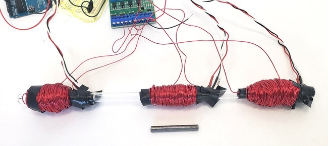
Figure 3. Mass driver tube with three electromagnetic coils.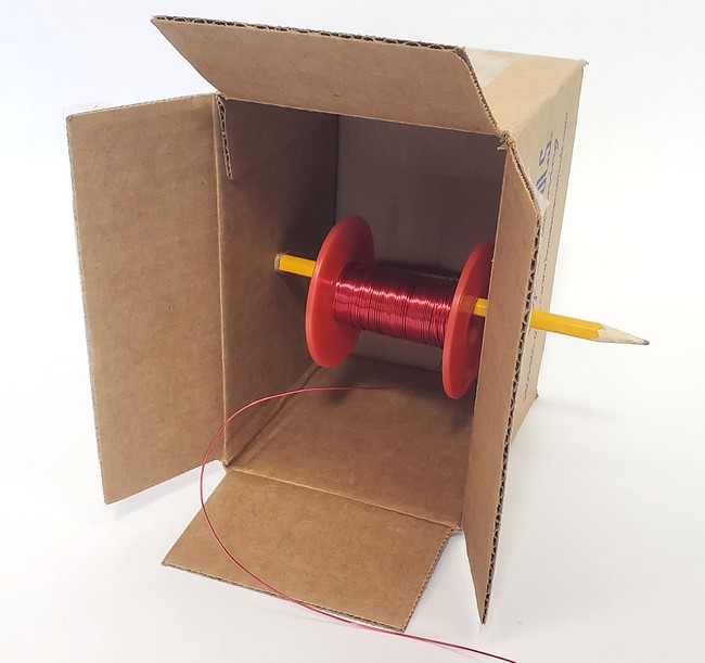
Figure 4. Simple wire spool holder made from a cardboard box and a pencil. - Solder extension wires to three of your Hall effect sensors (Figure 5).
- Make the wires at least 30 cm long so you can mount the sensors on the tube and connect the wires to your Arduino.
- With the writing on the sensor facing you, from left to right the pins are power, ground, and output. It helps to color-code your wires. For example, use red for power, black for ground, and a different color for output.
- Wrap the connections to the pins in electrical tape or heat shrink tubing to prevent short circuits.
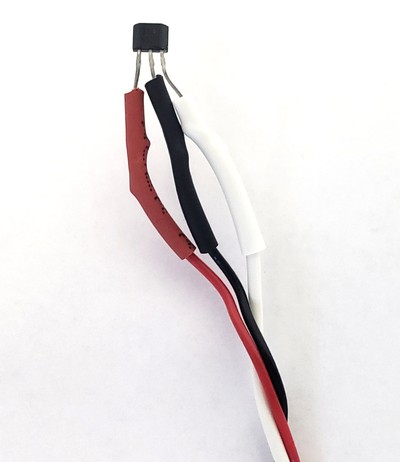
Figure 5. Extension wires soldered to Hall effect sensor and covered in heat shrink tubing. - Tape a Hall effect sensor to the tube, with the flat side (the side without any writing) against the tube, immediately after each coil. In Figure 3 you can see where the Hall effect sensor wires are connected to the tube (the sensors themselves are concealed by tape).
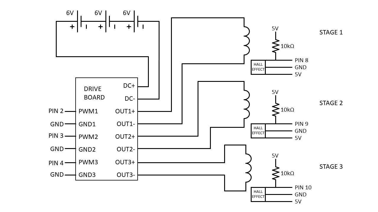
- Build the circuit as shown in Figure 6. Your completed setup should look like the one in Figure 7.
- Connect the first coil to OUT1+ and OUT1- on the drive board.
- Connect the second coil to OUT2+ and OUT2- on the drive board.
- Connect the third coil to OUT3+ and OUT3- on the drive board.
- Use alligator clips to connect your three batteries in series (positive to negative).
- Connect the battery bank's negative terminal to DC- on the drive board.
- Prepare to connect the battery bank's positive terminal to DC+ on the drive board, but leave the alligator clip disconnected for now so the circuit is not powered on.
- Connect Arduino pin 2 to PWM1 on the drive board.
- Connect Arduino pin 3 to PWM2 on the drive board.
- Connect Arduino pin 4 to PWM3 on the drive board.
- Connect GND1, GND2, and GND3 on the drive board to GND on the Arduino.
- Connect the first stage Hall effect sensor:
- Pin 1 (red wire) to 5V
- Pin 2 (black wire) to GND
- Pin 3 (other color) to Arduino pin 8
- Add a 10 kΩ pull-up resistor from sensor pin 3 to 5V.
- Connect the second stage Hall effect sensor:
- Pin 1 (red wire) to 5V
- Pin 2 (black wire) to GND
- Pin 3 (other color) to Arduino pin 9
- Add a 10 kΩ pull-up resistor from sensor pin 3 to 5V.
- Connect the third stage Hall effect sensor:
- Pin 1 (red wire) to 5V
- Pin 2 (black wire) to GND
- Pin 3 (other color) to Arduino pin 10
- Add a 10 kΩ pull-up resistor from sensor pin 3 to 5V.
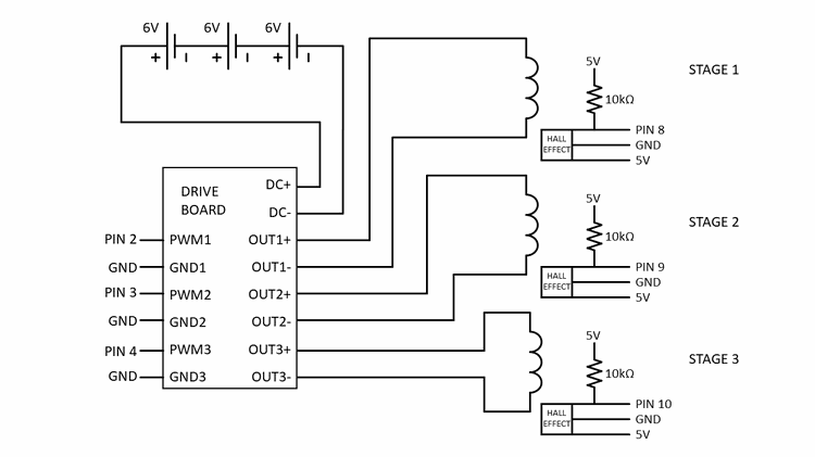
Figure 6. Circuit diagram for the Arduino mass driver with MOSFET drive board. Click here for a larger version of the image.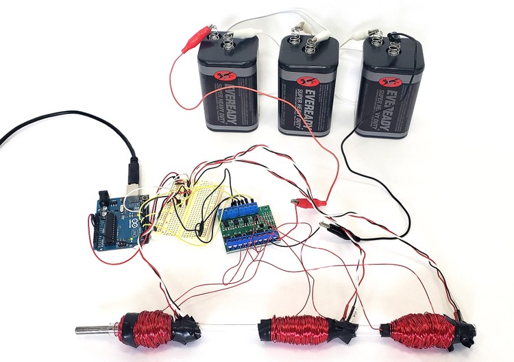
Figure 7. Mass driver experimental setup. - Download mass_driver_3_stage.ino and read through the commented code. Make sure you understand how it works. The code starts by turning on the first coil, then uses the Hall effect sensors to know when to turn each coil on and off.
- Upload the code to your Arduino.
- Make sure your mass driver tube is not pointed at any people, animals, or anything it might damage. A pillow or cardboard box is a good target.
- Place your projectile partially into the entrance of the tube (near coil 1), as shown in Figure 8.
- Connect the final alligator clip to your battery bank, providing power to your circuit.
- Press the reset button on your Arduino. Your projectile should be sucked in, then launched through the tube!
- If your mass driver did not work, you might need to do some troubleshooting. A multimeter can be a very useful tool for debugging circuits, if you have one available.
- This is a complicated circuit. Double-check all of your wiring. Sometimes it can be hard to spot your own mistakes, so it can help to have another person double-check your wiring as well.
- If your projectile did not get sucked into the tube at all, make sure it is not simply stuck in the entrance. Try placing it slightly farther inside the tube, then press the reset button on your Arduino again.
- You can confirm that your coils are working by disconnecting them from the drive board and connecting them, one at a time, directly to the battery bank. If you place the steel projectile near a coil and then connect the coil to the battery, the projectile should be sucked in to the middle of the coil. If you only briefly touch the battery contact with an alligator clip then remove it, the coil will de-energize and the projectile should continue to travel through the tube.
- You can test your Hall effect sensors using a permanent magnet and a multimeter. Measure the sensor's output pin with a multimeter and bring a permanent magnet near the sensor. Its output should change from 5 V to 0 V. If you do not have a multimeter available, you can also debug the sensors using the Serial.print command in your Arduino program. For example, make the program print out "high" or "low" depending on whether the sensor reading is high or low.
- The drive board has onboard LEDs that turn on when each respective input is active. Watch the board closely and you should see the LEDs light up in sequence as the projectile travels through the tube. If all three LEDs do not light up in order, you might have a problem with one of your sensors.
- You should now have your basic mass driver working. It is up to you to improve the design or test a variable for a science or engineering project. You will need to decide how you will measure your mass driver's performance. (For example, use a tape measure to measure how far the projectile travels). Here are a few things you can try. For more advanced ideas, see the Variations section. What happens if you:
- Add more batteries to the battery bank in series? In parallel?
- Add more stages?
- Change the spacing between stages?
- Change the number of turns in each coil?
- Change the wire gauge of the coils?
- Change the size of the payload?
- Launch the payload at an angle?
- Change the launch tube and/or projectile diameter?
- Use a cylindrical magnet instead of a steel rod as the projectile?
/-/https/www.sciencebuddies.org/cdn/Files/18962/13/mass-driver-tube-coils.jpg)
/-/https/www.sciencebuddies.org/cdn/Files/18963/13/wire-spool-holder-mass-driver.jpg)
/-/https/www.sciencebuddies.org/cdn/Files/18964/13/hall-effect-sensor-wires.jpg)
/-/https/www.sciencebuddies.org/cdn/Files/18965/13/mass-driver-circuit-diagram.png)
/-/https/www.sciencebuddies.org/cdn/Files/18959/13/arduino-mass-driver.jpg)
Ask an Expert
Global Goals
The United Nations Sustainable Development Goals (UNSDGs) are a blueprint to achieve a better and more sustainable future for all.
/-/https/www.sciencebuddies.org/cdn/Files/19752/5/E-WEB-Goal-09.png)
Variations
- Try experimenting with different power supplies for your mass driver. For example, what happens if you use a DC wall adapter or a bank of supercapacitors instead of batteries?
- Can you film your mass driver in slow motion and measure your projectile's speed as it travels through each stage? Can you calculate the net force acting on the projectile using Newton's laws of motion?
- Alternatively, can you calculate your projectile's speed based on the distances between the Hall effect sensors and the elapsed time between their activation?
- Can you design your own drive electronics for the circuit instead of buying a preassembled drive board? This is an advanced electrical engineering project. Here are a few videos where people take different approaches:
- Is a mass driver the cheapest way to launch material into space? What about reusable rockets? You can explore these topics in your own science project: What is the Cheapest Way to Launch Payloads into Space?
Careers
If you like this project, you might enjoy exploring these related careers:
/-/https/careerdiscovery.sciencebuddies.org/cdn/Files/1223/17/iStock-971549326.jpg)
/-/https/careerdiscovery.sciencebuddies.org/cdn/Files/835/18/msfc-202000343.jpg)
/-/https/careerdiscovery.sciencebuddies.org/cdn/Files/1450/21/iStock-1227179796.jpg)
/-/https/careerdiscovery.sciencebuddies.org/cdn/Files/1640/26/Fyysikot_tyossaan.jpg)
/-/https/careerdiscovery.sciencebuddies.org/cdn/Files/19494/4/female-engineer-using-robot-hand-welding.jpg)
Contact Us
Our kits are developed in partnership with Home Science Tools®. If you have purchased a kit for this project, Home Science Tools® is pleased to answer any questions.In your email, please follow these instructions:
- Include your Home Science Tools® order number.
- Please describe how you need help as thoroughly as possible:
Examples
Good Question I'm trying to do Experimental Procedure step #5, "Scrape the insulation from the wire. . ." How do I know when I've scraped enough?
Good Question I'm at Experimental Procedure step #7, "Move the magnet back and forth . . ." and the LED is not lighting up.
Bad Question I don't understand the instructions. Help!
Good Question I am purchasing my materials. Can I substitute a 1N34 diode for the 1N25 diode called for in the material list?
Bad Question Can I use a different part?
Contact Support

/-/https/img.youtube.com/vi/zACmjwvbils/0.jpg)
/-/https/img.youtube.com/vi/DV5d31z1xTI/0.jpg)
/-/https/img.youtube.com/vi/mJCtvZskziI/0.jpg)