Abstract
The Pomodoro technique is a popular study method consisting of alternating study sessions and breaks. In this engineering project you will build your own customized Pomodoro timer or clock using an Arduino. In addition to displaying the time, you can use your clock to display messages or get the user's attention using lights, sound, or even moving parts. Can you work more efficiently with a Pomodoro timer at your side? Build one and find out!
Summary
None
A kit is available from our partner Home Science Tools®. See the Materials section for details.
No issues
/-/https/i.ytimg.com/vi/xf4Bnm8edAg/maxresdefault.jpg)
Objective
Design and build a customized Pomodoro timer.
Introduction
The Pomodoro technique is a time management method consisting of 25-minute work or study sessions followed by 5-minute breaks. After four study sessions, you take a longer break, typically 15 or 20 minutes, then you repeat the entire process. The name comes from the tomato-shaped kitchen timer (Figure 1) used by the person who invented the technique (pomodoro means tomato in Italian).
/-/https/www.sciencebuddies.org/cdn/Files/19902/10/pomodoro-timer.jpg)
Figure 1. A tomato-shaped kitchen timer. (Image credit Wikimedia Commons user Erato, CC By-SA 2.5)
You can make your own customized Pomodoro timer using an Arduino with an LCD screen (Figure 2). You can display the current session time along with other information or messages on the screen, like the number of study cycles completed so far, or an inspirational message. You can also add other outputs to your circuit like LEDs, buzzers, or even motors. You can use these outputs to get the user's attention at transition times or to indicate whether they are currently in a study period or a break.
/-/https/www.sciencebuddies.org/cdn/Files/19901/11/arduino-pomodoro-timer.jpg)
Figure 2. An electronic Pomodoro timer made using an LCD screen controlled by an Arduino.
To do this project, you will need to know how to use an LCD screen with an Arduino. That information is covered in the following tutorial video. It is up to you what else you will decide to add to your project. Many other Arduino tutorials are available from the reference in the Bibliography.
/-/https/i.ytimg.com/vi/s_-nIgo71_w/maxresdefault.jpg)
Terms and Concepts
- Pomodoro technique
Questions
- What are some benefits of using the Pomodoro technique to study?
- How could you customize a Pomodoro timer? What else could you add to it?
Bibliography
- Sheldon, R. (n.d.). Pomodoro Technique. TechTarget. Retrieved September 27, 2023.
- Finio, B. (n.d.). How to Use an Arduino. Science Buddies. Retrieved September 27, 2023.
Materials and Equipment 
Recommended Project Supplies
/-/https/www.sciencebuddies.org/cdn/Files/19915/12/SB_ARDNSTR_web__01473.jpg)
Since this is an engineering design project, you will need to decide what other parts to add to your timer. The following list shows exactly what you need to build the timer shown in the procedure.
-
Electronics Kit for Arduino, available from our partner Home Science Tools®.
- Note: This project will work with the Arduino UNO R3, UNO R4 Minima, UNO R4 WiFi, and compatible third-party boards.
- 1602 LCD screen (the example code in this project uses parallel communication, not I2C)
- LEDs (2), colors of your choice (the Science Buddies kit only comes with red)
- Lab notebook
- Windows or Mac computer. See this page if you have a Chromebook. Your computer will need:
- Access to the Arduino IDE, either installed local version or web-based editor (note that Chromebooks can only use the web version). Watch this video for a comparison of the two options.
- USB port. The Science Buddies kit comes with a USB-A to B cable. The "B" end plugs into the Arduino and the "A" end plugs into your computer. You will need an adapter or different cable if your computer only has USB-C ports. Watch this video to learn about the different types of cables and adapters.
Disclaimer: Science Buddies participates in affiliate programs with Home Science Tools®, Amazon.com, Carolina Biological, and Jameco Electronics. Proceeds from the affiliate programs help support Science Buddies, a 501(c)(3) public charity, and keep our resources free for everyone. Our top priority is student learning. If you have any comments (positive or negative) related to purchases you've made for science projects from recommendations on our site, please let us know. Write to us at [email protected].
Experimental Procedure
- Decide what additional parts (buzzers, motors, etc.), if any, you will include in your timer.
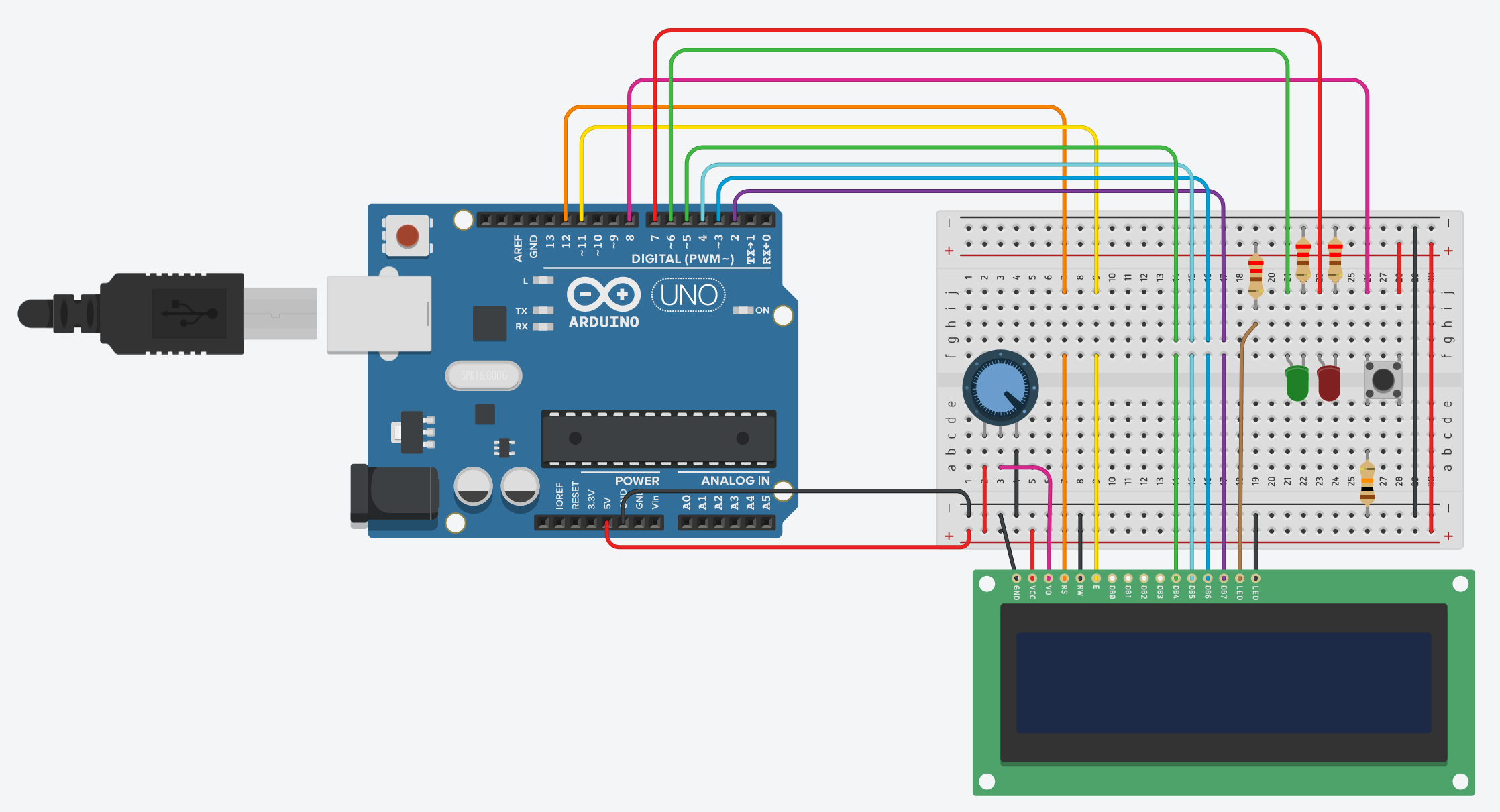
- Assemble your circuit on the breadboard as shown in Figure 3. You can also access a Tinkercad Circuits version of the circuit or follow this list of connections:
- LCD screen pins (from left to right—depending on which screen you bought, your labels may be slightly different):
- GND to GND
- VCC to 5V
- V0 to potentiometer center pin
- RS to Arduino pin 12
- E to Arduino pin 11
- DB0 through DB3 — leave unconnected
- DB4 to Arduino pin 5
- DB5 to Arduino pin 4
- DB6 to Arduino pin 3
- DB7 to Arduino pin 2
- LED+ to 5V through a 220 Ω resistor
- LED- to GND
- Potentiometer (if you are not sure how to wire a potentiometer, see the Use a Potentiometer section of our Arduino tutorial)
- One outer pin to 5V
- One outer pin to GND
- Middle pin to LCD screen pin V0 (this connection should already be made if you followed the steps above)
- Green LED (if you are not sure how to wire an LED, see the Blink an External LED section of our Arduino tutorial)
- Positive lead (anode) to Arduino pin 6
- Negative lead (cathode) to GND through a 220 Ω resistor
- Red LED
- Positive lead (anode) to Arduino pin 7
- Negative lead (cathode) to GND through a 220 Ω resistor
- Pushbutton (if you are not sure how to wire a button, see the Use a Button section of our Arduino tutorial)
- One side to Arduino pin 8 with a 10 kΩ pulldown resistor to GND
- Other side to 5V
- LCD screen pins (from left to right—depending on which screen you bought, your labels may be slightly different):
/-/https/www.sciencebuddies.org/cdn/Files/19904/9/arduino-pomodoro-timer-circuit.png)
Figure 3. Breadboard diagram for the Pomodoro timer circuit. (Click to access a larger version of the diagram.)
- Using the remaining Arduino pins, connect any additional hardware like buzzers or motors to your circuit.
- Download the Pomodoro timer example code, or copy the code from the Tinkercad Circuits link. Read through the commented code so you understand how it works.
- Edit the code to control any additional hardware that you added to your circuit. For example, you can make a buzzer go off or a motor spin to get the user's attention at transition times between study and break periods.
- Test your timer to make sure everything works. You may want to shorten the duration of the study and break periods in the code so you do not have to sit there for 25 minutes to observe the first transition. After you have tested and confirmed that everything works, you can return the variables to their default values.
- Try using your timer! You can use it yourself the next time you need to do homework or study, or let someone borrow it. You can even let an adult use it at work. Get feedback about your Pomodoro timer. What improvements or changes can you make to the design? See the Variations section for some suggestions.
Ask an Expert
Global Goals
The United Nations Sustainable Development Goals (UNSDGs) are a blueprint to achieve a better and more sustainable future for all.
/-/https/www.sciencebuddies.org/cdn/Files/19747/5/E-WEB-Goal-04.png)
Variations
- Can you change the code so the timer for each session counts down instead of up?
- Can you display the current session number on the screen? For example "Study session 1/4."
- Can you make a case for your timer so all the electronics and wires are hidden (except for the outputs and controls, like the screen, LEDs, and buttons)? You can use any materials you have access to, ranging from a simple cardboard box to wood or a 3D printer. Can you make it look like a desktop clock that you could buy at a store?
- Can you make a "soft" timer by mounting all the electronics inside a stuffed animal?
- Can you add controls so the user can customize the duration of the study and break sessions without needing to edit and re-upload the code?
- Can you add voice control to your timer?
- Can you do an experiment to see if people using a Pomodoro timer can study or work more effectively than people without one?
Careers
If you like this project, you might enjoy exploring these related careers:
/-/https/careerdiscovery.sciencebuddies.org/cdn/Files/1223/17/iStock-971549326.jpg)
/-/https/careerdiscovery.sciencebuddies.org/cdn/Files/1147/17/unsplash-fJebhGIP0P4.jpg)
/-/https/careerdiscovery.sciencebuddies.org/cdn/Files/1011/20/pexels-photo-7375.jpg)
/-/https/careerdiscovery.sciencebuddies.org/cdn/Files/1163/18/pexels-photo-1181472.jpg)
Contact Us
Our kits are developed in partnership with Home Science Tools®. If you have purchased a kit for this project, Home Science Tools® is pleased to answer any questions.In your email, please follow these instructions:
- Include your Home Science Tools® order number.
- Please describe how you need help as thoroughly as possible:
Examples
Good Question I'm trying to do Experimental Procedure step #5, "Scrape the insulation from the wire. . ." How do I know when I've scraped enough?
Good Question I'm at Experimental Procedure step #7, "Move the magnet back and forth . . ." and the LED is not lighting up.
Bad Question I don't understand the instructions. Help!
Good Question I am purchasing my materials. Can I substitute a 1N34 diode for the 1N25 diode called for in the material list?
Bad Question Can I use a different part?
Contact Support

/-/https/img.youtube.com/vi/NV6YHZ2RAqc/0.jpg)
/-/https/img.youtube.com/vi/gcpyjQLqL9I/0.jpg)
/-/https/img.youtube.com/vi/ZAsGHhWxwpM/0.jpg)