Abstract
Have you ever had lights turn on automatically when you walked into a room? Have you turned on a light with your voice instead of a switch? Maybe you have even seen lights that change color depending on temperature, ambient sounds, or how close you are to something. In this project you will design and build your own smart LED lighting system that can change colors and react to various things in the room. The possibilities are endless! Check out this page for more LED science projects.
Summary
Previous experience with Arduino is recommended before you start this project. See our How to Use an Arduino page to learn more.
Arduino and circuit parts required. A starter kit is available from our partner Home Science Tools® but additional parts must be purchased separately. See materials list for details.
No issues
/-/https/i.ytimg.com/vi/vBd8bcugbDU/maxresdefault.jpg)
Objective
Design your own smart LED lighting system that changes colors in response to one or more sensors.
Introduction
Traditional lights are controlled by an on/off switch—boring! "Smart" lights, along with other smart home devices, can be controlled by an app on your phone or even by your voice. Some lights can automatically turn on when someone enters a room and automatically turn off when the room is empty to help save power. Some lights, like the LED (light-emitting diode) light strip in Figure 1, can even change color!
/-/https/www.sciencebuddies.org/cdn/Files/20137/8/rgb-led-strip-colors.jpg)
Figure 1. A color-changing LED light strip.
The light strip in Figure 1 can change color using additive color mixing. Each light on the strip is actually made up of three individual LEDs—one red (R), one green (G), and one blue (B)—so it is commonly called an RGB LED strip. By individually controlling the brightness of the red, green, and blue LEDs, you can mix and match them to create millions of different colors.
Additive color mixing with light is different from subtractive color mixing with pigment (paint). You have probably noticed that if you mix all your paint colors together, you get dark brown and eventually black. If you mix all the colors of light together, however, you get white!
Figure 2 shows how additive color mixing works:
- The absence of any light gives black.
- Combining red, green, and blue gives white.
- Mixing blue and green gives cyan.
- Mixing green and red gives yellow.
- Mixing red and blue gives magenta.
/-/https/www.sciencebuddies.org/cdn/Files/20138/8/additive-color-mixing.png)
Figure 2. Additive color mixing. (Image credit: Wikimedia Commons users Quark67 and Monami, CC BY-SA 3.0.)
How do these smart lights know when to turn on, turn off, or change colors without using a switch? They are reacting to information from one or more sensors. Sensors are electronic devices that gather information or take measurements of some physical quantity in the environment surrounding them. There are many different types of electronic sensors that can measure many different things. Figure 3 shows just a few examples.
From left to right:
- A passive infrared (PIR) sensor detects motion using infrared light emitted by warm objects. For example, it can detect the body heat of a person or animal moving in front of it. These sensors are used in many home security systems and motion-activated lights.
- An ultrasonic sensor emits ultrasonic sound waves and measures how long they take to bounce back to the sensor. This lets you figure out how far away an object is—just like a bat!
- A potentiometer is a knob that you can turn. Potentiometers are used as controls on many devices, like the volume knob on a car radio or a dimmable light switch.
- A microphone is an electronic sensor that measures sound. Microphones are used for voice control and for clap-on/clap-off lights.
- A photoresistor, also called a light-dependent resistor (LDR), is a type of light sensor. Photoresistors are used in many night lights that automatically turn on when it gets dark.
/-/https/www.sciencebuddies.org/cdn/Files/20139/8/electronic-sensors.jpg)
Figure 3. A variety of electronic sensors: a passive infrared (PIR) sensor, an ultrasonic sensor, a potentiometer, a microphone, and a photoresistor.
In this project, you will choose one or more electronic sensors and program an RGB LED strip to react to them using an Arduino®. This is an engineering design project, so there is no single "right" way to do this—the design is up to you!
The circuit and example code in this project are for analog LED strips. You cannot control the LEDs on an analog strip individually—the entire strip will always appear the same color. If you want to control the LEDs individually (for example, to make an animated "chase" pattern where it looks like the lights are moving), you will need to purchase a digital LED strip. You can still apply the concepts here when making the digital LED strip react to sensors, but you will need to write your own code for the project.
Terms and Concepts
- LED (light-emitting diode)
- Additive color mixing
- RGB (red, green, and blue) LED
- Subtractive color mixing
- Sensor
- Passive infrared (PIR) sensor
- Ultrasonic sensor
- Potentiometer
- Microphone
- Photoresistor
- Light-dependent resistor (LDR)
- Analog
- Digital
Questions
- What is additive color mixing? How is it different from subtractive color mixing?
- How do RGB LED strips work?
- What do electronic sensors do?
- What are some examples of electronic sensors? Can you look up more sensors that are not listed in the project's introduction?
Bibliography
- Finio, B. (n.d.). How to use an Arduino. Science Buddies. Retrieved January 11, 2024.
- Science Buddies Staff (n.d.). Engineering design process. Science Buddies. Retrieved January 11, 2024.
Materials and Equipment 
Recommended Project Supplies
/-/https/www.sciencebuddies.org/cdn/Files/19915/12/SB_ARDNSTR_web__01473.jpg)
This is an engineering design project, so the exact parts you need to buy for your project may vary. The following list will help get you started.
-
Electronics Kit for Arduino, available from our partner Home Science Tools®.
The kit includes the following parts that you need for this project:
- Arduino-compatible microcontroller
- Note: This project will work with the Arduino UNO R3, UNO R4 Minima, UNO R4 WiFi, and compatible third-party boards.
- USB cable
- Breadboard
- M-M jumper wires
- Switch
- Arduino-compatible microcontroller
- You will also need to gather these items, not included in the kit:
- Analog RGB LED strip. These strips are available online from various vendors including Amazon, Adafruit, and SparkFun. Note: If you want to use the example code in this project, make sure you buy an analog or "non-addressable" LED strip, not a digital or "addressable" strip.
- Some strips may come with wires already attached, and some may require that you solder your own wires. Make sure you read the product description to find out if wires are already attached. If not, you will need additional jumper wires, a soldering iron, solder, and (recommended) heat-shrink tubing with a heat gun.
- 12 V DC power supply
- Most RGB LED strips require 12 V power, but make sure you read the description for your strip and buy a compatible power supply.
- In addition to the voltage, you need to check the current rating of the supply and compare it to the required current for your LED strip. For example, even though they are both 12 V, this supply from Adafruit can supply 5 A, and this one from SparkFun can only supply 600 mA. A variety of power supplies are also available on Amazon. You can search for terms like "12V wall adapter" or "12V DC power supply." It is a good idea to buy a power supply that can provide at least a few amps of current.
- Most power supplies will come with a barrel plug at the end of the cable. The most common size is 5.5 mm × 2.1 mm, but you will need to check the description of your power supply. You will need an adapter like this one to connect the barrel plug to your breadboard.
- N-channel MOSFETs (3). These are available from Adafruit and Amazon.
- At least one electronic sensor. The Science Buddies kit contains one potentiometer and one ultrasonic distance sensor. PIR sensors, light sensors, microphones, and other sensors must be purchased separately. You can search for them at Amazon, SparkFun, Adafruit, or other online vendors.
- Windows or Mac computer. See this page if you have a Chromebook. Your computer will need:
- Access to the Arduino IDE, either installed local version or web-based editor. Watch this video for a comparison of the two options.
- USB port. The Science Buddies kit comes with a USB-A to C cable. The "C" end plugs into the Arduino, and the "A" end plugs into your computer. You will need an adapter or different cable if your computer only has USB-C ports. Watch this video to learn about the different types of cables and adapters.
- Lab notebook
- Analog RGB LED strip. These strips are available online from various vendors including Amazon, Adafruit, and SparkFun. Note: If you want to use the example code in this project, make sure you buy an analog or "non-addressable" LED strip, not a digital or "addressable" strip.
Disclaimer: Science Buddies participates in affiliate programs with Home Science Tools®, Amazon.com, Carolina Biological, and Jameco Electronics. Proceeds from the affiliate programs help support Science Buddies, a 501(c)(3) public charity, and keep our resources free for everyone. Our top priority is student learning. If you have any comments (positive or negative) related to purchases you've made for science projects from recommendations on our site, please let us know. Write to us at [email protected].
Experimental Procedure
Designing Your Smart LED System
It might be tempting to dive right in and start building something, but part of the engineering design process is coming up with a design before you start building.
In this case, you need to figure out what the objective of your smart LED lighting system is. Do you want to build motion-activated lights that turn on automatically when someone enters a room? Do you want to make an auto-dimming "sunset" night light that gradually changes color and dims when it is time for bed? A warning light that changes from green to red when people get too close to your room? A dance party light system that reacts to music? There are endless possibilities, and it is up to you what you build.
For all of these cases, you need to think about what sensor(s) you need, where you will physically mount the LED strips, and how the LED strips will react to the sensors. Follow our guide for the engineering design process and move to the next section when you are ready for the prototyping step.
Using Your LED Strip
/-/https/i.ytimg.com/vi/WtP7sxWSF9c/maxresdefault.jpg)
When building a complex system, it is often easier to build and test it one part at a time instead of building it all at once. That way you can make sure that the individual parts of your system are working before you test the whole thing. This approach also makes it easier to isolate and troubleshoot issues when something does not work. For this project, that means connecting and testing your LED strip before you connect any sensors.
- If needed, cut your LED strip to the length you want. Many LED strips have lines to help you cut them to length, usually spaced after every three LEDs. Make sure you read the instructions for your LED strip before cutting it.
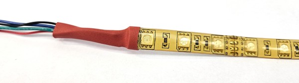
-
If needed, solder wires to the tabs on your LED strip, then wrap them in heat shrink tubing (Figure 4). Make sure you color-code the wires so you know which one is which. If your LED strip came with wires attached, you can skip this step.Figure 4. Wires soldered to an LED strip.
- Orient your Arduino and breadboard so they match the orientation in Figure 5.
- Place the three MOSFETs in the breadboard with the writing on the black side facing to your right and the large metal tabs facing to your left. Each MOSFET has three pins, and each pin should go in its own row.
- You will connect the three MOSFETs such that each one controls one color (red, green, or blue) on your strip. Decide which MOSFET will control which color. For each MOSFET:
- Connect the pin closest to the top of the breadboard (the MOSFET's "source") to the ground bus.
- Connect the pin closest to the bottom of the breadboard (the MOSFET's "gate") to an Arduino PWM pin (a pin with a "~" next to it). Our example code uses pins 3, 5, and 6 for red, green, and blue respectively.
- Connect the center pin (the MOSFET's "drain") to the corresponding wire from the LED strip.
- Put the switch in the breadboard so that each of the three pins is in its own row.
- Connect the center pin to the power bus on the right side of the breadboard.
- Connect the top pin to the positive wire from your 12 V power supply. (Use an adapter if needed, but do not plug your power supply into the wall yet.)
- Connect power to your circuit.
- Make sure the entire circuit has a common ground. The Arduino's GND pin, the negative wire from your 12 V power supply, and both breadboard ground buses should all be connected.
- Connect the 5 V pin from your Arduino to one of the breadboard's power buses (in Figure 5, this is the bus on the left). Make sure you do not connect the breadboard's two power buses to each other. This will short-circuit 12 V to 5 V and could damage your circuit.
- Connect the +12 V wire from your LED strip to the 12 V power bus on your breadboard (the right side in Figure 5).
- Plug your power supply into the wall but keep the power switch in the "off" (down) position for now.
- Plug your Arduino into your computer with a USB cable.
- If you see or smell smoke or if anything feels hot, immediately unplug both your power supply and the USB cable. You have a short circuit somewhere. Double check your entire circuit, paying particular attention to whether you have accidentally shorted 12 V to 5 V.
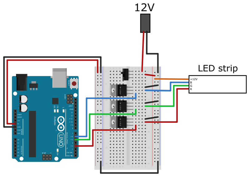 Figure 5. A breadboard diagram for connecting an analog RGB LED strip to an Arduino.
 - Download the led_strip_fade.ino example code and upload it to your Arduino. This code uses the Arduino's analogWrite command to set the brightness of each LED color between a value of 0 (off) and 255 (maximum brightness).
- Turn the power switch on the breadboard to the "on" (up) position. You should see your LED strip automatically fade through different colors! If your strip does not power on at all or does not change colors, double check all the connections on your breadboard, especially to the MOSFETs.
- Open the serial monitor in the Arduino IDE (Tools → Serial monitor) and watch the red, green, and blue values as they change. How do they correspond to the color of the LED strip?
- Try changing the fadeDelay variable in the code and see what happens.
- At least one of the color values (red, green, or blue) is always zero in this example code. What happens if you activate all three colors at once?
- Optional: How does the brightness of the LEDs correspond to the analogWrite value? If you set the brightness of a single color to 128 and leave it constant, does it appear half as bright as when it is set to 255?
/-/https/www.sciencebuddies.org/cdn/Files/20140/8/LED-strip-wires.jpg)
/-/https/www.sciencebuddies.org/cdn/Files/20141/8/RGB-LED-strip-breadboard.png)
Using a Sensor
After your LED strip is working, you should test your sensor separately. Remember that this makes it easier to find and identify any problems in your circuit.
- Save your LED code and open a new file.
- If you followed our circuit diagram in Figure 5, you should have plenty of space on the left side of your breadboard to connect one or more sensors. Connect your sensor to the Arduino and write a simple program to test its output—by controlling a single regular LED, for example, or by printing the sensor value to the serial monitor.
- Follow along with the appropriate tutorial(s) to test your sensors. Tutorial videos for the five sensors shown in Figure 2 (PIR, ultrasonic, potentiometer, microphone, and photoresistor) are listed below. If you purchased a sensor that is not listed here, you can check our How to Use an Arduino page to see if your sensor is listed, or you can look up another tutorial online.
/-/https/i.ytimg.com/vi/3gj_68ywod4/maxresdefault.jpg)
/-/https/i.ytimg.com/vi/n-gJ00GTsNg/maxresdefault.jpg)
/-/https/i.ytimg.com/vi/Wa8CjGsOFzY/maxresdefault.jpg)
/-/https/i.ytimg.com/vi/bMs5J4bJOD0/maxresdefault.jpg)
/-/https/i.ytimg.com/vi/XwJQJnY6iUs/maxresdefault.jpg)
- Think about how you will use your sensor in your project and where it needs to be positioned. For example, you might start testing an ultrasonic sensor just by waving your hand in front of it while it is sitting on a table. But if you want it to detect a person walking toward a room, it may need to be mounted on a wall. Depending on where you put your Arduino, you might need longer wires to connect the sensor to your breadboard. Make sure you test your sensor under these real-world conditions.
Making Your LED Strip React to a Sensor
So far you have one program that controls your LEDs and one program that takes a reading from your sensor. Now you need to combine them and make your LEDs react to your sensor. If you need help getting started, refer to these example programs for the five sensors we have discussed:
- PIR sensor
- Ultrasonic sensor (HC-SR04 and PING)
- Potentiometer
- Microphone
- Photoresistor
Note that the Arduino map function is very useful in some of these programs to convert the sensor's output from its original range (which can vary) to the range needed to control LED brightness (0 to 255).
You can change these programs as much as you want. If you are using multiple sensors, you may want to combine their programs. And if you are using a completely different sensor, you can write your own program! Remember that there is no right or wrong way to do this project—it all depends on the criteria you set for your design in the engineering design process.
After writing your program, make sure you test it. You may need to make changes to your code. For example, you might have to change a sensor threshold value or adjust the R, G, and B values to get the exact color(s) you want.
Once your design is finalized, you can impress your friends and family with your own smart RGB LED lighting system!
Ask an Expert
Global Goals
The United Nations Sustainable Development Goals (UNSDGs) are a blueprint to achieve a better and more sustainable future for all.
/-/https/www.sciencebuddies.org/cdn/Files/19752/5/E-WEB-Goal-09.png)
Variations
- Try this project with an individually addressable (digital) LED strip instead of an analog strip.
- The microphone example code in this project is just responding to loud sounds (like claps) and not to voice commands. Can you add a voice control module to your project and use command words to control the LEDs instead? Check out our Arduino Voice-Controlled Lamp project to learn more.
Careers
If you like this project, you might enjoy exploring these related careers:
/-/https/careerdiscovery.sciencebuddies.org/cdn/Files/1223/17/iStock-971549326.jpg)
/-/https/careerdiscovery.sciencebuddies.org/cdn/Files/1163/18/pexels-photo-1181472.jpg)
Contact Us
Our kits are developed in partnership with Home Science Tools®. If you have purchased a kit for this project, Home Science Tools® is pleased to answer any questions.In your email, please follow these instructions:
- Include your Home Science Tools® order number.
- Please describe how you need help as thoroughly as possible:
Examples
Good Question I'm trying to do Experimental Procedure step #5, "Scrape the insulation from the wire. . ." How do I know when I've scraped enough?
Good Question I'm at Experimental Procedure step #7, "Move the magnet back and forth . . ." and the LED is not lighting up.
Bad Question I don't understand the instructions. Help!
Good Question I am purchasing my materials. Can I substitute a 1N34 diode for the 1N25 diode called for in the material list?
Bad Question Can I use a different part?
Contact Support

/-/https/img.youtube.com/vi/s_-nIgo71_w/0.jpg)
/-/https/img.youtube.com/vi/dsvqypHoegI/0.jpg)
/-/https/img.youtube.com/vi/5ZjbIC0c7KM/0.jpg)