Abstract
Global warming, climate change, melting ice caps—these are all big events that have an impact our environment. What can we do to help reduce the impact? We can reduce, reuse, and recycle. What can cities do to help? Cities can eliminate waste by saving energy. Cities around the world are switching from incandescent traffic signals to LED traffic signals to save energy and money. That's because LEDs are more efficient than incandescent lamps, which means that LEDs produce more light compared to incandescent lamps for the same input power. So with LEDs, you get more for less! In this science project, you will learn how LEDs are used and why so many cities and countries are making the switch to LED technology.Summary
Michelle Maranowski, PhD, Science Buddies.
Edited by Steven Maranowski, PhD, Philips Lumileds Lighting Company.
The author would like to thank Thomas Goglio for building the stand.
Project updated by Ben Finio, PhD, Science Buddies
- LumiledsTM is a trademark of Philips Lumileds Lighting Company.
- Texas Advanced Optoelectronic Solutions® is a registered trademark of Texas Advanced Optoelectronic Solutions, Inc.
/-/https/www.sciencebuddies.org/cdn/Files/3300/5/Elec_img127.jpg)
Objective
The purpose of this science project is to learn about a key real-world application of light-emitting diodes (LEDs): the traffic signal. You will put together three simple circuits to study how efficient an LED is compared to a conventional incandescent lightbulb. You will then be able to determine which technology is the better choice for traffic signals.
Introduction
Our lives would be completely different without semiconductors. All integrated circuit (IC) chips are made out of semiconductors. ICs are in our cars, in airplanes, and in our kitchen appliances. But what is a semiconductor? A semiconductor is a material whose function falls somewhere between an insulator (like plastic) and a conductor (like copper). Semiconductors have the ability to conduct electricity under certain conditions, which leads to some interesting and useful devices, such as transistors and lasers. You can read more about the basics of electricity in the Science Buddies Electricity, Magnetism, & Electromagnetism Tutorial.
One semiconductor you've probably heard of is a light-emitting diode (LED), which is a semiconductor device that converts electricity into light. Current in semiconductors is carried by electrons (negatively charged) and holes (positively charged). An LED consists of a layer of electron-rich material next to a layer of hole-rich material. When a current is applied to the LED in a certain direction, the electrons move toward the holes and the holes move toward the electrons. When an electron and a hole meet, they create light. The wavelength, or color of the light, depends on the materials that are used for the layers and how electron-rich layer 1 is and how hole-rich layer 2 is.
/-/https/www.sciencebuddies.org/cdn/Files/3291/5/Elec_img120.gif)
Figure 1. Here are the two layers in the LED. When the two are joined, electrons and holes meet in the middle.
This engineering science project is an excellent example of how different areas of study intersect to solve a problem. For example, how can a city save energy and save money? It costs money to run city services, such as traffic signals. That's because making power costs money. How can a city save money on traffic lights? The answer is to convert from incandescent traffic signals to LED (light-emitting diode) traffic signals. A lightbulb, called an incandescent lamp, also converts electricity into light. However, an LED produces more light with less power than a regular lightbulb does. This means that LEDs are more efficient. The wall plug efficiency is defined as the ratio of optical output power of the device and the electrical input power (i.e., the efficiency of converting electrical power into optical power). Wall plug efficiency is a measure that is used to compare LEDs to each other and to other light-emitting devices, such as the incandescent lamp.
Additional LED advantages are that they are extremely rugged, can withstand shock and vibration, are compact, last longer, and do not radiate as much heat as incandescent lamps do. In fact, about 90% of the energy that is used to light up an incandescent lamp is lost to heat!
In addition to being a more environmentally friendly option than regular incandescent lamps, LEDs improve safety on the roads. Since LEDs are so bright compared to incandescent lamps and turn on faster, they are easier to see. An LED turns on nearly instantly, about 200 milliseconds faster than an incandescent lamp. This means that a car with LED brake lights will alert other drivers behind them that they are stopping 200 milliseconds sooner. At 65 miles per hour, this provides an extra 19 feet of stopping distance for drivers looking at the LED brake light.
/-/https/www.sciencebuddies.org/cdn/Files/3292/5/Elec_img121.jpg)
Figure 2. Shown is a green LED traffic signal.
In this engineering science project you will be measuring the wall plug efficiency of the LED and comparing that to the wall plug efficiency of an incandescent lamp. To do this, you will assemble three circuits to test for wall plug efficiency. The first circuit will be a constant-current circuit that applies constant current to the LED for however long you test. The second circuit will be a light-detection circuit. The light-detection circuit contains a light-to-voltage converter that monitors any changes in the brightness of the light coming from the LED and is proportional to the output power of the light source. The third circuit applies a voltage to an incandescent lamp. Have fun and remember that you are doing your part to help the environment.
Terms and Concepts
- Semiconductor
- Insulator
- Conductor
- Transistor
- Laser
- Light-emitting diode (LED)
- Diode
- Incandescent
- Wall plug efficiency
- Lumens
Questions
- What is a semiconductor? How many kinds of semiconductors are there?
- What is the difference between an incandescent lamp and a light-emitting diode?
- Can you confirm whether LEDs are a good choice for traffic signals?
- What other applications for LEDs can you find besides traffic signals?
Bibliography
- Science Buddies Staff. (n.d.). How to Use a Breadboard. Retrieved September 25, 2015.
To read more about various LED products, see some cool pictures of applications, and read interesting case studies:
- Philips. (n.d.). Philips Lighting Blog: LED. Retrieved July 17, 2020.
For a simple explanation of how LEDs work, read the following entries:
- Wikipedia Contributors. (2008). Light-emitting diode. Wikipedia: The Free Encyclopedia. Retrieved March 18, 2008.
- Harris, T. (2008). How Light Emitting Diodes Work. howstuffworks. Retrieved March 18, 2008.
For application notes and the data sheet on the LED constant-current driver, read:
- LED Supply. (2008). 7027 BuckToot. Retrieved April 23, 2014.
The data sheet for the light-to-voltage converter has complete specifications for the TSL250R, TSL251R, and TSL252R models. For this science project you will be using the TSL252R.
- AMS (2016, Mary 30). TSL250R, TSL251R, TSL252R Light-To-Voltage Optical Sensors. Retrieved March 29, 2018.
Materials and Equipment
Unless noted otherwise, the electronics parts for this project are available from Jameco Electronics.
Test Assembly
- Safety goggles
- Drill with ¾-inch drill bit
- Ruler
- Plywood, 8.5 inches x 11 inches, 1 inch thick
- Wood dowel, ¾ inches thick, 18 inches long
- Carpenter's glue
Constant-current Test Circuit
- Pigtail barrel jack adapter, part #2114600
- 12 V, 500 mA AC-DC power adapter, part #1940694
- 350 mA constant-current LED driver, part #2155891
- Alligator clip leads (10 pack), part #10444
- High-power white LED (3), part #2096843
- Digital multimeter. A variety of multimeters are available from Jameco Electronics. If you plan on doing more electronics projects in the future, it may be worth investing in a more expensive multimeter.
- Sunglasses
- Small piece of paper
Incandescent Lamp Circuit
- Mini incandescent lamp (3), part #141073
Light-detection Circuit
- TSL257-LF light-to-voltage converter, available from Digikey Electronics or Mouser Electronics. This part is not currently available from Jameco.
- Solderless breadboard, part #20601
- AA batteries (2 unused), part #198707
- 2xAA battery holder, part #216081
- Jumper wire kit, part #2127718
- 10 kΩ resistor (circuit only requires one, but sold in multiples of 10), part #691104
- Flashlight
Additional Items
- 2-inch clamps (2) (Home Depot part # 80002)
- Masking tape
- Ruler
- Lab notebook
- Graph paper
Disclaimer: Science Buddies participates in affiliate programs with Home Science Tools®, Amazon.com, Carolina Biological, and Jameco Electronics. Proceeds from the affiliate programs help support Science Buddies, a 501(c)(3) public charity, and keep our resources free for everyone. Our top priority is student learning. If you have any comments (positive or negative) related to purchases you've made for science projects from recommendations on our site, please let us know. Write to us at [email protected].
Experimental Procedure
Safety Note: Remember that you should never look directly at an LED when it is in operation. Wear your sunglasses.
Materials Note: The materials list for this project has been updated since it was originally written. Your parts might not look exactly like the parts shown in the pictures.
While there are a lot of instructions, don't let this concern you. Here is a brief explanation of each section and its purpose. This procedure is separated into five sections:
- Building the Test Assembly
- Building the Constant-current Test Circuit
- Building the Incandescent Lamp Circuit: In order to electrically test the LED against the incandescent lamp, you need to turn on the devices by applying a constant current and constant voltage respectively, which is why you first build the two circuits in sections 2 and 3.
- Building the Light-detection Circuit: In this section, you will build a circuit to quantify and compare the brightness of the light coming out of the LED and the incandescent lamp.
- Testing and Data Collection: Sections 4 and 5 detail how to test the LED and incandescent lamp in order to obtain your data.
Building the Test Assembly
- Build a test assembly so that the light from the LED can shine directly onto the open window of the light-to-voltage converter. The test assembly needs to dry overnight, so do this step first.
- Drill a hole in the 8.5-inch x 11-inch piece of plywood. Drill the hole along the longer side of the piece, about 1 3/4 inches in from the edge and centered. Be sure to wear your safety goggles.
-
Glue the wood dowel into the hole with the carpenter's glue. Make sure that the wood dowel is straight and perpendicular to the plywood. Let it dry overnight, ensuring the dowel won't move.
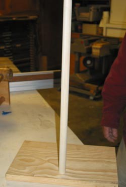
Figure 3. Here is the wooden stand from building the test assembly.
/-/https/www.sciencebuddies.org/cdn/Files/3295/5/Elec_img122.jpg)
Building the Constant-current Test Circuit
Assemble the constant-current LED test circuit as shown in Figure 4 and outlined in these steps.
- Plug the 12 V power adapter into a wall outlet.
- Plug the power adapter's barrel plug into the pigtail adapter.
- Use your multimeter to determine which wire of the pigtail adapter is positive, and which is negative. Set the multimeter to measure voltage and connect one probe to each wire of the pigtail adapter. If the voltage displays as negative, reverse the probes. Your multimeter's positive probe is now connected to the positive wire, and the negative probe is connected to the negative wire. Mark the wires (for example, with pieces of tape that you write on) so you can easily distinguish them.
- Use alligator clips to connect the pigtail adapter to the LED driver's "Vin" pins. Connect the positive pigtail wire to the "Vin +" pin (red wire) and the negative pigtail wire to the "Vin -" pin (black wire).
- Put your sunglasses on.
- Cover the back side of the LED board with a small piece of paper. This is important to prevent short circuits, because the back of the LED board is metal.
- Use alligator clips to connect the "Vout" pins of the LED driver to the LED. Look closely at the LED and you will see that it has pads labeled "+" and "-". Connect the "Vout +" pin of the LED driver (yellow wire) to a "+" pad on the LED, and the "Vout -" pin of the LED driver (blue wire) to a "-" pin on the LED.
- The LED should turn on as soon as you connect both pads. Be sure not to look directly at the LED. Looking directly at an LED can hurt your eyes.
- Note: Because the pads are so small, you may have a hard time connecting alligator clips directly to the LED board. If this is the case, get an adult to help you solder jumper wires to the "+" and "-" pads, and attach the alligator clips to those. If you try clipping directly to the board, remember to make sure the back side of the board is insulated with paper or electrical tape, so the alligator clips do not short together.
/-/https/i.ytimg.com/vi/ts0EVc9vXcs/maxresdefault.jpg)
/-/https/www.sciencebuddies.org/cdn/Files/7411/7/LED-constant-current-circuit.png)
Figure 4. Schematic for connecting the constant-current LED test circuit.
- The constant-current test circuit is now complete and you are ready to apply 350 mA to your traffic signal LED to do your experiment. But first, you will learn how to connect the incandescent bulb circuit. Disconnect both alligator clips from the pigtail connector, but leave the other parts of the circuit connected.
Building the Incandescent Lamp Circuit
Assemble the incandescent lamp test circuit as shown in Figure 5 and outlined in these steps.
- The pigtail adapter should already be connected to the power adapter from the previous section. Remember that you should have marked which wire was positive and which one was negative, but this actually does not matter for the incandescent lamp. Unlike LEDs (which only let current flow through in one direction), incandescent lamps let current flow through in either direction
- Use alligator clips to connect the pigtail wires to the two leads of the incandescent lamp. The lamp should light up. Disconnect the alligator clips from the pigtail adapter until you are ready to test the lamp.
/-/https/www.sciencebuddies.org/cdn/Files/7412/8/incandescent-bulb-circuit.png)
Figure 5. Schematic for connecting the incandescent lamp test circuit.
Building the Light-detection Circuit
-
The light-detection circuit is simple to make and consists of a light-to-voltage converter and a 10 kΩ resistor. Figure 6 shows an internal diagram of the light-to-voltage converter. When light hits the light-to-voltage converter it outputs a voltage that is proportional to the intensity of the light that is shining on it.
A circuit diagram shows a light-to-voltage converter wired in parallel with a resistor and connected to a circuit with an LED and battery.
Figure 6. This is an internal circuit of a light-to-voltage converter. (TAOS, Inc., 2006.)
- It is easy to build this circuit on a solderless breadboard. You can learn how to use a breadboard in the Science Buddies reference How to Use a Breadboard for Electronics and Circuits. You can follow the written directions to insert each component, and refer to the breadboard diagram in Figure 9.
- First, place two fresh batteries into the battery holder. Make sure the "+" symbols on the battery line up with the "+" symbols inside the battery holder. Connect the battery pack's red lead to the breadboard's power bus, and the black lead to the breadboard's ground bus.
-
The light-to-voltage converter is shown in Figure 7. It has three pins: ground (GND), power (VDD), and output (OUT).
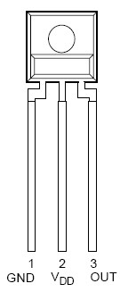
Figure 7. Light-to-voltage converter pin configuration. (TAOS, Inc., 2006.)
- Push the leads of the light-to-voltage converter into three separate rows of the breadboard.
- Use a jumper wire to connect the "VDD" pin of the light-to-voltage converter to the breadboard's power bus.
- Use a jumper wire to connect the "GND" pin of the light-to-voltage converter to the breadboard's ground bus.
- Connect one lead of the 10 kΩ resistor to the same row of the breadboard as the "OUT" pin of the light-to-voltage converter. Push the other end of the resistor into the breadboard's ground bus.
- The light-detection circuit is now complete. The output signal is the voltage drop across the 10 kΩ resistor. Check the voltage drop across the 10 kΩ resistor with the digital multimeter. Test the circuit by shining light on the open window of the light-to-voltage converter with a flashlight and see if you get a change in voltage across the 10 kΩ resistor. You should see a voltage between 1 and 3 V. When you cover the window of the light-to-voltage converter, you should see a voltage close to 0 V.
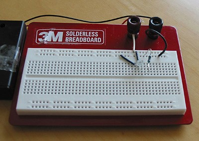
Figure 8. A picture of the light-detection circuit.
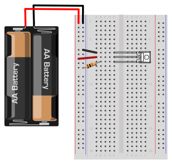
Figure 9. A breadboard diagram of the light detection circuit.
/-/https/www.sciencebuddies.org/cdn/Files/3298/5/Elec_img125.gif)
/-/https/www.sciencebuddies.org/cdn/Files/3301/5/Elec_img128.jpg)
/-/https/www.sciencebuddies.org/cdn/Files/3294/5/Elec_img118.jpg)
/-/https/www.sciencebuddies.org/cdn/Files/7413/7/light-detector-breadboard-diagram.png)
Testing and Data Collection
- Find an area in your house or school that is close to a wall socket for power and in a quiet area.
-
Clamp the breadboard to the wood dowel of the test assembly. You can use masking tape to hold the battery pack to the back of the breadboard so that it doesn't hang. This setup allows you to move the breadboard up and down. Also, make sure that the window of the light-to-voltage converter is facing the plywood base. This is where you will place the LED for testing.

A experiment to measure light intensity is setup with an LED shining beneath a light-to-voltage converter. The light-to-voltage converter is mounted in a breadboard which is clamped on one end to a wooden dowel. The wooden dowel is glued perpendicularly to a wooden block and a red LED is placed on the top of the wooden block. Alligator clips are attached to the leads of the LED and light-to-voltage converter to test the power output of each.
Figure 10. Here is the test setup.
-
Put on your sunglasses. Align the first LED directly underneath the light-to-voltage converter. Mark this position because you will have to place the LEDs and incandescent lamp in this position several times. Apply 350 mA to the first LED by re-connecting the constant current LED test circuit. Wait for 2 minutes, and take a voltage reading across the 10 kΩ resistor with the digital multimeter. You will notice that the voltage reading fluctuates. That's because the LED is heating up. In many applications, the voltage applied to the LED is pulsed on and off to minimize heating. For the purposes of this science project, heating effects are minimized by consistently taking the voltage measurement after 2 minutes. Make sure to mark each LED with 1, 2, or 3 so that you can tell them apart. The voltage across the resistor should be approximately 2.5 V. If the reading is 3 V, move the light-detection circuit farther away from the LED. If the reading is 3 V, then the light-to-voltage converter might be saturated. Saturated means that the photo detector can't detect any more light. If the voltage is close to 0 V, then move the light-detection circuit closer to the LED. Once you see that the voltage drop across the resistor is about 2.5 V, fix the breadboard in this position using the clamps. Note the voltage drop across the resistor in your lab notebook in a data table similar to the one shown below. This voltage reading is linearly proportional to the optical output power of the LED, see Equation 1.
Equation 1:
So you can say that the optical output power of the LED is equal to voltage drop across the resistor, multiplied by a linear factor, as shown in Equation 2.
Equation 2:
- Pout is the optical output power in watts (W).
- N is a linear factor.
- Vres is the voltage drop across the resistor in the light-detection circuit in volts (V).
- This project assumes that optical output power is the power collected by the detector. Using this assumption, N is the same for both the LED and the incandescent light sources, and the output power can be written in units of N in the data table (for example, write 0.75 N in the table). N cannot be determined easily, as it depends on the light emission vs. angle for each source.
- Measure the distance the LED is from the light-to-voltage converter with a ruler. Note the distance in your lab notebook, along with the voltage across the resistor. Use a data table like the one below.
-
Now measure the input electrical power to the LED using the digital multimeter. Power is defined in Equation 3 as:
Equation 3:
- Pin is the input electrical power in watts (W).
- Iin is the current going through the device is amperes (A).
- Vin is the voltage across the device in volts (V).
- Take the multimeter and measure the voltage across the LED. Note this value in your lab notebook. You are applying 350 mA to the LED. To get the input power to the LED, multiply these two numbers. Remember to multiply volts by amperes. So multiply the volts across the LED by 0.350 A. Record the input power to the LED in your lab notebook. Repeat steps 2–6 for LED #2 and LED #3.
- Now disconnect the LED circuit and reconnect the incandescent lamp circuit. Place the incandescent lamp in exactly the same position as the LEDs. Repeat steps 2–6 for each of the incandescent lamps. Record the data in your lab notebook.
-
Calculate the relative wall plug efficiency for each of the LEDs. Since you are not collecting all of the light at the light-to-voltage converter (some of the light goes off to the side), the calculation is relative. However, this measurement does mimic that of the real-world traffic light situation. When your eyes look at a traffic light they are not capturing all of the light; some of it is going off to the side of the device. Efficiency is derived by using the equations above, see Equation 4.
Equation 4:
-
Find the relative wall plug efficiency of the incandescent lamps using the incandescent lamp data in your lab notebook.
Distance LED is from Light-to-Voltage Converter Voltage Reading Across Resistor (volts) Output Optical Power (watts) Voltage across LED (volts) Current Going Through LED (amperes) Input Electrical Power (watts) Relative Wall Plug Efficiency LED #1 LED #2 LED #3 Average LED wall plug efficiency=
Distance Lamp is from Light-to-Voltage Converter Voltage Reading Across Resistor (volts) Output Optical Power (watts) Voltage across LED (volts) Current Going Through LED (amperes) Input Electrical Power (watts) Relative Wall Plug Efficiency Incandescent Lamp #1 Incandescent Lamp #2 Incandescent Lamp #3 Average incandescent lamp wall plug efficiency=
- Plot the efficiencies versus its respective device. What is the difference in efficiency between the LEDs and the incandescent lamps? Which one is higher? To calculate which device is more efficient, compare the relative wall plug efficiencies. When you compare the relative wall plug efficiency of the LED to the relative wall plug efficiency of the bulb (divide the LED WPE by the bulb WPE), the N factor will drop out. Which technology would you use for traffic signals?
/-/https/www.sciencebuddies.org/cdn/Files/3300/5/Elec_img127.jpg)
Ask an Expert
Global Goals
The United Nations Sustainable Development Goals (UNSDGs) are a blueprint to achieve a better and more sustainable future for all.
/-/https/www.sciencebuddies.org/cdn/Files/19755/5/E-WEB-Goal-12.png)
Variations
- Mimic an incandescent traffic signal by placing a red "filter" in front of the incandescent lamp. You can make a red filter with cardboard and red cellophane. How does the efficiency of the lamp change?
- Perform the same experiment using different-colored LEDs. For example, you can redo the project using yellow and green LEDs. Green LEDs are made from a different semiconductor. Compare these efficiencies with lamps that have yellow and green filters.
Careers
If you like this project, you might enjoy exploring these related careers:
/-/https/careerdiscovery.sciencebuddies.org/cdn/Files/1223/17/iStock-971549326.jpg)
/-/https/careerdiscovery.sciencebuddies.org/cdn/Files/1261/17/iStock-1250621440.jpg)
/-/https/careerdiscovery.sciencebuddies.org/cdn/Files/20162/5/SemiconductorProcessorHeroImage.jpg)
/-/https/careerdiscovery.sciencebuddies.org/cdn/Files/1233/17/unsplash-b28ac533a45f.jpg)
/-/https/careerdiscovery.sciencebuddies.org/cdn/Files/20167/5/IndustrialProdManager_KeyPhoto.jpg)

/-/https/img.youtube.com/vi/Vg6tvNNRlTA/0.jpg)
/-/https/img.youtube.com/vi/yYDSqsJqyxE/0.jpg)
/-/https/img.youtube.com/vi/JSEhXB07024/0.jpg)