Abstract
Imagine if you had to take medicine every time you ate, and you had to use a math formula to figure out how much medicine to take based on the nutritional makeup of the food, how you were feeling, and what activities you were planning to do. You might also need extra medicine throughout the day (even in the middle of the night) based on your blood glucose levels. People with diabetes who take insulin do this every day. They use finger sticks and blood glucose meters or a continuous glucose sensor to monitor their blood glucose throughout the day and take insulin to keep blood glucose within safe levels. Improvements in insulin pump and glucose sensor technology have led to smarter "hybrid loop" systems that can automatically adjust and administer insulin in response to changes in blood glucose levels. Because this type of system attempts to mimic the way the human pancreas works to regulate blood glucose, it is sometimes referred to as an artificial pancreas. In this project you will explore how these systems work by building a circuit that acts as a model of an artificial pancreas using two different liquids (tap water and distilled water instead of insulin and blood). You will try to fine-tune your circuit so it can quickly and safely adjust "blood sugar" to the right levels.
Summary
Previous experience with electronic circuits and an Arduino® is recommended.
A kit is available from our partner Home Science Tools®. See the Materials section for details.
Be careful when building your circuit. Short circuits can get hot.
/-/https/i.ytimg.com/vi/aRBPa3N70fk/maxresdefault.jpg)
Objective
Build a circuit that models an artificial pancreas by turning insulin delivery on and off in response to blood glucose levels.
Introduction
Scientists and engineers are often motivated to do their work in order to help people out. One area in which that motivation is readily apparent is in the field of biomedical engineering, where a great deal of research focuses on creating better medical devices and equipment. For people with diabetes, smarter insulin pumps and glucose monitoring technologies can make a big difference in how effectively they manage the disease. An artificial pancreas, or insulin pump that coordinates with a continuous glucose monitor, can automate some of the maintenance and monitoring of blood glucose, including increasing or decreasing insulin, to help people control their blood glucose more effectively. These systems can take over some of the decisions and calculations involved in insulin therapy and can monitor and respond to blood glucose 24/7, often making changes every few minutes. These systems can reduce the burden of managing diabetes and may lead to better overall management, but creating devices that can successfully manage blood glucose is a complex task and involves a large number of variables. The pancreas has a very complex biological role that has to be mimicked by a combination of electronics, chemistry, and biology. This project will allow you to explore some of the complexities engineers and scientists face as they develop artificial pancreas technologies.
First, let us step back for a moment and have a quick crash course (or a refresher if you are already familiar) on diabetes. The body uses a simple sugar, called glucose, as its primary fuel. We get glucose from the food we eat. Both table sugar (sucrose) and other types of carbohydrates, such as starch (found in large quantities in pasta and other grain-rich foods), are broken down by our bodies to make glucose. Because food can be broken down to make glucose, the level of glucose in a person's blood—which is commonly referred to as the blood glucose level—usually goes up after he or she eats. See Figure 1 for typical blood glucose level fluctuations for a person over the course of a day. Note that blood glucose is typically measured in milligrams per deciliter (mg/dL) in the US (other countries may use different units).
/-/https/www.sciencebuddies.org/cdn/Files/6179/11/glucose-levels-daily-fluctuations.jpg)
Glucose level graph shows spikes in blood glucose during breakfast, lunch and dinner, and a steady decrease in blood glucose after 8 p.m. Sucrose rich foods are highly available during lunch but availability decreases dramatically before dinner.
Figure 1. This graph shows how a person's blood glucose levels may change over the course of a day, and how eating a meal with lots of sugar (sucrose) can affect blood glucose levels. The y-axis shows blood glucose levels (in mg/dL). (Image credits: adapted from a figure by Jakob Suckale, Michele Solimena, Wikimedia Commons, 2011)
Like most of the chemicals in your blood, glucose must be tightly controlled. The level of glucose in your blood is regulated by insulin, a hormone made by the pancreas. When blood glucose levels rise after eating a meal, the pancreas releases insulin, which causes cells in the body (such as liver, muscle, and fat cells) to take up glucose, removing it from the blood and storing it (as glycogen) to use for energy later. When blood glucose levels start falling, the pancreas stops releasing insulin, and the stored glucose is used for energy. If blood glucose levels get too low, the pancreas may produce glucagon, a hormone that increases the levels. This process is how the pancreas and the hormones it produces regulate blood glucose levels. Watch this video to see how blood glucose levels can change over time for different people.
/-/https/i.ytimg.com/vi/JSFiOF7xGfE/maxresdefault.jpg)
However, in people with type 1 diabetes (which is caused by an autoimmune response, and was formerly known as juvenile diabetes), the pancreas no longer makes insulin. Without insulin, the blood glucose levels of a person with type 1 diabetes may go dangerously high, which is a condition called hyperglycemia. In type 2 diabetes—which makes up the vast majority of diabetes cases—a person has insulin resistance, which means the body does not respond effectively to insulin or the pancreas does not make enough insulin. Currently, a person with type 1 diabetes (and some with type 2 diabetes) must take insulin to treat the condition.
Insulin can help a person with diabetes control blood sugar, but taking insulin is not a once-a-day medicine, and figuring out how much insulin to take is not a simple task. Many things have an effect on insulin levels in a person's body, including exercise, stress, illness, and what and how much they eat. People with diabetes take insulin in a ratio to the carbohydrates they eat, in certain amounts when blood glucose is high, and in some form to provide background (basal) insulin all day long—even when they aren't eating. (Remember, the pancreas monitors and calculates all of this automatically in a person without diabetes.) Having blood glucose levels that are too high (hyperglycemia) or too low (hypoglycemia) can cause serious health problems. This leaves many type 1 diabetes patients constantly checking their blood glucose levels, calculating how their actions may affect their blood glucose, and adjusting their insulin doses to avoid dangerously high or low blood glucose. This video provides a brief overview of what this can be like for people with type 1 diabetes:
/-/https/i.ytimg.com/vi/CI8fpk-OKgQ/hqdefault.jpg)
As previously discussed, to take away the difficulties of managing type 1 diabetes, scientists and engineers continue to develop and improve insulin pumps, continuous glucose monitors (CGM), and other technologies that may contribute to an artificial pancreas. People with diabetes who take insulin take it in the form of insulin injections (using a needle) or infusions using an insulin pump, like the one shown in Figure 2. Insulin pumps are typically small, about the size of a cell phone. Some pumps work with a continuous glucose monitor, a separate sensor a person wears that detects the amount of glucose in the persons' blood and offers an updated reading every few minutes. When integrated, an insulin pump can use the CGM'S data to make decisions about how much insulin to give. This might mean temporarily increasing basal insulin, administering a bolus of extra insulin, or temporarily reducing or shutting off basal insulin.
Systems like this may be referred to as a form of loop. In a hybrid loop system, the pump may automate adjustments to some insulin delivery, but the person with diabetes still has to enter information about the amount of carbohydrates being eaten and other factors that may affect blood glucose. Users also have to program the pump with information about how much basal insulin they need every hour, how much insulin they require per gram of carbohydrate at different times of the day, and how much insulin they need to lower their blood glucose a certain amount (which is then used to calculate insulin corrections when blood glucose is high). A hybrid loop system can use this information, along with readings from a CGM and information about how long insulin is active in the body, to help manage insulin delivery and blood glucose levels. To see what it is like to use an insulin pump and continuous glucose sensor to manage type 1 diabetes, you can check out the video in the article by D. Grau in the Bibliography.
/-/https/www.sciencebuddies.org/cdn/Files/6194/12/Insulin-pump-infuser.jpg)
Figure 2. This picture shows an insulin pump attached to a person's body to infuse specific amounts of insulin.
The following video will give you a basic understanding of the goals of an artificial pancreas and the path to making one. Since this is a rapidly progressing field, you should do your own internet search to see what the current status of the research is.
/-/https/i.ytimg.com/vi/bOMtXCp_MCU/maxresdefault.jpg)
Now that you have a better understanding of type 1 diabetes and what an artificial pancreas is, you may be wondering how you can experiment with something related to insulin pumps or artificial pancreas technology for a science fair project. In this project, you will experiment to see how an artificial pancreas can automate insulin delivery in response to blood glucose levels by building a simplified model of an artificial pancreas. Your model will use two different liquids to represent blood and insulin: distilled water and tap water. Instead of measuring glucose content of the liquids, you will measure their electrical conductivity by building a circuit that outputs a voltage.
Distilled water is not very conductive. In your model, it will represent blood with high sugar content, which will cause the circuit to output a high voltage. Tap water is much more conductive, so when you add it to distilled water, the conductivity increases. This means you can use tap water to represent insulin in your model. When you add it to distilled water, the conductivity will increase, and the circuit's output voltage will drop, corresponding to a decrease in blood sugar in the model. Table 1 summarizes what happens in the real physical system (the human body) and what is used to represent the same parameters and behaviors in the model.
| Human Body | Artificial Pancreas Model |
|---|---|
| Blood | Distilled water |
| Insulin | Tap water |
| Blood glucose levels | Voltage |
| Adding insulin to blood with high glucose levels causes the glucose levels to decrease | Adding tap water to distilled water causes the voltage to decrease |
| Eating carbohydrates causes blood glucose levels to increase | Adding more distilled water causes the voltage to increase again |
You will use an Arduino to build your artificial pancreas model. An Arduino is a type of programmable microcontroller, which is sort of like a little computer that you can program to interact with electronic circuits. The Arduino can take readings from sensors and take actions based on the readings. In this case, the Arduino will read the voltage from a conductivity sensor placed in water and use that information to decide whether to turn a pump on or off. Turning the pump on will add "insulin" (tap water) to bring the "blood glucose" (voltage) levels down. This process of controlling a parameter (blood glucose/voltage) using sensor readings is called feedback control. Feedback control is a very important topic in engineering. It is used in everything from temperature control in ovens and thermostats to motion control in robots, airplanes, and autonomous cars.
For example, you might set the thermostat in your house to 70°F in winter. The thermostat measures the air temperature in your house. If the temperature is below 70°F, it will turn the heat on. If the temperature goes above 70°F, it will turn the heat off. Ideally, you would want your house to warm up quickly if it is cold (you do not want it to take all day to get to 70° if it is only 60° to start with). You also want to avoid overshoot, or going too far past your desired temperature. It would be annoying if your house first heated up to 80° before cooling back down to 70°. The same concept applies to blood glucose levels for people with diabetes. Blood glucose levels that are too high or too low can both be dangerous. When a person with diabetes injects insulin, ideally they want their blood glucose levels to quickly return to normal levels, without going past that level and going too low before stabilizing. Keep in mind that insulin does not immediately reduce blood glucose. Some insulins work over a period of hours. Understanding this timing is very important to insure someone doesn't receive too much insulin and is an important consideration for scientists as they develop the algorithms used by artificial pancreas systems. The model that you will build in this project generally responds to changes very quickly, within a few seconds, but it is important to remember that real feedback control systems can take much longer depending on the physical system that is being controlled. Heating (or cooling) a house and controlling blood glucose are both examples of systems that can take several hours to respond.
It is very important for an artificial pancreas to have a well-designed feedback control system to keep blood glucose levels in a safe range. In this project, you will follow instructions to build a basic artificial pancreas model with an Arduino. You will then try to edit the code to improve your feedback loop to get a better response. This is an open-ended project that follows the engineering design process. You can read more about the engineering design process and the difference between it and the scientific method in the Bibliography. If you are not familiar with an Arduino or working with circuits, several references in the Bibliography can help you with that as well. If you would like to know how exactly the circuit in this project works, see the following technical note.
Figure 3 shows the circuit you will build in this project. It has two main parts. First, a voltage divider measures the conductivity of the water. The voltage divider consists of one fixed resistor (R1) and a pair of electrodes immersed in water (R2). The input voltage (Vin) is the 5 V supply from the Arduino. The output voltage (Vout) is measured by one of the Arduino's analog (continuously variable) inputs. A voltage divider's output voltage is determined by Equation 1:
Next, the circuit has a pump that is controlled by one of the Arduino's digital (on/off) pins and a transistor. The transistor acts like an electronic valve that controls the current flowing through the pump. A transistor is necessary because the Arduino's digital pins can only supply a small amount of electrical current, about 20 milliamps (mA), while the pump requires about 500 mA. The transistor allows the pump to draw its power directly from the Arduino's 5 V supply, which can provide much more current than the individual digital pins.
/-/https/www.sciencebuddies.org/cdn/Files/6219/22/artificial-pancreas-circuit-diagram.png)
Circuit diagram showing a voltage divider consisting of resistors R1 (100 kilohms) and R2 (conductivity sensor) connected between 5 volts and ground, with the output connected to Arduino in A0. Arduino digital pin 11 is connected to the gate of a MOSFET with its source connected to ground and its drain connected to a pump which is powered from 5 volts.
Figure 3. Circuit diagram for the artificial pancreas model.
Example code for the Arduino is provided in the project's procedure. It provides a simple on/off control loop. It measures the voltage from the voltage divider using the Arduino's analogRead function. This function returns a number between 0 and 1023*. If the measured value is above a certain threshold (e.g., "blood sugar" is too high in the model), the code turns the pump on using the digitalWrite function. When the measured value drops below the defined threshold, the code turns the pump off.
* This is because the Arduino's analog-to-digital converter is 10-bit, meaning it can store 210 possible values. 210 is 1024, but the Arduino starts counting at 0, so the values range from 0–1023.
Terms and Concepts
- Sugar
- Glucose
- Blood glucose level
- Insulin
- Type 1 diabetes
- Hyperglycemia
- Type 2 diabetes
- Insulin pump
- Basal insulin
- Insulin bolus
- Continuous glucose monitor (CGM)
- Artificial pancreas
- Model
- Conductivity
- Circuit
- Voltage
- Arduino
- Microcontroller
- Sensor
- Feedback control
- Overshoot
- Engineering design process
- Voltage divider
- Resistor
- Electrode
- Analog
- Digital
- Transistor
- Current
- AnalogRead
- digitalWrite
- Hyperglycemia
- Hypoglycemia
Questions
- How do blood glucose levels typically change after a person eats a meal?
- What causes hypoglycemia and hyperglycemia?
- In what situations might a person with diabetes take an insulin shot?
- What is the difference between basal insulin and an insulin bolus?
- What do the different parts of the artificial pancreas model in this project represent in a real artificial pancreas system? How is the model different from the real thing? How is it similar?
- What is feedback control? What are some different systems where it is used? Why is it important?
- What is overshoot? When thinking about the delivery of insulin, why it is especially important to avoid overshoot?
Bibliography
Here are some useful resources on diabetes, blood glucose levels, insulin pumps, and artificial pancreases:
- Khan Academy. (n.d.). Blood sugar levels. Retrieved July 27, 2022.
- Beyond Type 1 (2018, June 29). WHAT IS TYPE 1 DIABETES?. Retrieved July 27, 2022.
- Juvenile Diabetes Research Foundation (JDRF). (2013, July 31). JDRF: Artificial Pancreas. Retrieved July 27, 2022.
- U.S. Food and Drug Administration (2018, August 30). What is the pancreas? What is an artificial pancreas device system?. Retrieved July 27, 2022.
- National Institute of Diabetes and Digestive and Kidney Diseases (2021, October). Artificial Pancreas. Retrieved July 27, 2022
- The Dale Tribe (2016, November 14). A DAY IN THE LIFE OF A TYPE 1 DIABETIC. Retrieved July 28, 2022.
You can check out these resources if you are just starting out with electronics:
- Taylor, C. (n.d.). Voltage, Current, Resistance, and Ohm's Law. SparkFun Electronics. Retrieved June 2, 2014.
- Science Buddies Staff. (n.d.). How to Use a Breadboard for Electronics and Circuits. Retrieved September 25, 2015.
- Science Buddies Staff (n.d.). How to Use a Multimeter. Retrieved March 25, 2022.
- Science Buddies Staff (n.d.). How to Use an Arduino. Retrieved March 25, 2022.
- Arduino (n.d.). Language Reference. Retrieved March 25, 2022.
Use these resources to learn about the engineering design process and its differences from the scientific method:
- Science Buddies Staff (n.d.). Engineering Design Process. Retrieved July 27, 2022.
- Science Buddies Staff (n.d.). Comparing the Engineering Design Process and the Scientific Method . Retrieved July 27, 2022.
Materials and Equipment 
Recommended Project Supplies
/-/https/www.sciencebuddies.org/cdn/Files/19915/12/SB_ARDNSTR_web__01473.jpg)
-
Electronics Kit for Arduino, available from our partner Home Science Tools®.
The kit includes the following parts that you need for this project:
- Arduino-compatible microcontroller board
- Note: This project will work with the Arduino UNO R3, UNO R4 Minima, UNO R4 WiFi, and compatible third-party boards.
- USB cable
- Breadboard
- Jumper wires
- Arduino-compatible microcontroller board
- You will also need to gather these items, not included in the kit:
- 5V peristaltic liquid pump (note: a 12V version of this pump is also available, but it requires an external power supply. The 5V version can be powered directly from your Arduino.)
- N-channel MOSFET
- 100 kΩ resistor
- Alligator clip leads
- Recommended: multimeter
- Bowls or food storage containers (2)
- Aluminum foil
- Tape
- Corks or packing foam
- Toothpick
- Tap water
- Distilled water
- Optional: food coloring
- Dish towels or paper towels
- Fine-tipped permanent marker
- Windows or Mac computer. See this page if you have a Chromebook. Your computer will need:
- Access to the Arduino IDE, either installed local version or web-based editor (note that Chromebooks can only use the web version). Watch this video for a comparison of the two options.
- USB port. The Science Buddies kit comes with a USB-A to B cable. The "B" end plugs into the Arduino and the "A" end plugs into your computer. You will need an adapter or different cable if your computer only has USB-C ports. Watch this video to learn about the different types of cables and adapters.
Disclaimer: Science Buddies participates in affiliate programs with Home Science Tools®, Amazon.com, Carolina Biological, and Jameco Electronics. Proceeds from the affiliate programs help support Science Buddies, a 501(c)(3) public charity, and keep our resources free for everyone. Our top priority is student learning. If you have any comments (positive or negative) related to purchases you've made for science projects from recommendations on our site, please let us know. Write to us at [email protected].
Experimental Procedure
- Build your conductivity sensor using two strips of aluminum foil and a piece (or pieces) of floating material. There are several options to build one (Figure 4). Make sure the sensor fits in the container you will use for water (Figure 5).
- The exact dimensions of the sensor do not matter. The general idea is that it should have two strips of aluminum foil, spaced apart by several inches, so they will sit at opposite ends of your water container.
- The sensor should float so that the amount of submerged surface area on the aluminum foil stays constant while you add water (the amount of submerged surface area will affect the conductivity reading).
- You will need to grab on to each piece of aluminum foil with an alligator clip, so make sure you leave part of each piece sticking up.
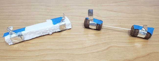
Figure 4. Two options for building a conductivity sensor. Left: a piece of packing foam with two strips of aluminum foil wrapped around its ends. Right: two corks with aluminum foil strips wrapped around them, spaced apart by a toothpick.
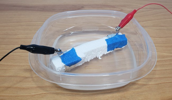
Figure 5. Conductivity sensor floating in a container of water with alligator clips attached to the aluminum foil. - Build the circuit. Figure 6 shows a "breadboard view" diagram. If you prefer to work with the circuit diagram, refer to Figure 3 in the introduction. Do not connect your Arduino to the USB cable yet. This will ensure that your circuit remains powered-down while you build it.
- Connect 5V on your Arduino to the power (+) bus on your breadboard.
- Connect the left and right power buses to each other.
- Connect GND on the Arduino to the ground (-) bus on your breadboard.
- Connect the left and right ground buses to each other.
- Put the MOSFET in the breadboard with the large metal tab facing to the left, and the writing on the front facing to the right. Each pin on the MOSFET should be in a different row of the breadboard.
- Connect the MOSFET's first pin on the left (when the writing is facing you, so the bottom-most pin in Figure 6) to Arduino digital pin 11.
- Connect the MOSFET's third pin to the ground bus.
- Put the 100 kΩ resistor into two different rows on the breadboard. Connect one end of the resistor to the power bus. Connect the other end to Arduino analog input pin A0.
- Use jumper wires and alligator clips to connect your conductivity sensor. Connect one end of the sensor to the same end of the resistor that is connected to pin A0. Connect the other end to the ground bus.
- Use jumper wires and alligator clips to connect the pump. Connect the tab labeled with a "+" to the power bus. Connect the other tab to the middle pin of the MOSFET.
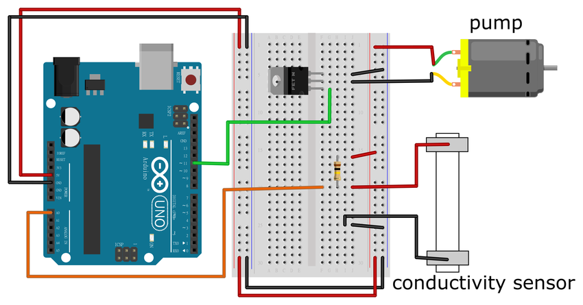
Figure 6. A breadboard diagram of the artificial pancreas model circuit. Click here to open a larger version of the diagram. - Before you continue, you will need to calibrate your conductivity sensor. Fill one of your containers about halfway with distilled water. Place your conductivity sensor in the container. Make sure it floats. You may need to adjust the alligator clips.
- Temporarily disconnect one alligator clip from the pump so it does not turn on during the calibration process.
- Plug one end of the USB cable into your Arduino and the other end into your computer. This will power up the Arduino and provide power to your circuit. If you have previously uploaded a different program to the Arduino, that program will start running automatically, but that is OK for now (which is why you disconnected your pump, just in case the Arduino code turns on pin 11). There are two different ways to take the calibration reading. Using a multimeter is not required, but it can be more convenient since you do not need to use a computer.
- If you have a multimeter available, set it to measure DC voltage and connect it to the circuit as show in Figure 7.
- Connect the multimeter's black probe to the ground bus and connect the red probe to the breadboard row that is connected to Arduino pin A0.
- Record the voltage reading. Convert it to an equivalent analogRead value by dividing it by 5, then multiplying by 1023 and rounding (for example, if your reading is 4 volts, the value would be 4/5×1023 = 818.4, which rounds to 818).
- If you do not have a multimeter available, download the calibration code to your computer. Then upload it to your Arduino. In the Arduino IDE, select Tools→Serial Monitor. The code will print out the analogRead value from the conductivity sensor. The value might fluctuate slightly. This is OK. Record the average value over a period of a few seconds.
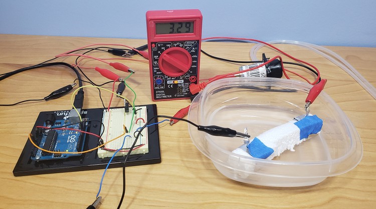
Figure 7. Multimeter connected to measure voltage from the conductivity sensor. - If you have a multimeter available, set it to measure DC voltage and connect it to the circuit as show in Figure 7.
- Fill your other container about halfway with tap water. Optionally, add a few drops of food coloring to make it easier to distinguish from the distilled water. Remove your conductivity sensor from the container with distilled water, dry it off with a towel, place it in the tap water, and the calibration procedure in step 5.
- The values you recorded in steps 5 and 6 are the maximum and minimum "blood sugar" values in your model. This can be a voltage (between 0 and 5 volts) or a number between 0 and 1023 (from the analogRead) function. To be clear, your Arduino code will use the number between 0 and 1023, not a number between 0 and 5, so if you measured a voltage, you need to convert it to the 0 1023 range as described in step 5. The "high" value corresponds to pure distilled water, and the "low" value corresponds to pure tap water. When you mix tap water and distilled water, you will get a number somewhere in between those two values. Your goal is to start the conductivity sensor out in a container of pure distilled water (which represents high blood glucose). Your code will measure the voltage from the conductivity sensor and automatically turn on the pump to start adding tap water to the container (to simulate adding insulin). This will cause the voltage to start dropping. When the voltage drops below a certain threshold that you define, the code will automatically turn the pump off. This models the behavior of an artificial pancreas, which would monitor blood glucose levels and apply insulin until glucose levels dropped (or were predicted to drop) to an acceptable level. Remember that your system is a model and responds to changes very quickly (within a few seconds), whereas changes in blood glucose levels can take much longer.
- Before you continue, you need to make sure you know which way water flows in your pump. Place both ends of the pump's tubing in the container with distilled water. Use alligator clips and jumper wires to connect the pump's electrical tabs directly to 5V (+) and GND (-) on your breadboard (the tab labeled "+" on the pump should go to 5V). This will turn the pump on. One at a time, carefully lift each of the pump's tubes out of the water. Watch closely to observe the direction of water flow (which tube has water dripping out of it?). Use a marker to draw arrows in the direction of water flow for each tube (Figure 8). Note that if you reverse the connections between 5V and GND, water will flow in the opposite direction. When you are done, disconnect the pump's negative wire from the GND pin.
- Leave the pump's outlet tube in the container of distilled water and place the inlet tube in the container of tap water.
- Remove the conductivity sensor from the container of tap water, rinse it off with some distilled water, and put it back in the container of distilled water.
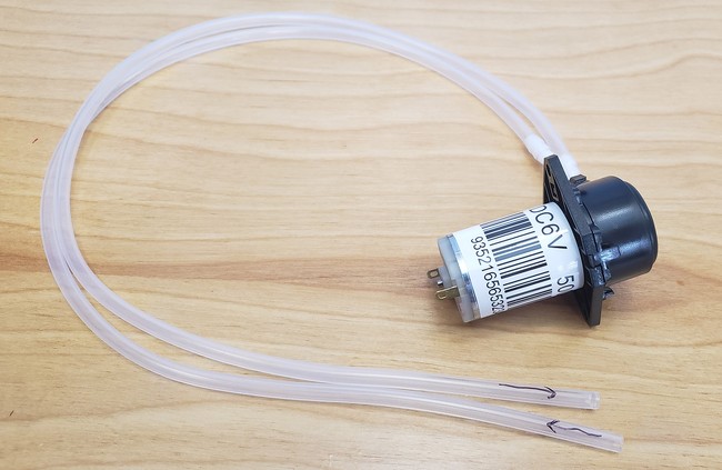
Figure 8. Arrows labeling the direction of water flow in the pump. - Download the example code. Read through the commented code and make sure you understand how it works. Choose a value for the "threshold" variable, the point at which you want the pump to turn off. Remember that this should be between the minimum and maximum values you recorded earlier (using the 0–1023 scale, not the 0–5 voltage scale). For example, if you recorded a minimum value of 200 and a maximum value of 800, you could set the threshold for the pump to turn off at 300. Upload the code to your Arduino and make sure you have the serial monitor open.
- Reconnect the pump's negative wire to the middle pin of the MOSFET on the breadboard. The pump should start right away, pumping tap water into the container with distilled water (Figure 9). As it pumps, use the pump's outlet tube to gently stir the distilled water container. This will help evenly distribute the tap water throughout the container. Watch the output on the serial monitor, and/or your multimeter reading if you have it connected.
- Does the pump turn off once the value reaches your defined threshold?
- Does the value keep changing after the pump turns off?
- If your pump does not turn on at all, unplug the USB cable from your Arduino. Double check your wiring, especially the connections to the MOSFET, since it controls the pump.
- If your pump never turns off, unplug the USB cable from your Arduino.
- Double check your wiring, especially the connections between the resistor, conductivity sensor, and analog input pin.
- Make sure the value you chose for the "threshold" value makes sense, as described in step 9.

Figure 9. The experimental setup, with the pump arranged to pump tap water into the container of distilled water. - Continue to stir the water for a minute or so after the pump turns off. Once you are confident the pump is staying off, disconnect the USB cable from your Arduino. This will stop it from printing data to the serial monitor.
- (Note: the instructions in this step are for a Windows computer. You will need to figure out how to do it if you are using another operating system). Click in the serial monitor and press CTRL+A to select all of the data. Press CTRL+C to copy it, and then open a .txt file in a program like Notepad and paste the data in. Save this file.
- You will need to import your data into a spreadsheet program like Microsoft Excel® or Google Sheets®. Most spreadsheet programs can import text files and split the data into different columns. For example, Excel can import text files using a "delimiter," a special character (like a tab or a space), to indicate a new column. Import your data so you have the time in one column and the analog reading in a separate column.
- Make a graph of your sensor reading (y axis) vs time (x axis).
- How quickly does your sensor reading reach the threshold value after the pump initially turns on?
- Does the sensor reading overshoot, or go past, the threshold value?
- Where does the sensor reading eventually stabilize?
- Now it is time to apply the engineering design process and iterate to improve your model. Look at the Arduino code and think of ways to improve it. How can you get to the threshold value quickly without overshooting too much? This is an open-ended problem. Here are some suggestions to get you started.
- You can control the pump's speed using the analogWrite command. analogWrite accepts a value between 0–255 that corresponds to the pump's speed (e.g., 0 is off, 127 is about half-speed, and 255 is full-speed). What happens if you run the pump at a lower speed?
- You could try a different type of feedback control instead of basic on/off control. For example, instead of running it a constant speed, a proportional controller changes the pump's speed based on the measurement error, or the difference between the target sensor reading and the actual sensor reading. In other words, when the error is large (the actual reading is very far away from the target reading), the pump will run faster. As the error gets smaller, the pump will start to slow down.
- Advanced students can look up other types of control like proportional-integral-derivative (PID) control, which involves more advanced mathematical functions and calculus.
- Try editing the Arduino code, re-uploading it, and testing your model again. In between tests, rinse and dry your containers and conductivity sensor. You should start out with fresh distilled water each time.
- Compare your new graph of voltage vs. time to your previous graph. It may help to plot them on the same axes, with the x-values shifted if needed so the points where the pump starts align with each other.
- Remember that your system is a model of an artificial pancreas, where the sensor reading (voltage) represents blood glucose levels. Think back to the information about diabetes in the introduction. What would you need to consider when designing a real artificial pancreas? What kind of response (the shape of the voltage vs time graph) would be ideal for a person with diabetes? What are the differences in how insulin works (and how long it takes) compared to your model? What challenges do these differences create? Your model turns insulin on and off, but what happens if blood glucose levels end up too low (overshoot) and/or continue to drop? How can an artificial pancreas address this?
/-/https/www.sciencebuddies.org/cdn/Files/18820/10/artificial-pancreas-circuit-electrodes.jpg)
/-/https/www.sciencebuddies.org/cdn/Files/18821/10/conductivity-sensor-water.jpg)
/-/https/www.sciencebuddies.org/cdn/Files/7660/23/artificial-pancreas-breadboard-diagram.png)
/-/https/www.sciencebuddies.org/cdn/Files/18822/10/artificial-pancreas-multimeter.jpg)
/-/https/www.sciencebuddies.org/cdn/Files/18824/10/artificial-pancreas-experiment-setup.jpg)
Troubleshooting
For troubleshooting tips, please read our FAQ: Dealing with Diabetes: The Road to Developing an Artificial Pancreas.
Ask an Expert
Global Goals
The United Nations Sustainable Development Goals (UNSDGs) are a blueprint to achieve a better and more sustainable future for all.
/-/https/www.sciencebuddies.org/cdn/Files/19746/5/E-WEB-Goal-03.png)
Variations
- Pour more distilled water into your container after the pump has turned off. Does the pump automatically turn back on again? You could also automate this process by adding a second pump and another container of distilled water. This can represent blood glucose levels rising due to a person eating.
- If you find it annoying to stir by hand, use a motor and build something to stir the water automatically. The motor can be controlled with your Arduino but note that if you connect multiple pumps and motors to your Arduino, they will require an external power supply.
- If you are interested in building a real artificial pancreas, check out the following resources from the diabetes community:
Frequently Asked Questions (FAQ)
Careers
If you like this project, you might enjoy exploring these related careers:
/-/https/careerdiscovery.sciencebuddies.org/cdn/Files/979/18/pexels-photo-3912962.jpg)
/-/https/careerdiscovery.sciencebuddies.org/cdn/Files/1223/17/iStock-971549326.jpg)
/-/https/careerdiscovery.sciencebuddies.org/cdn/Files/1107/19/pexels-photo-3938023.jpg)
/-/https/careerdiscovery.sciencebuddies.org/cdn/Files/4853/17/iStock-183716510.jpg)
/-/https/careerdiscovery.sciencebuddies.org/cdn/Files/1582/17/pexels-photo-4427557.jpg)
/-/https/careerdiscovery.sciencebuddies.org/cdn/Files/19471/5/pharmacy-technician-explaining.jpg)
/-/https/careerdiscovery.sciencebuddies.org/cdn/Files/19459/5/technician-repairing-operating-microscope.jpg)
/-/https/careerdiscovery.sciencebuddies.org/cdn/Files/19477/4/nurse-practioner-holding-hands-patient.jpg)
Contact Us
Our kits are developed in partnership with Home Science Tools®. If you have purchased a kit for this project, Home Science Tools® is pleased to answer any questions not addressed by the FAQ above.In your email, please follow these instructions:
- Include your Home Science Tools® order number.
- Please describe how you need help as thoroughly as possible:
Examples
Good Question I'm trying to do Experimental Procedure step #5, "Scrape the insulation from the wire. . ." How do I know when I've scraped enough?
Good Question I'm at Experimental Procedure step #7, "Move the magnet back and forth . . ." and the LED is not lighting up.
Bad Question I don't understand the instructions. Help!
Good Question I am purchasing my materials. Can I substitute a 1N34 diode for the 1N25 diode called for in the material list?
Bad Question Can I use a different part?
Contact Support

/-/https/img.youtube.com/vi/v0oaTHb2u0Y/0.jpg)
/-/https/img.youtube.com/vi/1_jAj5GAuZ0/0.jpg)
/-/https/img.youtube.com/vi/P6PGedCKrUM/0.jpg)