Abstract
The practice of "belly breathing" has been linked to improve mood, relaxation, and even have physical benefits like lowering your heart rate when compared to chest breathing. However, most of the time, we do not think about breathing—our bodies do it automatically. How do you know if you are belly breathing instead of chest breathing? How can you practice and get better at it? In this project you will build your own device to provide visual feedback about how a person breathes, then see if it can help train volunteers to use belly breathing more frequently.
Summary
Previous experience with Arduino or willingness to learn. See our How to Use an Arduino tutorial.
A kit is available from our partner Home Science Tools®. See the Materials section for details.
No issues
/-/https/i.ytimg.com/vi/WDRokF_ZW9A/maxresdefault.jpg)
Objective
Build a device that provides visual feedback to users about their relative amounts of belly and chest breathing, then see if using it can help people improve their breathing.
Introduction
Belly breathing, also called abdominal breathing or diaphragmatic breathing, is the process of taking deep breaths so your stomach expands and your lungs inflate fully. You do this using your diaphragm, a muscle at the base of your lungs. When you inhale, your diaphragm contracts and moves down, creating space for your lungs to expand and fill with air. When you exhale, your diaphragm relaxes and moves upward, pushing the air out of your lungs.
This is in contrast to chest breathing, also called thoracic breathing or shallow breathing. When chest breathing, you only take shallow breaths using the muscles in your rib cage. Your chest expands more than your stomach, and your lungs do not inflate fully.
Watch the following video to learn about some of the benefits of belly breathing and how to practice it. Make sure you watch the entire video, since toward the end it explains what happens inside your body.
/-/https/i.ytimg.com/vi/g2wo2Impnfg/maxresdefault.jpg)
As shown in the video, you can practice belly breathing simply by putting one hand on your chest and one hand on your stomach. When you inhale, try to make sure the hand on your chest stays as still as possible while the hand on your stomach moves. You can do this in standing, sitting, or lying-down positions. Watching your hands move is a very simple technique for measuring the relative amounts of belly and chest breathing.
What if you could quantify this motion, record it, and provide some other form of visual feedback about your breathing? There are a variety of medical and personal fitness devices that can track vital signs or biometrics, such as your heart rate (the number of times your heart beats per minute) and your respiration rate (the number of breaths you take per minute). However, most of these devices only measure respiration rate and cannot simultaneously measure relative amounts of chest and belly breathing.
In this project, you will build your own device that can simultaneously measure chest and belly breathing (Figure 1). The device has two straps with built-in stretch sensors that you can wear around your chest and belly. The sensors measure how much your chest and belly expand when you breathe. The sensors are connected to an Arduino® which measures their output. The Arduino lights up two sets of LEDs, one for the chest and one for the belly (Figure 1 inset), proportionally to the amount of stretch. This provides you with visual feedback about your relative amounts of chest and belly breathing. Your goal is to light up as many of the "belly" LEDs as possible when breathing, while lighting up few or none of the "chest" LEDs (just as you would want the hand on your belly to move while the hand on your chest stays still).
/-/https/www.sciencebuddies.org/cdn/Files/19381/9/arduino-breathing-monitor.jpg)
Figure 1. A picture of the setup with a close-up inset of the Arduino circuit. As the chest strap stretches, more of the green LEDs will light up. As the belly strap stretches, more of the blue LEDs will light up.
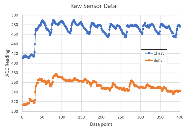
In addition to providing real-time feedback with LEDs, you can also record and graph the sensor data. Figure 2 shows sample data recorded during a period of chest breathing. Note how the amplitude changes for the chest sensor reading are larger than the changes for the belly sensor.
The y-axis for the graph does not show an amount of "stretch" directly. It shows the Arduino's analog-to-digital converter (ADC) value. The ADC converts an analog voltage between 0–5 V to a digital value between 0 and 1,023. Since you only care about relative amounts of chest and belly breathing for this project, you do not need to convert the ADC values to an actual stretch distance.
/-/https/www.sciencebuddies.org/cdn/Files/19383/9/chest-breathing-data-example-1.png)
A graph titled 'Raw Sensor Data.' The x axis of the graph is 'data point' and the y axis is 'ADC reading.' The graph shows two oscillating curves, one for the chest sensor and one for the belly sensor. The chest sensor has much larger-amplitude oscillations since the data was recorded during a period of chest breathing.
Figure 2. Example sensor data recorded during a period of chest breathing.
Each stretch sensor is made from a conductive rubber cord. When the conductive rubber stretches, its resistance increases. However, the Arduino cannot measure changes in resistance directly. It can only measure voltage. Your circuit will include a voltage divider for each sensor that will convert changes in resistance to changes in voltage. (See the SparkFun reference in the bibliography to learn more).
Your circuit will also include four calibration knobs called potentiometers—two for each sensor. The potentiometers will let you calibrate the sensors for different people. This is necessary since people are different sizes and their bodies will expand by different amounts when they breathe.
Terms and Concepts
- Belly breathing
- Abdominal breathing
- Diaphragmatic breathing
- Diaphragm
- Chest breathing
- Thoracic breathing
- Shallow breathing
- Vital sign
- Biometrics
- Heart rate
- Respiration rate
- Stretch sensor
- Arduino
- Analog-to-Digital Converter (ADC)
- Voltage divider
- Potentiometer
Questions
- What is the difference between belly breathing and chest breathing?
- From a physical and mental health perspective, how do belly breathing and chest breathing compare?
- How can you practice belly breathing?
- What are some ways you could provide visual or other sensory feedback to a person practicing belly breathing, instead of having them watch their hands?
Bibliography
- Learning diaphragmatic breathing. Harvard Medical School. Retrieved January 12, 2023.
- Finio, B. (n.d.). How to Use an Arduino. Science Buddies. Retrieved January 30, 2023.
- Lindblom, J. Voltage Dividers. SparkFun Electronics. Retrieved January 30, 2023.
Materials and Equipment 
Recommended Project Supplies
/-/https/www.sciencebuddies.org/cdn/Files/19915/12/SB_ARDNSTR_web__01473.jpg)
Electronics supplies are available from many vendors in different quantities. If you plan on doing more electronics projects in the future, sometimes it is more cost-effective to buy cheap parts like LEDs and resistors in bulk instead of buying them individually. The table below offers several options for where you can get the supplies from this project (not all parts are available from all vendors). Many of the parts you need to get started are also available in the Electronics Kit for Arduino, available from our partner Home Science Tools®. Note: This project will work with the Arduino UNO R3, UNO R4 Minima, UNO R4 WiFi, and compatible third-party boards.
| Part | Quantity | Amazon | Adafruit | SparkFun |
|---|---|---|---|---|
| Arduino UNO or compatible board | 1 | Arduino UNO REV3 | Adafruit METRO 328 | SparkFun RedBoard |
| USB cable (type depends on board) | 1 | USB A to B cable | USB A to micro-B cable | USB A to mini-B cable |
| Full-sized breadboard | 1 | Full-sized breadboard | Full-sized breadboard | Full-sized breadboard |
| Solid jumper wire kit | 1 | Jumper wire kit | Jumper wire kit | |
| Male-male flexible jumper wires | 1 | Flexible jumper wires | Flexible jumper wires | Flexible jumper wires |
| Alligator clip leads | 4 | Alligator clip leads | Alligator clip leads | Alligator clip leads |
| 10kΩ potentiometers (breadboard compatible) | 4 | 10kΩ potentiometer | 10kΩ potentiometer | 10kΩ potentiometer |
| 1/4W 220Ω resistors | 10 | 1/4W 220 Ω resistors | 1/4W 220 Ω resistors | 1/4W 220 Ω resistors |
| 1/4W 4.7kΩ resistors | 2 | 1/4W 4.7k Ω resistors | 1/4W 4.7k Ω resistors | |
| Optional: 1/4W resistor kit (if you do not want to purchase resistors individually) | 1 | 1/4W resistor kit | 1/4W resistor kit | |
| Diffused 5mm green LEDs (or other color of your choice) | 5 | 5mm green LEDs | 5mm green LEDs | |
| Diffused 5mm blue LEDs (or other color of your choice) | 5 | Note: Adafruit has 3mm and 10mm blue LEDs but not 5mm | 5mm blue LEDs | |
| Optional: LED kit (if you do not want to purchase LEDs individually) | 1 | LED kit | LED kit | |
| Conductive rubber cord | 1 | Conductive rubber cord |
In addition to the electronic supplies, you will also need:
- Adjustable nylon buckle strap kit
- Sewing needle
- Thread
- Hobby knife
- Scissors
- Lighter
- Optional: Soldering iron
- Volunteers (at least 3)
- A table and chair
- A quiet, sedentary activity for your volunteers to do while sitting, like reading or looking at pictures. Avoid things like video games or watching videos.
- Small cardboard box that will fit over your Arduino and breadboard
- Timer or stopwatch
- Lab notebook
Disclaimer: Science Buddies participates in affiliate programs with Home Science Tools®, Amazon.com, Carolina Biological, and Jameco Electronics. Proceeds from the affiliate programs help support Science Buddies, a 501(c)(3) public charity, and keep our resources free for everyone. Our top priority is student learning. If you have any comments (positive or negative) related to purchases you've made for science projects from recommendations on our site, please let us know. Write to us at [email protected].
Experimental Procedure
Working with Human Test Subjects
There are special considerations when designing an experiment involving human subjects. Fairs affiliated with Regeneron International Science and Engineering Fair (ISEF) often require an Informed Consent Form (permission sheet) for every participant who is questioned. Consult the rules and regulations of the science fair that you are entering, prior to performing experiments or surveys. Please refer to the Science Buddies documents Projects Involving Human Subjects and Scientific Review Committee for additional important requirements. If you are working with minors, you must get advance permission from the children's parents or guardians (and teachers if you are performing the test while they are in school) to make sure that it is all right for the children to participate in the science fair project. Here are suggested guidelines for obtaining permission for working with minors:
- Write a clear description of your science fair project, what you are studying, and what you hope to learn. Include how the child will be tested. Include a paragraph where you get a parent's or guardian's and/or teacher's signature.
- Print out as many copies as you need for each child you will be surveying.
- Pass out the permission sheet to the children or to the teachers of the children to give to the parents. You must have permission for all the children in order to be able to use them as test subjects.
Assemble the Circuit
Assemble the circuit on your breadboard as shown in Figure 3. You do not have to use the exact layout shown in our breadboard diagram. If you prefer to lay out your circuit differently, you can follow the schematic in Figure 4. Figure 5 shows a picture of the assembled circuit (the same image that is inset in Figure 1). Larger versions of each image are available from the links in their respective captions. You can also download a Fritzing file that includes both the breadboard and schematic views. Fritzing is a free program for designing circuits. You can download it from Fritzing website.
You can also follow the list of connections below. Long, flexible jumper wires are better for making connections to the Arduino. Short, solid jumper wires are better for making connections on the breadboard. You will use alligator clips to connect the circuit to the chest and belly stretch sensors later; you do not need to connect them yet.
- Arduino 5V to breadboard power bus.
- Arduino GND to breadboard ground bus.
- Connect the two breadboard power buses.
- Connect the two breadboard ground buses.
- Connect ten LEDs to ten Arduino I/O pins, each with a 220 Ω current-limiting resistor to ground. LEDs numbered 1 through 10 in the circuit schematic are connected to Arduino pins 13 through 4 (counting down) respectively. The first five LEDs are green and the last five LEDs are blue.
- Connect four potentiometers. Each potentiometer should have its outer two pins connected to 5V and ground. The middle pins go to Arduino analog pins A1, A2, A3, and A4 respectively.
- Place two 4.7k Ω resistors on the breadboard. Connect one end of each resistor to 5V. Connect the other end of one resistor to Arduino analog pin A0, and the other end of the other resistor to Arduino analog pin A5.
- Connect one end of a long jumper wire to the same end of each resistor that is connected to an Arduino analog pin. You will use alligator clips to connect the free ends of these jumper wires to the stretch sensors later.
- Connect one end of two additional long jumper wires to ground. You will use alligator clips to connect the free ends of these jumper wires to the stretch sensors later.
/-/https/www.sciencebuddies.org/cdn/Files/19384/9/arduino-breathing-monitor-breadboard-diagram.png)
Figure 3. Breadboard diagram (click here for larger diagram version) for the Arduino breathing monitor circuit. Fritzing does not have a part in its library for conductive rubber cords, so resistors are used in the diagram to represent the chest and belly stretch sensors, which you will connect later.
/-/https/www.sciencebuddies.org/cdn/Files/19385/9/arduino-breathing-monitor-circuit-schematic.png)
Figure 4. Schematic for the circuit (click here for larger diagram version). The physical layout of the schematic does not match the physical layout of the actual parts on the breadboard, but it is electrically equivalent.
/-/https/www.sciencebuddies.org/cdn/Files/19386/9/arduino-belly-breathing-circuit.jpg)
Figure 5. The assembled circuit connected to an Arduino.
Make the Chest and Belly Straps
After assembling the circuit, you need to make the straps. Your goal is to make two straps like the one shown in Figure 6 by following the steps below. You may be able to build the strap just by looking at the picture, but you can also follow the detailed steps below. If you purchased a different buckle strap kit, your steps may vary.
/-/https/www.sciencebuddies.org/cdn/Files/19387/9/arduino-respiration-strap.jpg)
An adjustable buckle strap that looks somewhat like a belt. It forms a loop, but it has been cut in one location. The two cut ends are connected with a looped piece of rubber cord.
Figure 6. One of the completed sensor straps.
- Cut a piece of the strap about 5 feet long. It needs to be long enough to fit around an adult and have extra length for adjustments. It is better to make it too long initially and trim it later. If your initial piece is too short, you will need to start over.
- With adult supervision, use a lighter to heat seal the cut ends of the strap. This will melt the threads together and prevent them from fraying (Figure 7).
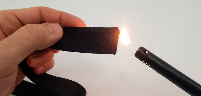
Figure 7. Using a lighter to heat seal the end of the strap. - Follow the instructions that came with your strap to install the buckles and adjustment clips on each end. Your end result should look like Figure 8.
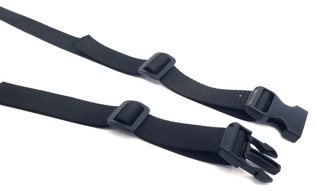
Figure 8. Strap with the buckles and adjustment clips installed on each end. - Clip the buckles together, then cut the strap closer to one of the buckles than the other, as shown in Figure 9. The exact location of the cut is not critical, but you do not want it to be centered halfway in between the buckles. If you do that, then when you put the strap on, the buckles will be on your back, and it will be very hard to adjust the strap yourself. If the cut is off to one side, then you will be able to reach the buckles on one side of your body.
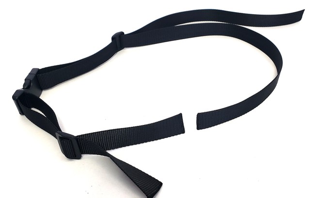
Figure 9. Buckle strap with a cut where you will attach the conductive rubber cord. - Use the lighter again to heat seal the two new cut edges.
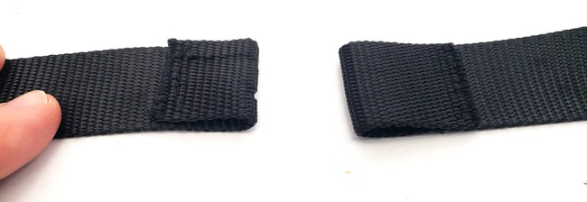
- Poke two holes in one end of the strap, as shown in Figure 10. The holes should be about 1 inch from the end and about 1/4 inch in from the edges. Your rubber cord needs to fit through the holes, so make sure it fits before you go to the next step. There are two different ways to make the holes:
- Use something sharp, like a pencil or hobby knife, to make and widen the holes. Then use the lighter to heat seal the holes.
- Use the tip of a soldering iron to melt the holes. Additional heat sealing is not necessary with this method.
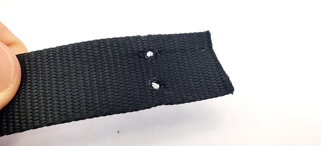
Figure 10. Buckle strap with two holes for the rubber cord. These holes were melted with a soldering iron. - Fold each end of the buckle strap back and sew it to itself to form a loop, as shown in Figure 11. For the strap with the holes, make sure the holes are pointing sideways (at the fold), not up or down. Make sure you leave an open space between the two sides, as shown in Figure 12 (do not completely sew the two sides to each other, leaving no gap). This is called a casing. You can find many sewing tutorials online if you need help doing this step.
The two ends of the buckle strap. Each end has been folded back onto itself by about 1 inch. The end of the strap is then sewn to the other part of the strap, creating a casing.
Figure 11. Top view of the two casings. Each one is about one inch long.
Figure 12. Side view of the casing, showing the gap. - Thread your conductive rubber cord through the casing that does not have holes in it. Then, thread each end of the rubber cord through one of the holes in the other casing, and pull it out the side. Figure 13 shows the result.
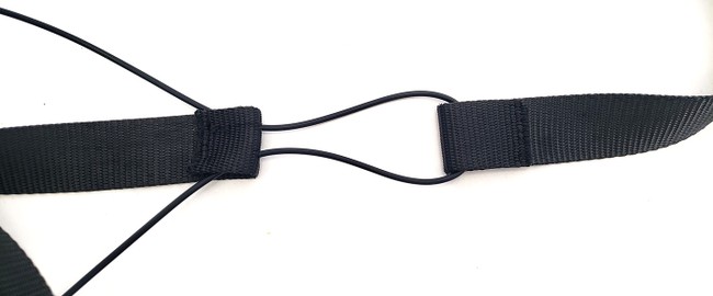
The rubber cord goes into the casing and out through one of the holes along the fold. Next it goes all the way through the casing on the other strap. Finally, it goes in the remaining hole in the first strap and out the side of the casing.
Figure 13. Rubber cord threaded through the two casings in the strap. - Pull the rubber cord as far as possible through the two holes, bringing the step straps close together. Then tie a knot in each end of the rubber cord, as close as possible to the strap, as shown in Figure 14. These knots will prevent the cord from slipping back through the holes. Cut the ends of the rubber cord, leaving about one inch of cord beyond each knot. You will attach alligator clips to these loose ends later.
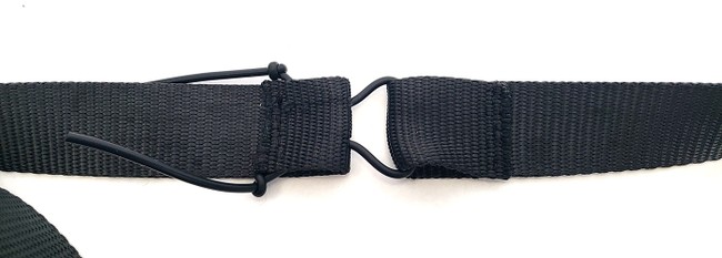
Figure 14. Rubber cord with a knot tied in each end to prevent it from slipping through the holes. - Pull the two ends of the strap away from each other. The knots should pull into the casing, but prevent the cord from slipping all the way through the holes, as shown in Figure 15. If the knots slip through the holes, you will need to tie bigger knots.
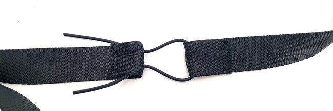
Figure 15. The strap after pulling the rubber cord tight. - Repeat the steps in this section to make your second strap.
/-/https/www.sciencebuddies.org/cdn/Files/19388/9/lighter-heat-seal-nylon-strap.jpg)
/-/https/www.sciencebuddies.org/cdn/Files/19389/9/buckle-straps-installed.jpg)
/-/https/www.sciencebuddies.org/cdn/Files/19390/9/buckle-strap-cut.jpg)
/-/https/www.sciencebuddies.org/cdn/Files/19391/10/buckle-strap-holes.jpg)
/-/https/www.sciencebuddies.org/cdn/Files/19392/9/buckle-strap-casing.jpg)
/-/https/www.sciencebuddies.org/cdn/Files/19393/10/buckle-strap-casing-side-view.jpg)
/-/https/www.sciencebuddies.org/cdn/Files/19394/9/rubber-cord-strap.jpg)
/-/https/www.sciencebuddies.org/cdn/Files/19395/9/rubber-cord-knots.jpg)
/-/https/www.sciencebuddies.org/cdn/Files/19396/9/strap-finished.jpg)
Upload Arduino Code and Test
Note: As of February 2023, there is a bug in the new version of the Arduino IDE (2.0) that does not allow you to copy and paste data from the serial monitor. You will need to copy and paste your data if you want to graph it later. For now, we recommend doing this project with Arduino IDE version 1.8, which is available for download from the "Legacy" section of the Arduino software page. If you have never used an Arduino before, we recommend going through at least the first seven tutorials on our How to Use an Arduino page before you continue.
- Download arduino_breathing_monitor.ino and save it on your computer.
- Read through all of the commented code so you understand how it works.
- Use alligator clips to connect the loose breadboard wires to the rubber cords, as in Figure 16. Make sure the alligator clips are connected as close as possible to the knots in the rubber cord, so they do not flop around too much.
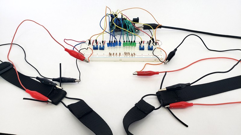
Figure 16. Completed circuit with the sensors attached with alligator clips. - Upload the program to your Arduino and open the serial monitor. You do not need to put the straps on for now—you will just test them by hand.
- Pick up the two ends of the chest strap by the rubber cord and gently pull on them, stretching them a centimeter or two, then release them. You should see the "Chest sensor" value in the serial monitor change. Pull on them a few more times. Write down the approximate minimum and maximum values that you see.
- Use potentiometer #1 (on the far right in Figure 16, assuming you followed our breadboard diagram) to adjust the "Chest ADC min" value so it is just below the minimum value you recorded in step 5.
- Use potentiometer #2 (second from the right in Figure 16, assuming you followed our breadboard diagram) to adjust the "Chest ADC max" value so it is just above the maximum value you recorded in step 5.
- Gently pull on the strap again. This time, you should see the five green LEDs light up proportionally to how far you pull the strap. When the rubber cord is not stretched at all, none of the LEDs should light up. When the cord is fully stretched, all five LEDs should light up.
- Repeat steps 5–8 for the belly strap, this time using potentiometers #3 (second from the left) and #4 (far left) to adjust the minimum and maximum values respectively. When you are done, you should be able to get both sets of LEDs to light up by pulling on the two straps.
/-/https/www.sciencebuddies.org/cdn/Files/19397/9/arduino-breathing-monitor-alligator-clips.jpg)
Practice Calibrating the Sensor
Now you will practice calibrating the sensor when a person is wearing it. You can test the sensor on yourself, or on a volunteer if you have one available. The volunteer should not be a person who is going to participate in your study, because this process "gives away" too much information. You need to get very comfortable with this process, because you will need to do it each time you hook someone up to your circuit when conducting human trials. Take your time and get used to setting it up.
- Sit in a chair next to your circuit.
- Put the chest and belly straps on as shown in Figure 17. The rubber cords should be in front so you can see them on your chest and belly. You may need to adjust the exact position of the straps for different body shapes and sizes, but the chest strap should approximately go just above your sternum, and the belly strap should be roughly across your belly button. The exact location is not critical. The two most important points are to make sure that the straps expand when you breathe, and that they do not slide around when you breathe. Make sure the alligator clips are long enough to reach the straps without pulling the circuit off the table. If needed, you can connect multiple alligator clips together end-to-end.
- Tighten the straps so they have a snug fit.
- When you exhale completely, the rubber cords should be in a mostly unstretched state, but you do not want the straps to slide down on your body. If the straps move around too much, tighten them slightly.
- When you inhale (puffing up either your chest or belly as much as possible), the rubber cords should stretch, but the strap should not restrict your breathing. If either strap feels too tight, loosen it slightly.
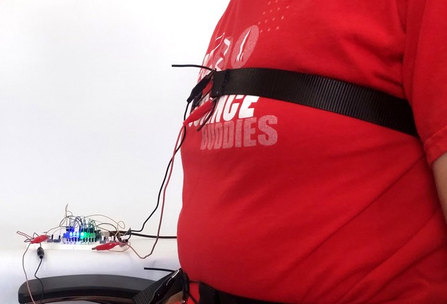
Figure 17. A person wearing the chest and belly straps while sitting next to the sensor. - If you are testing the sensors on yourself, position yourself so you can access the potentiometers and see the serial monitor on your computer. You will need to sit as still as possible during calibration since the sensors are very sensitive to movement. If you are testing on a volunteer, have them sit still in the chair.
- Now you will repeat the calibration process from the previous section, using breathing instead of pulling on the cords. Inhale and exhale while taking deep "chest breaths" (inflating your chest as much as possible and your belly as little as possible) or ask your volunteer to do so. Watch the serial monitor. Adjust the potentiometer such that the chest_ADC_min and chest_ADC_max values correspond to the minimum and maximum chest sensor readings. You can also watch the LEDs and adjust such that all the LEDs are off when you fully exhale and all the LEDs are on when you fully inhale.
- Repeat step 5 for the belly sensor and "belly breaths," where you inhale as deeply as possible while inflating your stomach, not your chest.
- Practice different types of breathing (breathing normally vs. belly breathing vs. chest breathing) for a few minutes and watch the LEDs. Make sure you hold still and ensure that the straps are adjusted so they do not slide around over time. If you shift to a different position (for example, slouching or leaning in the chair) or if the straps slide too much, you will need to re-calibrate.
- Take the straps off and repeat this entire section at least once. Even when you put the straps back on the same person, you need to re-calibrate them each time. It will be impossible to put the straps back in exactly the same place, and the person may be wearing different clothing or sitting in a slightly different position, etc. Make sure you are very comfortable with the calibration procedure before you continue.
/-/https/www.sciencebuddies.org/cdn/Files/19398/9/arduino-breathing-monitor-straps.jpg)
Conduct Human Trials
Now you are ready to conduct human trials and see if your device can help people improve their belly breathing.
- Develop a testing schedule for your volunteers. Your schedule should include a pre-test, at least 6 training sessions, and a post-test for each volunteer. Keep your volunteers on the same schedule for the training sessions (for example, 3 days a week for 2 weeks).
- Set up your test station. Position your computer monitor so the volunteers will not be able to see it. Cut one side out of a small cardboard box and place it over your circuit so the volunteers cannot see the LEDs during the pre-test. (You will remove this box for training later).
- Conduct the pre-test for your first volunteer.
- Explain that you will connect some sensors that will help you measure their breathing. At this point, do not mention that you will measure their belly or chest breathing. This knowledge might bias the volunteer's pre-training breathing behavior.
- Hook the straps up to the volunteer and perform the same calibration process as the previous section. The volunteer should be sitting in the position for whatever activity you have planned. Make sure you explain that they will need to sit still for five minutes, and that they cannot move around or talk during the activity. If your activity requires something like turning pages in a book, you will need to do that for them.
- Ask the volunteer to breathe normally while you monitor the sensors to make sure they are not moving around and do not require re-calibration.
- Ask the volunteer to start the activity you have prepared. Clear the Arduino serial monitor and start a timer for five minutes.
- Sit quietly while the volunteer does the activity for five minutes.
- Uncheck the "autoscroll" checkbox in the Arduino serial monitor. This will stop the monitor from continuing to scroll down. Make sure you do not close the serial monitor window or you will lose your data. You can unplug your Arduino from the USB cable to stop collecting additional data.
- Disconnect the straps from your volunteer. They are done with their pre-test.
- Copy the data from the serial monitor. There are two ways to do this:
- Click at the bottom of the window, then drag all the way to the top to select all of the text up to the point where you turned autoscrolling off. Press CTRL+C (on Windows) to copy the data.
- Click in the serial monitor window, press CTRL+A to select everything, then CTRL+C to copy. This is faster, but it will also copy any data collected after the test ended if your Arduino was still running. You will need to truncate this data later.
- Paste the data into a .txt file in a program like Notepad. Make sure you save the file with a name that makes sense, such as the volunteer's name, the date, and "pre-test."
- Before you continue with the other volunteers, practice graphing your data to make sure you do not have any problems with your data collection.
- Import your text file into a spreadsheet program like Microsoft Excel® or Google Sheets®. You should be able to open it as a "delimited" file, meaning data values are separated by "delimiters" like commas or spaces. (In this case, we are using spaces in the serial monitor.) Search online if you do not know how to do this for your spreadsheet program.
- Try plotting the chest and belly sensor values on the same graph. Figure 18 shows an example of data collected during "chest breathing." Your graph may look different depending on your volunteer's breathing patterns.
- Look out for any problems in the graph, such as the values drifting slowly over time, which could indicate that the strap was slipping. The belly sensor in Figure 18 shows some slight drift.
- Repeat the pre-test for each volunteer. If you are comfortable with the data collection process, you do not need to graph the data each time. You can save all your data in clearly labeled text files for now and analyze it later.
A graph titled 'Raw Sensor Data.' The x axis of the graph is 'data point' and the y axis is 'ADC reading.' The graph shows two oscillating curves, one for the chest sensor and one for the belly sensor. The chest sensor has much larger-amplitude oscillations since the data was recorded during a period of chest breathing.
Figure 18. Raw sensor data collected during a period of chest breathing. Notice the larger changes in amplitude for the chest sensor compared to the belly sensor, indicating that the person's chest was expanding more than their stomach when inhaling. - Conduct your training sessions. Make sure you follow the schedule you set in step 1. For each training session:
- For the first session only, for each volunteer, explain what belly breathing is and demonstrate it. You can do this yourself or have them watch the video from the background section, but make sure you use the same thing for each volunteer (even if they already know what belly breathing is).
- Hook up the straps and re-calibrate the sensors. Remember, you need to calibrate them for each trial, even for the same volunteer.
- Remove the cardboard box so the volunteers can see the LEDs. Explain how the LEDs provide visual feedback to the volunteer about their relative amounts of belly and chest breathing.
- Explain that this time the volunteer will just practice belly breathing while watching the LEDs instead of doing another activity, like reading. Remind them that it is important to sit still and not talk.
- Open the Arduino serial monitor and start a five-minute timer.
- Follow steps 3.f–3.i again to save the data. Again, make sure you use the file names to mark the data with important information like the volunteer's name, date, and training session number.
- Disconnect the straps and move on to your next volunteer.
- Conduct the post-tests.
- Hide the Arduino and LEDs under the cardboard box again.
- Tell the volunteer that this last test will be similar to their pre-test, in which they had to do an activity during testing. Then hook the volunteer up to the sensors and re-calibrate.
- Ask the volunteer to start the activity you have prepared. Clear the Arduino serial monitor and start a timer for five minutes.
- Sit quietly while the volunteer does the activity for five minutes.
- Repeat steps 3.f–3.i to save the data.
- Analyze your data for each volunteer.
- Graph each volunteer's data for their pre-test and post-test. You should have two graphs like Figure 18 for each volunteer. You may need to clean up or post-process the data for better visualization. For example, you can trim off any excess data that was recorded while the Arduino was running before or after the actual test (like the values on the left side of Figure 18). Since you only care about the relative changes in the oscillations and not the absolute values of the y-axis, you can also shift the data up or down to make comparing the two separate curves easier. Figure 19 shows an example of a different data set that has been shifted down so the minimum y-axis value for each curve is zero.
- Examine the pre-test and post-test graphs for each volunteer visually. Can you see any difference just by looking at the graphs?
- Conduct a more quantitative analysis of the data by filling out a data table like Table 1. Since each data set will contain many individual breaths, you will need to calculate average values for each trial. You can calculate a breath's amplitude by subtracting a minimum on the graph from the following maximum, then take an average of all the belly amplitudes and chest amplitudes for each trial. Do this for the pre-test and post-test for each volunteer, then calculate a change in the average.
- Make a bar graph for each volunteer showing their pre-test and post-test chest and belly breathing average amplitudes. Do you observe an increase in the amplitude of belly breathing and/or a decrease in the amplitude of chest breathing? Do you think your training process worked?
/-/https/www.sciencebuddies.org/cdn/Files/19399/9/chest-breathing-data-example-2.png)
A graph titled 'Shifted Sensor Data.' The x axis of the graph is 'data point' and the y axis is 'sensor reading (with min = 0).' The graph shows two oscillating curves, one for the chest sensor and one for the belly sensor. The chest sensor has much larger-amplitude oscillations since the data was recorded during a period of chest breathing.
Figure 19. Another example data set. The curves in this graph have been shifted down, so their minimum y values are zero. This can make it easier to compare the relative amplitudes of the two curves.
| Pre-test average amplitude |
Post-test average amplitude |
Change in average amplitude |
||||
|---|---|---|---|---|---|---|
| Volunteer # | Chest | Belly | Chest | Belly | Chest | Belly |
| 1 | ||||||
| 2 | ||||||
| 3 | ||||||
Ask an Expert
Variations
- You can make many improvements to the example program provided in this project. For example, can you make the program have two separate modes for calibration and data collection? Can you think of any other changes that would make testing and data collection easier?
- Can you make changes to the circuit, such as adding more LEDs? What about something other than LEDs as the output, such as motors or buzzers? Can you design a circuit that would work for a visually impaired person?
- The circuit in this project requires you to sit in a chair while you are hooked up to a bunch of wires. Can you build a fully portable, wearable version of this device that stays on well enough to collect data while a person moves around? There are versions of the Arduino specifically designed for "wearables" or "e-textile" projects. Search the Science Buddies website for "LilyPad" and you will find several examples.
- Research has shown that people involuntarily change their breathing patterns when doing certain activities; for example, when focusing on the computer while working, when playing action-loaded video games, or while watching a scary movie. Can you use device from this project and design an experiment to investigate whether breathing patterns change during different activities? You will need to make sure the activities do not cause the stretch sensors to move around too much.
Careers
If you like this project, you might enjoy exploring these related careers:
/-/https/careerdiscovery.sciencebuddies.org/cdn/Files/19459/5/technician-repairing-operating-microscope.jpg)
Contact Us
Our kits are developed in partnership with Home Science Tools®. If you have purchased a kit for this project, Home Science Tools® is pleased to answer any questions.In your email, please follow these instructions:
- Include your Home Science Tools® order number.
- Please describe how you need help as thoroughly as possible:
Examples
Good Question I'm trying to do Experimental Procedure step #5, "Scrape the insulation from the wire. . ." How do I know when I've scraped enough?
Good Question I'm at Experimental Procedure step #7, "Move the magnet back and forth . . ." and the LED is not lighting up.
Bad Question I don't understand the instructions. Help!
Good Question I am purchasing my materials. Can I substitute a 1N34 diode for the 1N25 diode called for in the material list?
Bad Question Can I use a different part?
Contact Support

/-/https/img.youtube.com/vi/W-5Z6S6Csjg/0.jpg)
/-/https/img.youtube.com/vi/mabHwDuuLfU/0.jpg)
/-/https/img.youtube.com/vi/GWIzEp2FZJE/0.jpg)