Abstract
Can you build a working speaker out of paper? How does a speaker's ability to play low or high-pitched notes depend on its size? Explore the science of sound in this project as you build and test your own speakers in order to answer these questions!
Summary
Phyphox® is a registered trademark of the Rheinisch-Westfalische Technishe Hochschule Aachen Public corporation.
/-/https/i.ytimg.com/vi/liSEwqdq7aA/maxresdefault.jpg)
Objective
Compare the frequency response of two different paper speakers.
Introduction
/-/https/www.sciencebuddies.org/cdn/Files/18240/5/paper-speaker-experiment-setup-thumbnail.jpg)
Speakers convert an electrical signal (usually from a device like a phone or computer) to sound waves that our ear can hear. They rely on two types of magnets to function: permanent magnets and electromagnets (Figure 1). Permanent magnets are always magnetic and can't be switched on and off. Electromagnets are made from coils of wire, and require electrical current flowing through them to generate a magnetic field. In a speaker, the coil of wire is wrapped around a permanent magnet. When an electrical current flows through the coil, it generates a magnetic field, which pushes and pulls on the magnetic field from the permanent magnet. This interaction results in vibrations of the speaker cone. As the cone vibrates up and down, these vibrations pass to the nearby air molecules, and travel through the air as a sound wave, ultimately reaching your ears. The bigger the speaker's vibrations, the louder the sound will be.
/-/https/www.sciencebuddies.org/cdn/Files/7472/6/speaker-diagram.png)
Figure 1. Diagram of a speaker.
The pitch of a sound (whether a note is high or low) is called its frequency. Frequency is measured in hertz (Hz), or oscillations per second. Human hearing is typically in the range of 20–20,000 Hz. Interestingly, speakers do not play all frequencies at the same loudness. This is because every physical object has a resonant frequency, also called the natural frequency, or frequency at which it "likes" to vibrate. Speakers will have bigger vibrations, and therefore make louder sounds, when they vibrate close to their resonate frequency.
The resonant frequency of an object depends on both its stiffness and its mass. In general, lighter, stiffer objects will have a higher resonant frequency, while bigger, less-stiff objects will have a lower resonant frequency. This is why some speaker systems have speakers that are different sizes. The tweeters, or smaller speakers, are better at playing high-pitched notes, and the woofers, or larger speakers, are better at playing low-pitched notes.
In this project you will build two different speakers and measure their frequency response, or how loudly they play sounds at different frequencies. You will do this by playing pure tones at different frequencies and measuring the speaker's loudness. How will size affect the speaker's frequency response? Can you build your own tweeter and woofer? Try it and find out!
In order to determine the volume or "loudness" of the speaker in a scientific manner, you will need to measure the sound pressure level, which is measured in decibels. Technically, this unit is referred to as dBSPL, because "dB" on its own can have different meanings depending on the context (for example, the strength of an electrical signal instead of a sound wave). However, in the context of an audio project, many sources just refer to "decibels," abbreviated "dB," so we will use that convention in this project. See the Physics Classroom reference in the Bibliography to learn more about the decibel scale used for measuring sound.
Terms and Concepts
- Magnet
- Permanent magnet
- Electromagnet
- Magnetic field
- Vibration
- Sound wave
- Frequency
- Hertz (Hz)
- Resonant frequency
- Natural Frequency
- Tweeter
- Woofer
- Sound pressure level
- Decibel (dB)
Questions
- How does a speaker work?
- Why are some speakers different sizes?
- What factors affect an object's resonant frequency?
Bibliography
- Finio, B. and De Brabandere, S. (2015, March 14). Electricity, Magnetism, & Electromagnetism Tutorial. Retrieved September 25, 2015.
- Harris, T. (n.d.). How Speakers Work. HowStuffWorks. Retrieved September 25, 2015.
- Henderson, T. (n.d.). Pitch and Frequency. The Physics Classroom. Retrieved February 7, 2022.
Materials and Equipment 
Recommended Project Supplies
/-/https/www.sciencebuddies.org/cdn/Files/19277/10/kit-paper-speaker.png)
- Paper Speaker Kit, available from our partner
Home Science Tools®. You will need these items from the kit:
- Paper speaker template, printed on cardstock
- Paper speaker cones, printed on cardstock
- 1/2 inch by 1/2 inch neodymium magnet
- 28 AWG enameled magnet wire
- 2-position spring wire connector
- 3.5 mm audio cable with bare wire ends
- Fine-grit sandpaper
- You will also need to gather these items not included in the kit:
- Scissors
- Hot glue gun or school glue
- Computer, tablet, or smartphone with 3.5 mm "headphone" jack (if you have a newer phone without a headphone jack, you will need an adapter), and access to a tone generator app or website
- Additional phone/tablet with a sound meter app such as phyphox, available for free on Google Play for Android devices (version 4.0 or newer) or from the App Store for iOS devices (iOS 9.0 or newer), or a standalone decibel meter.
Experimental Procedure
Neodymium magnets are very strong. Adult supervision is recommended when using them. Be careful not to drop the magnets, and do not let them slam together or fall. They may pinch your fingers, crack, or shatter. Keep magnets away from small children, pets, credit cards, and pacemakers.
Build Your Speaker
Watch the video and follow along to build your speaker, or read the written instructions.
- Print the template on cardstock (Figure 2). Your speaker will work with regular printer paper, but it will not be as loud.
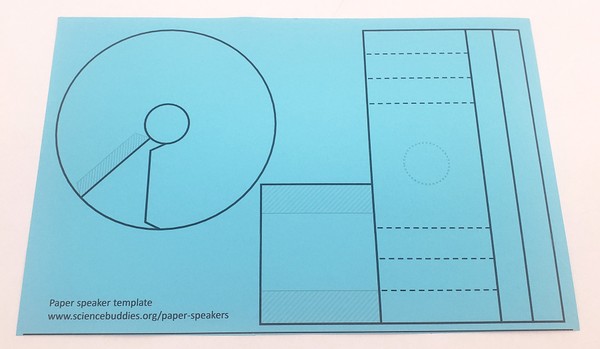
Figure 2. Paper speaker template. - Cut all the pieces of the template out along the solid lines (Figure 3).
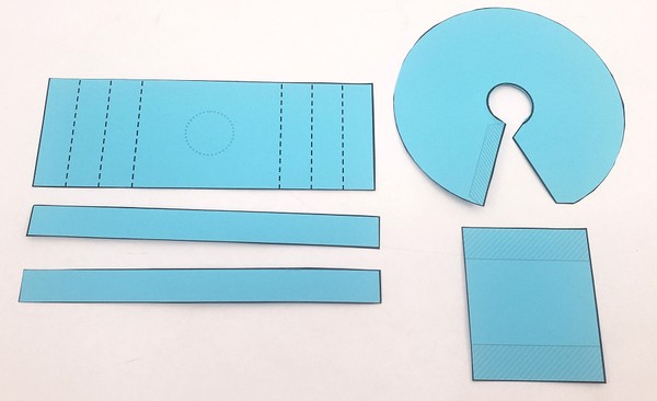
Figure 3. Template pieces cut out. - Wrap one of the long, narrow strips of paper tightly around the magnet (Figure 4).
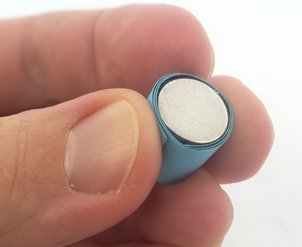
Figure 4. First strip of paper wrapped tightly around the magnet. - As you hold the paper-wrapped magnet firmly in place, begin wrapping the second long, narrow strip of paper around the first strip. Now use a dab of glue to hold the outer strip of paper in place so it does not unwind when you let go (Figure 5).
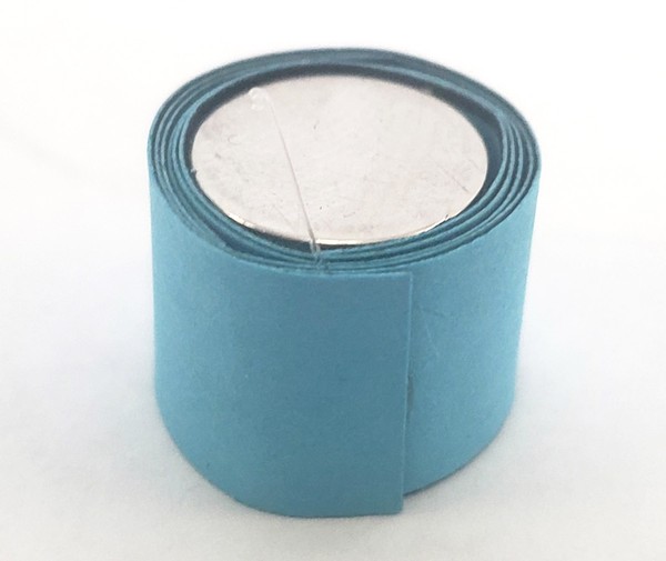
Figure 5. Both strips of paper wrapped around the magnet, with the outer strip glued in place. - Pull about 1 foot (30 cm) of wire from the spool of magnet wire (Figure 6). This extra length of wire will be used later to connect to the speaker.
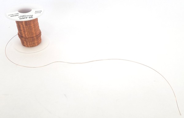
Figure 6. Spool of wire with about one foot of wire pulled out. - Working away from this extra length of wire, carefully, and tightly wrap 50 turns of wire from the spool around the paper tube to create a coil (Figure 7). The measured foot of wire should be left free at the beginning of the coil.
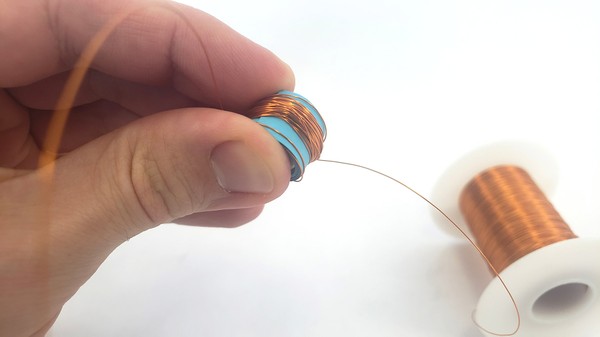
Figure 7. Coil created by wrapping wire tightly around the paper tube. - Measure out another foot of wire to leave free at the end of the coil and cut the wire (Figure 8).
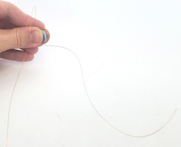
Figure 8. Completed wire coil with about one foot of free wire on each end. - Twist the two loose wires together and secure the coil with a few dabs of glue so it does not come unwound (Figure 9).
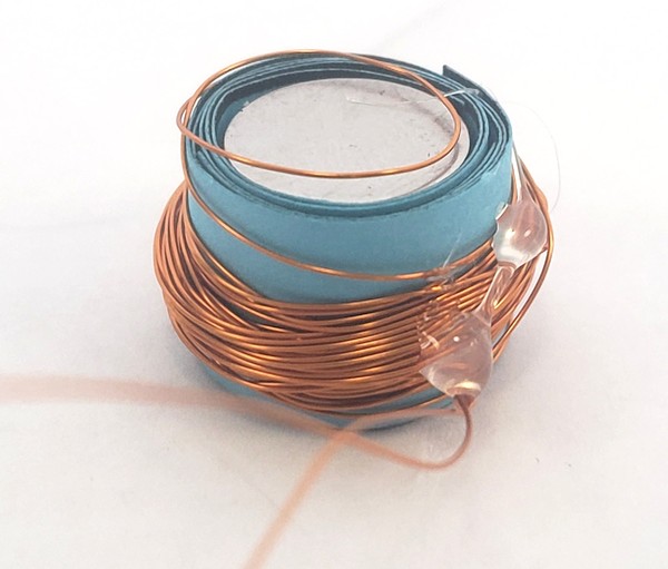
Figure 9. Completed coil secured with drops of glue. - After the glue has dried, push the magnet and the inner tube of paper out of the coil (Figure 10).
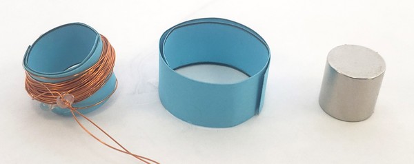
Figure 10. Inner paper tube and magnet removed from the paper tube with the wire coil. - Fold the large rectangular piece from the template along the dashed lines. Begin by folding the edges of the paper inwards and continue back and forth to form an accordion shape (Figure 11).
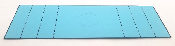
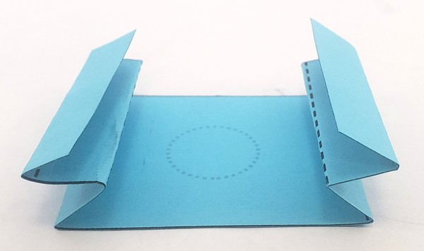
Figure 11. Top: rectangular template piece before folding. Bottom: piece after folding into accordion shape. - Glue the coil to the dashed circle on the accordion piece (Figure 12). Allow the glue to dry.
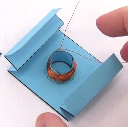
Figure 12. Coil glued to center of accordion piece. - Flip the accordion piece upside down. Using the small rectangle from the template as a base, glue the two accordion legs to the shaded areas of the rectangle (Figure 13). This completed piece will be the main body of the speaker.
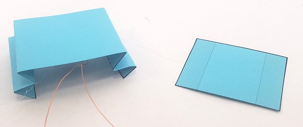
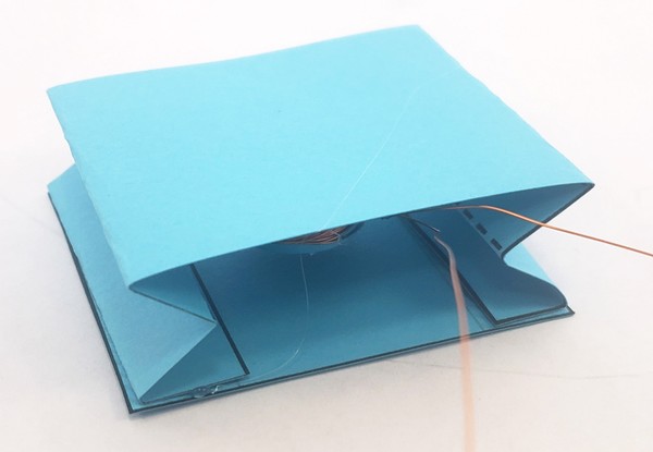
Figure 13. Top: accordion piece next to smaller rectangle base piece. Bottom: accordion piece glued to base piece. - Bend the cone slightly to glue the angled tab onto the shaded area (Figure 14). Allow the glue to dry.
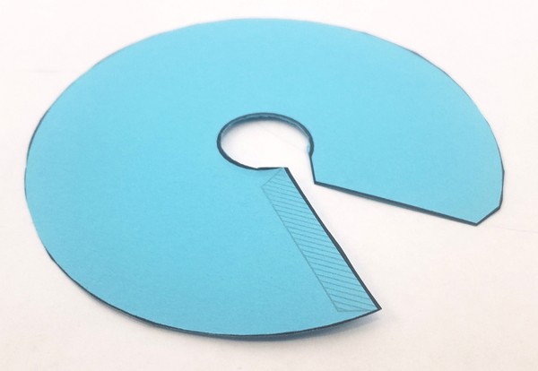
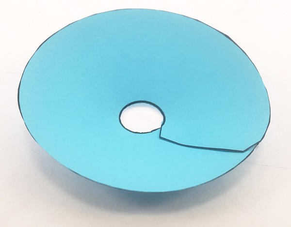
Figure 14. Top: speaker cone piece flat, before gluing. Bottom: piece with ends glued together, forming a cone shape. - Glue the bottom, smaller opening of the cone to the top of the speaker (Figure 15).
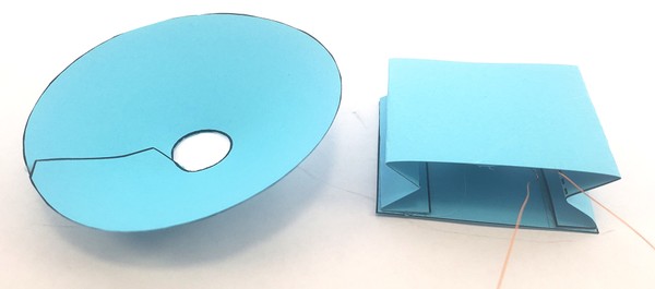
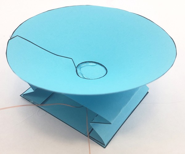
Figure 15. Top: speaker cone and speaker body. Bottom: speaker cone glued to top of speaker body. - Use sandpaper to strip the insulation from about 1 cm of each end of the wire. Fold the sandpaper in half, pinch the wire between the sides of the sandpaper with your fingers, and pull along the wire (Figure 16).
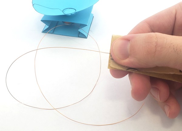
Figure 16. Magnet wire being stripped with a piece of sandpaper. - Repeat this multiple times while you rotate the wire. It can be difficult to tell when the insulation is removed, but if you look very closely, you should see that the underlying wire is a different color than the insulation (Figure 17).
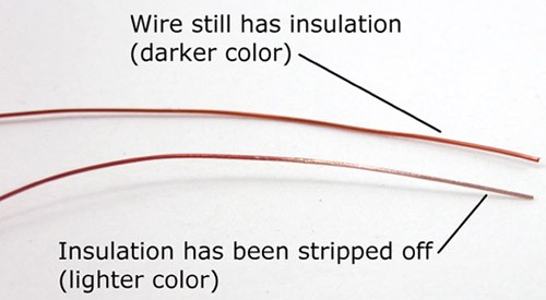
Figure 17. Close-up view of two pieces of wire, showing the difference in color once insulation has been removed. - One at a time, press down on a spring clip and insert one end of the magnet wire into the clip. Repeat for the other wire so they are next to each other (Figure 18).
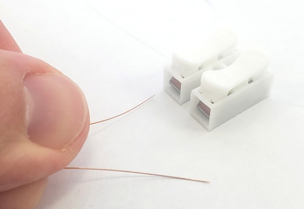
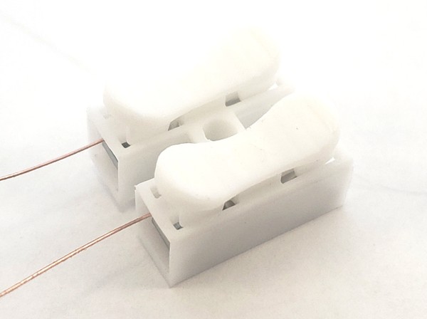
Figure 18. Top: wires before inserting into spring clips. Bottom: wires after inserting into spring clips. - Connect the loose wire ends of the audio cable to the other ends of the spring clips. There are three wires inside the audio cable: black (ground), red (left audio channel), and white (right audio channel). You need to connect the ground wire and one of the audio channels. Select the black wire and either the red or white wires, and connect them to the spring clips (Figure 19).
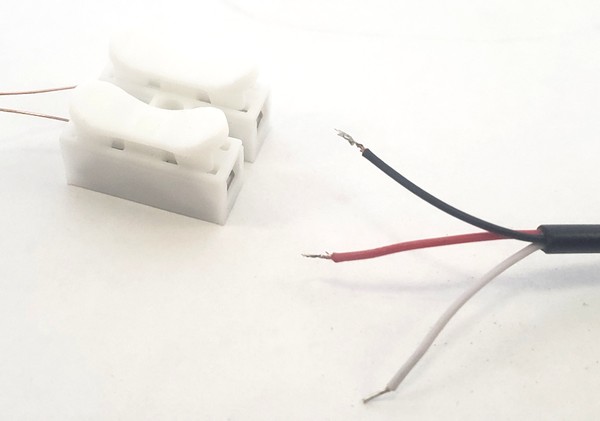
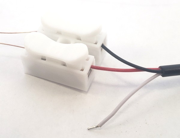
Figure 19. Top: audio wires before inserting into spring clips. Bottom: red and black wires inserted into spring clips, white wire left dangling. - Gently pull the top and bottom parts of the speaker apart, far enough that you can slide the magnet inside the coil, then let go and put the speaker down. The coil should sit over the magnet with the magnet resting on the base of the speaker (Figure 20). You do not need to glue the magnet in place—it is heavy enough that it will be held in place by its own weight. This allows you to easily remove it if you decide to test another speaker.
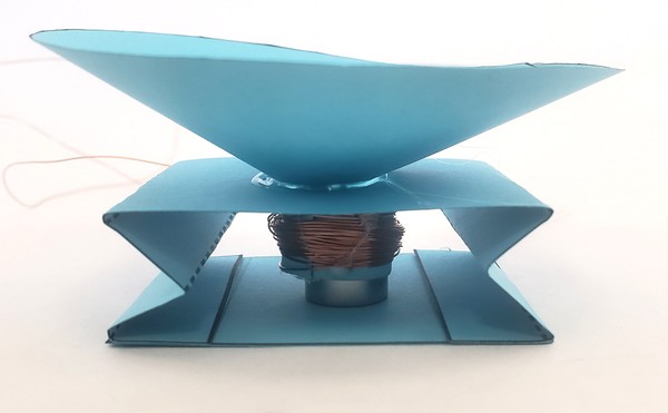
Figure 20. Magnet inserted into wire coil. - Plug the 3.5 mm cable into the headphone jack of your phone, tablet, or computer (Figure 21).
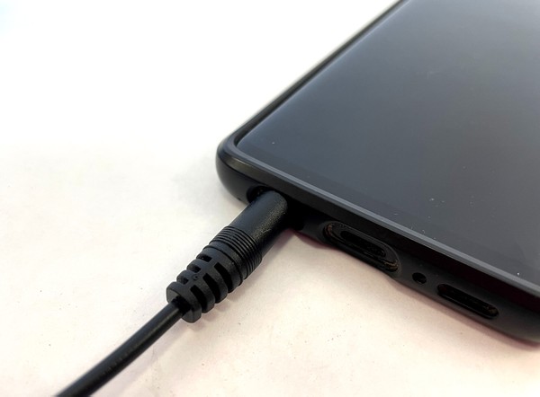
Figure 21. Audio cable plugged into headphone jack on a phone. - Make sure the volume on your device is all the way up, and try playing some music (Figure 22)!
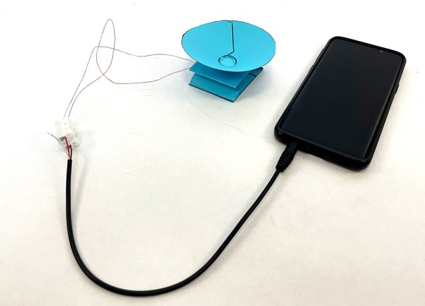
Figure 22. Completed project setup with speaker ready to play music. Can you hear music coming from your speaker? How loud is it compared to a "regular" speaker?
 - If you do not hear any music, try these troubleshooting steps and follow along with the video:
- Make sure you have the correct sound source selected on your phone or computer. For example, make sure you are not connected to a Bluetooth headset or speakers.
- Check that the volume on your device is turned all the way up.
- Check that the 3.5 mm cable is firmly plugged into the headphone jack.
- Make sure the spring clips are gripping the exposed metal parts of the 3.5 mm cable, not the insulated parts.
- Make sure you fully stripped the insulation off of the ends of the magnet wire.
- Make sure the exposed parts of the two magnet wires are not touching each other. This will create a short circuit.
- Make sure the magnet is not rubbing against the inside of the paper tube, as this will add friction and decrease the speaker's vibrations.
- Align the wire coil so it is around the top of the magnet. Magnetic fields quickly get much weaker with distance. If the coil and the magnet are too far away from each other, your speaker will not work.
/-/https/www.sciencebuddies.org/cdn/Files/18212/7/paper-speaker-assembly-1.jpg)
/-/https/www.sciencebuddies.org/cdn/Files/18213/7/paper-speaker-assembly-2.jpg)
/-/https/www.sciencebuddies.org/cdn/Files/18214/7/paper-speaker-assembly-3.jpg)
/-/https/www.sciencebuddies.org/cdn/Files/18232/7/paper-speaker-assembly-4.jpg)
/-/https/www.sciencebuddies.org/cdn/Files/18233/7/paper-speaker-assembly-5.jpg)
/-/https/www.sciencebuddies.org/cdn/Files/18234/7/paper-speaker-assembly-6.jpg)
/-/https/www.sciencebuddies.org/cdn/Files/18235/7/paper-speaker-assembly-7.jpg)
/-/https/www.sciencebuddies.org/cdn/Files/18236/7/paper-speaker-assembly-8.jpg)
/-/https/www.sciencebuddies.org/cdn/Files/18237/7/paper-speaker-assembly-9.jpg)
/-/https/www.sciencebuddies.org/cdn/Files/18215/7/paper-speaker-assembly-10.jpg)
/-/https/www.sciencebuddies.org/cdn/Files/18216/7/paper-speaker-assembly-11.jpg)
/-/https/www.sciencebuddies.org/cdn/Files/18217/7/paper-speaker-assembly-11a.jpg)
/-/https/www.sciencebuddies.org/cdn/Files/18218/7/paper-speaker-assembly-12.jpg)
/-/https/www.sciencebuddies.org/cdn/Files/18219/7/paper-speaker-assembly-13.jpg)
/-/https/www.sciencebuddies.org/cdn/Files/18220/7/paper-speaker-assembly-14.jpg)
/-/https/www.sciencebuddies.org/cdn/Files/18221/7/paper-speaker-assembly-15.jpg)
/-/https/www.sciencebuddies.org/cdn/Files/18222/7/paper-speaker-assembly-16.jpg)
/-/https/www.sciencebuddies.org/cdn/Files/18223/7/paper-speaker-assembly-17.jpg)
/-/https/www.sciencebuddies.org/cdn/Files/18224/7/paper-speaker-assembly-18.jpg)
/-/https/www.sciencebuddies.org/cdn/Files/7464/7/stripped-magnet-wire.jpg)
/-/https/www.sciencebuddies.org/cdn/Files/18225/7/paper-speaker-assembly-19.jpg)
/-/https/www.sciencebuddies.org/cdn/Files/18226/7/paper-speaker-assembly-20.jpg)
/-/https/www.sciencebuddies.org/cdn/Files/18227/7/paper-speaker-assembly-21.jpg)
/-/https/www.sciencebuddies.org/cdn/Files/18228/7/paper-speaker-assembly-22.jpg)
/-/https/www.sciencebuddies.org/cdn/Files/18229/7/paper-speaker-assembly-23.jpg)
/-/https/www.sciencebuddies.org/cdn/Files/18230/7/paper-speaker-assembly-24.jpg)
/-/https/www.sciencebuddies.org/cdn/Files/18231/7/paper-speaker-assembly-25.jpg)
/-/https/i.ytimg.com/vi/UupWNWZPR_Y/maxresdefault.jpg)
Test Your Speaker
- Set up your experiment in a quiet room where there are no other sources of noise.
- To measure your speaker's frequency response, you will play pure tones at different frequencies and measure the loudness of the speaker at that frequency. Make a data table like Table 1. At minimum, we recommend testing frequencies from 100–1,000 Hz in intervals of 100 Hz, and frequencies from 1,000–15,000 Hz in intervals of 1,000 Hz; however you can test more.
Table 1. Example data table.Loudness (dB) Frequency Trial 1 Trial 2 Trial 3 Average - Search for a tone generator app or website on the device you have connected to your speaker. The tone generator lets you play a pure tone (sine wave) at a specified frequency. Test the app/website with your speaker, for example with a 1,000 Hz tone, and make sure you can hear it. If it hurts your ears, turn the volume on your device down to a comfortable level. Make sure you keep the device volume constant for your entire experiment.
- Place your measurement device (decibel meter or phone) a fixed distance from your paper speaker. It is important to keep this distance and the orientation of the device constant throughout your experiment, as these can affect your measurements. Figure 23 shows an example experimental setup, with a laptop connected to the paper speaker and a decibel meter used to measure the sound.
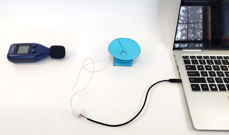
Figure 23. Experimental setup for testing your paper speaker's frequency response. - If you are using a decibel meter, read the instructions that came with your meter. If you are using the Phyphox® app, note that you will need to calibrate the audio amplitude sensor. The following video shows how to calibrate the sensor. Make sure your sensor is still calibrated each time you start a new recording in Phyphox, and re-calibrate it if necessary.
- Sit perfectly still and take a background noise reading with your decibel meter or app. Note that 0 dB is the threshold of human hearing, so even a very quiet room will not measure 0 dB. A quiet library is typically around 30 dB. The reading may fluctuate slightly. This is OK—you can take an average reading over a period of a few seconds.
- Now, play a 100 Hz tone and observe the decibel level. Make sure you sit still when observing the reading. Any movement (pushing buttons, writing in your lab notebook, etc.) will generate noise and affect the reading. Again, if the reading fluctuates slightly, take an average reading over a period of a few seconds. Record this reading in your data table.
- Repeat step 7 two more times for a total of three trials at that frequency.
- Repeat steps 7–8 for each frequency in your data table.
/-/https/www.sciencebuddies.org/cdn/Files/18244/5/paper-speaker-experiment-setup.jpg)
/-/https/i.ytimg.com/vi/3cpZEVSC6Nw/maxresdefault.jpg)
Build and Test Your Second Speaker
- Repeat the steps in the Build Your Speaker section, but this time, select a different speaker cone from the speaker cone template.
- Carefully remove the magnet from your first speaker and insert it into your second speaker.
- Repeat the steps in the Test Your Speaker section to test your second speaker. Record your data in a new data table.
Analyze Your Results
- For each speaker, calculate an average decibel level for each frequency that you measured.
- Plot the frequency response of each speaker (decibel level vs. frequency) on a single graph so you can compare them. Optionally, you can make your graph with a logarithmic scale on the x-axis. Logarithmic scales are frequently used when plotting frequency responses, because they do a better job of showing a large range of frequencies.
- The resonant frequency is the peak, or highest point on a frequency response. Can you find the resonant frequency for each speaker?
- How do the frequency responses and resonant frequencies of your two speakers compare? Does this match what you expect based on their size?
Ask an Expert
Variations
- Test additional speaker cone sizes. Can you collect enough data to predict a speaker's resonant frequency based on the diameter of the cone?
- Try playing different types of music with your speakers. Is there any audible difference between the two speakers?
- Try designing and building your own speakers with different materials, for example plastic cups or paper plates for the speaker cone. How does their sound and frequency response to compare to the speakers made from cardstock?
- Try measuring the frequency response of a real speaker.
Careers
If you like this project, you might enjoy exploring these related careers:
/-/https/careerdiscovery.sciencebuddies.org/cdn/Files/1223/17/iStock-971549326.jpg)
/-/https/careerdiscovery.sciencebuddies.org/cdn/Files/1801/18/pexels-photo-4988130.jpg)
/-/https/careerdiscovery.sciencebuddies.org/cdn/Files/916/17/unsplash-KGyzk-EvTwQ.jpg)
/-/https/careerdiscovery.sciencebuddies.org/cdn/Files/1233/17/unsplash-b28ac533a45f.jpg)
Contact Us
Our kits are developed in partnership with Home Science Tools®. If you have purchased a kit for this project, Home Science Tools® is pleased to answer any questions.In your email, please follow these instructions:
- Include your Home Science Tools® order number.
- Please describe how you need help as thoroughly as possible:
Examples
Good Question I'm trying to do Experimental Procedure step #5, "Scrape the insulation from the wire. . ." How do I know when I've scraped enough?
Good Question I'm at Experimental Procedure step #7, "Move the magnet back and forth . . ." and the LED is not lighting up.
Bad Question I don't understand the instructions. Help!
Good Question I am purchasing my materials. Can I substitute a 1N34 diode for the 1N25 diode called for in the material list?
Bad Question Can I use a different part?
Contact Support

/-/https/img.youtube.com/vi/5ZjbIC0c7KM/0.jpg)
/-/https/img.youtube.com/vi/bcfzUOdM8lg/0.jpg)
/-/https/img.youtube.com/vi/STl3JCwdOIY/0.jpg)