Abstract
How do self-driving cars stay on the road? How do vehicles with autonomous or driver-assist features automatically brake, steer around obstacles, or perform tasks like adaptive cruise control? Experiment with these behaviors and more in this science project as you build and program your own autonomous Arduino robot.
Summary
Previous experience with circuits and Arduino is recommended.
Bluebot 4-in-1 robotics kit and Science Buddies Electronics Kit for Arduino available from our partner Home Science Tools®. See the Materials section for details.
No issues
Valuable input provided by Analog Devices employees.
/-/https/i.ytimg.com/vi/qUo6hXSV1b8/maxresdefault.jpg)
Objective
Build a self-driving Arduino robot that can safely navigate a model roadway.
Introduction
Autonomous, self-driving, or driverless cars have the potential to reduce traffic fatalities and traffic congestion worldwide. A fully autonomous car would be capable of driving in all situations, without any input from a human driver. While cars have not yet achieved this level of autonomy, many new cars have a variety of driver-assist and safety features, such as automatic braking, lane departure warnings, and adaptive cruise control. Some have more autonomy and are able to self-drive in specific situations, such as on highways with well-marked lanes. Tesla is an example of a car company known for making cars with some autonomous driving features (Figure 1).
/-/https/www.sciencebuddies.org/cdn/Files/18249/19/tesla-car.jpg)
Figure 1. A Tesla, a type of car with some autonomous driving features.
Just as humans use our senses (sight, sound, touch, etc.) to perceive the world around us when driving, autonomous cars use a variety of electronic sensors to monitor the roadway and surroundings. Cameras work with complex computer vision systems to process visual information, while radar or ultrasonic sensors measure the distance between the car and other objects.
Based on information from these sensors, the car decides how to react—without input from the driver. For example, if a sensor detects that the car in front of it is rapidly slowing down, the car may automatically apply the brakes in order to slow down and avoid a collision. Or if the sensors detect that the car is driving out of its lane and off the side of the road, the car may automatically correct its steering to stay in the lane.
In this project you will build and program your own driverless vehicle using an Arduino, a popular microcontroller board used by many hobbyists and roboticists. You will connect sensors to the Arduino and program the vehicle to react to their input.
This is an advanced project, and prior experience with an Arduino is recommended. If you need help getting started, check out the references in the Bibliography.
Since autonomous vehicles are a rapidly evolving technology, you may want to do your own background research about recent developments and the current state of the art for driverless cars.
/-/https/i.ytimg.com/vi/YU17L650k3s/maxresdefault.jpg)
/-/https/i.ytimg.com/vi/n-gJ00GTsNg/maxresdefault.jpg)
Terms and Concepts
- Autonomous vehicle
- Self-driving car
- Driverless car
- Automatic braking
- Lane departure warning
- Adaptive cruise control
- Sensor
Questions
- What types of sensors do autonomous vehicles use?
- How do autonomous cars stay on the road?
- How do driverless cars avoid obstacles?
- Are self-driving cars better at driving than humans?
- How can you program your own autonomous Arduino vehicle?
Bibliography
General electronics references:
- Science Buddies (n.d.). How to Use a Breadboard. Retrieved July 6, 2020.
- Science Buddies (n.d.). How to Use a Multimeter. Retrieved July 6, 2020.
- Science Buddies (n.d.). Wire Stripping Tutorial. Retrieved July 6, 2020.
References for using an Arduino:
- Science Buddies (n.d.). How to Use an Arduino. Retrieved July 6, 2020.
- Arduino (n.d.). Language Reference. Retrieved July 6, 2020.
Datasheet for the L293D H-bridge motor driver:
- Texas Instruments (January 2016). L293x Quadruple Half-H Drivers. Retrieved July 8, 2020.
Datasheet for the IR sensor:
- Everlight Electronics Co., Ltd. (2007, April 4). Technical Data Sheet Opto Interrupter. Retrieved October 2nd, 2019.
Datasheet for the ultrasonic distance sensor:
- ElecFreaks (n.d.). Ultrasonic Ranging Module HC-SR04. Retrieved October 23, 2023.
Materials and Equipment 
Recommended Project Supplies
/-/https/www.sciencebuddies.org/cdn/Files/9118/11/bluebot-motion-activated-googly-1100_1.png)
Supplies to build your robot:
- BlueBot: 4-in-1 Robotics Kit, available from our partner Home Science Tools®. The kit includes a robot chassis, a breadboard, wheels, motors, batteries, and circuit parts to build four different robots.
-
Electronics Kit for Arduino, available from our partner Home Science Tools®.
- Note: This project will work with the Arduino UNO R3, UNO R4 Minima, UNO R4 WiFi, and compatible third-party boards.
- Windows or Mac computer. See this page if you have a Chromebook. Your computer will need:
- Access to the Arduino IDE, either installed local version or web-based editor. Watch this video for a comparison of the two options.
- USB port. The Science Buddies kit comes with a USB-A to C cable. The "C" end plugs into the Arduino, and the "A" end plugs into your computer. You will need an adapter or different cable if your computer only has USB-C ports. Watch this video to learn about the different types of cables and adapters.
- Additional recommended tools for working with circuits:
- A digital multimeter for help with troubleshooting (strongly recommended)
- Alligator clip leads to easily connect multimeter probes to the circuit
- Needle nose pliers or tweezers make it easier to handle small parts
- Wire strippers to cut wires to custom lengths, keeping your circuit neater
- Double-sided foam tape
- Craft sticks
Materials to build a road for your robot, such as:
- Posterboard for the ground
- Black construction paper or cardstock for the road
- Clear tape to attach the paper to the posterboard
- White and yellow electrical tape for roadway lines
- Assorted toys or other small objects to use as obstacles
Disclaimer: Science Buddies participates in affiliate programs with Home Science Tools®, Amazon.com, Carolina Biological, and Jameco Electronics. Proceeds from the affiliate programs help support Science Buddies, a 501(c)(3) public charity, and keep our resources free for everyone. Our top priority is student learning. If you have any comments (positive or negative) related to purchases you've made for science projects from recommendations on our site, please let us know. Write to us at [email protected].
Experimental Procedure
- Build an arena or road for your self-driving car.
The one shown in Figure 2 is just a suggestion. You can use other materials and other shapes for the road, including different combinations of curves, intersections, etc. In general, you should make sure your road has at least one lane that is wide enough for your robot and is clearly marked by lane lines on both sides. Make sure the lines are much lighter than the road surface (e.g., white and yellow tape on a black road).
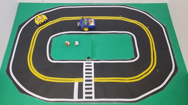 Figure 2. An example road to test your self-driving car, made from posterboard, cardstock, and tape.
 - Assemble your Bluebot chassis.
Follow the instructions in this video; however, instead of mounting the 4xAA battery pack on top of the robot, mount it on the lower plate. Then mount your Arduino next to the breadboard on the top plate. This will give you easier access to the circuit when connecting it to the Arduino.
- Assemble your circuit.
If you plan to use the example code provided by Science Buddies, assemble the circuit as shown in Figures 3 and 4. The Arduino pins used in this diagram match the ones used in our example code (see Step 4). If you try to use our example code without matching this wiring diagram exactly, the code will not work properly.
Important: the left/right orientation of the power and ground buses on your breadboard may be reversed from what is shown in Figure 3. Make your connections to the power and ground buses as described, do not just rely on the absolute left/right positions in Figure 3.
Take your time and carefully double-check all of your wiring. This is a complicated circuit with a lot of connections. You should connect the batteries last to avoid the risk of creating short circuits while you work.
Note: It is important to make sure all components in the circuit have a common ground, but you must be very careful not to short different positive voltages together (e.g., 5 V from the Arduino and 6 V from the 4xAA battery pack).
Following is one suggested order in which you can build the circuit, but you do not need to do it in this order.
Note: Connections are made with male-male jumper wires unless otherwise indicated.
- Connect the left and right ground buses on the breadboard. Do not connect the two power buses. You will use them for different voltages.
- Connect the Arduino's GND pin to the breadboard's ground bus.
- Connect the Arduino's 5 V pin to the breadboard's right-side power bus.
- Pins on the L293D H-bridge are numbered 1–16, counterclockwise from the top left. Connect them as follows. Important: locate the semi-circular notch in one end of your H-bridge chip. That notch should face "up" toward the top of the breadboard (row 1). If you put your H-bridge in upside-down, your circuit will not work properly.
- Pin 1 to Arduino pin 10
- Pin 2 to Arduino pin 3
- Pin 3 to the right motor's negative wire
- Pin 4 to ground
- Pin 5 to ground
- Pin 6 to the right motor's positive wire
- Pin 7 to Arduino pin 2
- Pin 8 to the left-side power bus (which will be connected to 6V later)
- Pin 9 to Arduino pin 9
- Pin 10 to Arduino pin 4
- Pin 11 to the left motor's positive wire
- Pin 12 to ground
- Pin 13 to ground
- Pin 14 to left motor's negative wire
- Pin 15 to Arduino pin 5
- Pin 16 to 5 V
- Connect the ultrasonic sensor using male-female jumper wires.
- GND pin to ground
- 5V V pin to 5 V
- Trig pin to Arduino pin 11
- Echo pin to Arduino pin 7
- Looking at the bottom (with the pins facing you), orient the infrared (IR) sensor so the small notch in one corner is to the lower right (see Figure 5 for recommended color coding). Connect the left sensor as follows:
- Pin 1 to 5 V through a 220 Ω resistor
- Pin 2 to ground
- Pin 3 to ground
- Pin 4 to 5 V through a 10 kΩ resistor and to Arduino analog input pin A0
- Connect the right IR sensor as follows:
- Pin 1 to 5 V through a 220 Ω resistor
- Pin 2 to ground
- Pin 3 to ground
- Pin 4 to 5 V through a 10 Ω resistor and to Arduino analog input pin A1
- Connect an LED with a 220 Ω current-limiting resistor between Arduino pin 8 and ground.
- Connect an LED with a 220 Ω current-limiting resistor between Arduino pin 6 and ground.
- Finally, connect the 4xAA battery pack to your circuit.
- Connect the negative wire to the breadboard's ground bus.
- Instead of connecting the positive wire directly to the left-side power, connect it to a switch on the breadboard first, then connect the switch to the left-side power bus (assuming you previously connected the right-side power bus to 5 V; remember not to short the two voltages together). This will allow you to easily turn the battery pack on and off.
 Figure 3. A breadboard view of the circuit.
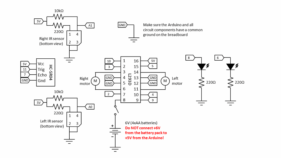 Figure 4. A schematic view of the circuit.
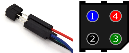 Figure 5. Male-female jumper wires connected to the IR sensor's pins. You will see a small diagonal notch on one corner of the sensor. With the pins facing you and this notch in the lower right, the pins are numbered 1, 2, 3, 4 counter-clockwise starting from the upper left. Connect blue, black, green, and red wires to pins 1, 2, 3 and 4 respectively.
 - Mount the infrared and ultrasonic sensors on your robot using craft sticks and tape.
The ultrasonic sensor should be on the front of the robot, facing forward, at an appropriate height to detect obstacles.
The infrared sensors should be on the left and right of the robot, toward the front, facing downward, a few millimeters from the ground. See Figure 6.
 Figure 6. Sensors mounted to the front of the robot with tape and craft sticks.
 - Download and review the starter code for your autonomous vehicle.
Carefully read through the commented code. This code has commands to control the robot's motors and to take readings from the sensors, but it does not have an algorithm to tell the robot how to drive based on the sensor readings. Coming up with that part is your job!
- Calibrate your sensors.
The infrared sensors can be affected by ambient light conditions in the room and their distance from the ground, so they must be calibrated before use.
- Make sure the switch for your 4xAA battery pack is off.
- Upload the starter code to your Arduino and leave the Arduino plugged into the USB cable.
- Open the serial monitor (Tools → Serial Monitor).
- Wave your hand back and forth in front of the ultrasonic sensor. The "ultrasonic sensor (cm)" value should change.
- Place your robot on the road and move it around so one of the sensors goes over one of the lines you made with tape. The reading for that IR sensor should change. Compare the reading to the value when the sensor is over the dark road. Experiment with the sensors to determine a good "threshold" value (i.e., when the reading is below that value, you know the sensor detects a line). You can set the thresholds for the left and right sensors separately in the code using the leftIRthreshold and rightIRthreshold variables. The thresholds might be different, especially if the sensors are not the same distance from the ground.
- Develop an algorithm for your robot.
You can sketch this algorithm using a flowchart (Figure 7) or "pseudocode" (Figure 8)—conceptual code where you do not worry about the exact syntax or use of proper commands. Figures 7 and 8 show example code for a robot that drives in a clockwise loop (i.e., makes a continuous right turn) without driving off the left edge of the road. (This very simple code would not work for making a left turn or other more complex behaviors like stopping at intersections or avoiding obstacles.)
Here are some ideas for other things you can try:
- Make your robot automatically stay in a lane (avoid driving over the line on either the left or right side).
- Make the robot automatically stop at a crosswalk (when both sensors detect a line).
- Make the robot automatically stop if there is an obstacle less than a certain distance in front of it.
- Make the robot stop at an intersection, make a 90 degree turn, and then keep driving.
- Make the robot back up and turn around when it encounters an obstacle that does not move out of the way after a certain amount of time.
- Advanced: implement "adaptive cruise control" by making the robot automatically try to stay a fixed distance behind an object in front of it.
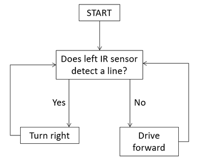
From the starting point, the chart asks 'Does the left IR sensor detect a line?' If yes, the vehicle should turn right. If no, it should drive forward. In either case, return to 'Does the left IR sensor detect a line?'
Figure 7. A very simple flowchart representing an algorithm for a robot to drive in a clockwise circle without crossing a line.
Start program
Loop:
Does the left IR sensor detect a line?
If yes, turn right
If not, drive forwardFigure 8. Pseudocode for the flowchart shown in Figure 7. - Test your algorithm.
Edit the starter code to implement your algorithm. When you are ready, upload the code to your Arduino and place the robot on your road. This time you will need to disconnect the USB cable and power your Arduino with the 9 V battery instead. When you are ready, turn on the power switch to the 4xAA battery so the motors can start spinning. Watch your robot go!
- Troubleshoot your robot's behavior.
Watch your robot closely and analyze its behavior. Does it match what you expect based on your algorithm? It might not work perfectly on the first try, and that is okay. Now it is time to debug!
Common issues and troubleshooting steps include, but are not limited to, the following:
- The robot fails to detect a line. Double-check your IR sensor readings and adjust the threshold variables if needed. Also try to make sure your road is as flat as possible, as the distance between the sensor and the ground will affect the reading.
- The robot detects the line, but overshoots turns. Try adjusting the turnspeed1 and turnspeed2 variables to change how fast the robot turns. You can also adjust the straightspeed variable to change how fast the robot drives straight.
- The robot does not drive straight when both motor speed variables are the same. This can happen if one motor has slightly more friction than the other. You can compensate for this by changing the motor speeds so they are not both the exact same value.
- Make changes to your code based on your observations and try again.
Keep iterating and improving your code until you get the performance you want out of your self-driving Arduino car.
/-/https/www.sciencebuddies.org/cdn/Files/18254/8/self-driving-car-paper-road.jpg)
/-/https/i.ytimg.com/vi/SBeGl_IgWwY/maxresdefault.jpg)
/-/https/www.sciencebuddies.org/cdn/bluebot-autonomous-car-HCSR04-breadboard-diagram.png)
/-/https/www.sciencebuddies.org/cdn/bluebot-autonomous-car-circuit-diagram.png)
/-/https/www.sciencebuddies.org/cdn/Files/6320/34/IR-sensor-jumpers-line-following-18.png)
/-/https/www.sciencebuddies.org/cdn/Files/18257/8/self-driving-arduino-car.jpg)
/-/https/www.sciencebuddies.org/cdn/Files/18258/8/robot-algorithm-flowchart.png)
Troubleshooting
For troubleshooting tips, please read our FAQ: Build a Miniature Self-Driving Car.
Ask an Expert
Global Goals
The United Nations Sustainable Development Goals (UNSDGs) are a blueprint to achieve a better and more sustainable future for all.
/-/https/www.sciencebuddies.org/cdn/Files/19752/5/E-WEB-Goal-09.png)
Variations
- Add features to your car using other sensors in your Bluebot kit, like the bump sensors or the light sensors. See this bump sensor project and this light sensor project for ideas. Important: be careful with how you connect the bump sensor to your Arduino. The red wire is for the "common" pin, the white wire is for the "normally open" pin, and the black wire is for the "normally closed" pin. Even though red and black are typically used for power and ground, do not connect the red wire to +5V and the black wire to ground - this will create a short circuit. Instead, you can make the following connections, which will allow you to use the bump sensor the same way you would use a slide switch.
- White wire to +5V
- Black wire to ground
- Red wire to Arduino input pin
- You can use your IR sensors to prevent your robot from driving off a cliff! See this Arduino project for ideas.
- Purchase an Arduino-compatible color sensor and use it to detect traffic lights or traffic signs on your model roadway.
Frequently Asked Questions (FAQ)
Careers
If you like this project, you might enjoy exploring these related careers:
/-/https/careerdiscovery.sciencebuddies.org/cdn/Files/928/17/ThomasWallner.jpg)
/-/https/careerdiscovery.sciencebuddies.org/cdn/Files/1725/18/4161_Michelle_Easter_and_Curiousity_Clone.jpg)
/-/https/careerdiscovery.sciencebuddies.org/cdn/Files/1223/17/iStock-971549326.jpg)
/-/https/careerdiscovery.sciencebuddies.org/cdn/Files/1163/18/pexels-photo-1181472.jpg)
Contact Us
Our kits are developed in partnership with Home Science Tools®. If you have purchased a kit for this project, Home Science Tools® is pleased to answer any questions not addressed by the FAQ above.In your email, please follow these instructions:
- Include your Home Science Tools® order number.
- Please describe how you need help as thoroughly as possible:
Examples
Good Question I'm trying to do Experimental Procedure step #5, "Scrape the insulation from the wire. . ." How do I know when I've scraped enough?
Good Question I'm at Experimental Procedure step #7, "Move the magnet back and forth . . ." and the LED is not lighting up.
Bad Question I don't understand the instructions. Help!
Good Question I am purchasing my materials. Can I substitute a 1N34 diode for the 1N25 diode called for in the material list?
Bad Question Can I use a different part?
Contact Support

/-/https/img.youtube.com/vi/s7bopU_N_fQ/0.jpg)
/-/https/img.youtube.com/vi/BTiCgA8cufA/0.jpg)
/-/https/img.youtube.com/vi/SYJP36RJKPA/0.jpg)