The Point of a Parabola: Focusing Signals for a Better Wireless Network
Abstract
Have you ever been annoyed by poor Wi-Fi reception for your phone, tablet, or laptop? Do you wish there was something you could do about it? In this project you will learn how to build a parabolic reflector that you can attach to the antenna of a regular wireless router to help boost its signal.Summary
This project was revised by Ben Finio, Ph.D., Science Buddies
Thank you to Amandip Sehmbey of Motorola Solutions, Inc. for providing technical insights during the revising of this project.
This project was originally written by Andrew Olsen, Ph.D., Science Buddies. The antenna in this project is based on the template provided by M. Erskine.
- Scotch is a registered trademark of 3M Company.
- Elmer's is a registered trademark of Elmer's Products, Inc.

Objective
Build a parabolic reflector and measure how it boosts the signal of your wireless router's antenna.
Introduction
Chances are that you have used a wireless device like a smartphone, tablet, or laptop to access a Wi-Fi network, either at home or in a public place like a library or school. Have you ever noticed that the signal strength of the Wi-Fi network can vary depending on where you are? The wireless connection is formed between your device and a wireless router. Your device and the router each have an antenna that can broadcast and receive a Wi-Fi signal. In general, if you get too far away from the router, or if there are certain materials (like metal or concrete) in between you and the router, the signal will get weaker.
How can you improve the strength of a wireless signal, for example, for a computer that has to be much farther away from the router than usual? One way to do this is by using a parabolic reflector. A parabola, shown in Figure 1, below, is a special mathematical shape — a curve consisting of the points that are equidistant from both a given fixed point called the focal point or (focus) and a given fixed line (called the directrix).
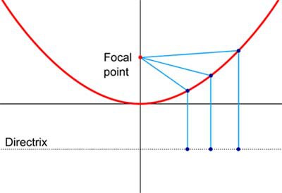 Image Credit: Wikimedia Commons user Perey, edited by Ben Finio, Science Buddies / Public Domain
Figure 1. Every point on a parabola (curved red line) is equidistant from both a given point called the focal point and a given line called the directrix. (original image credit Wikimedia Commons user Perey)
Something is truly special about a parabola's shape. Any rays that originate at the focal point will be reflected outward, parallel to the parabola's axis of symmetry. Any parallel rays that come into the parabola will be reflected inward to the focal point. This is illustrated in Figure 2, below.
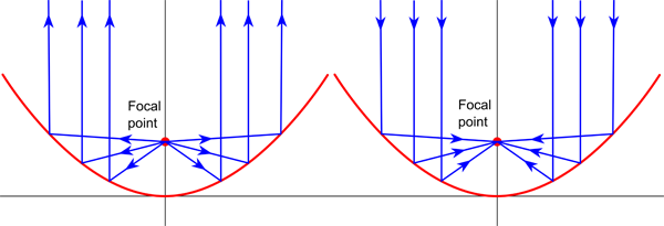 Image Credit: Wikimedia Commons user KaiMartin, edited by Ben Finio, Science Buddies / Public Domain
Figure 2. Left: Rays that originate at the focus of a parabola will be reflected outward, parallel to each other. Right: Incoming parallel rays will be reflected inward toward the focus. (original image credit Wikimedia Commons user KaiMartin)
The reflecting properties of a parabola make parabolic reflectors useful in many practical applications. For example, flashlights use parabolic reflectors to reflect light from the bulb forward in a concentrated beam, and some solar collectors use a parabolic reflector to concentrate the sun's rays to heat water or generate electricity (see Figure 3, below). Parabolic reflectors can also be used to help broadcast and receive Wi-Fi signals.
 Image Credit: Wikimedia Commons user kjkolb / Creative Commons Attribution-Share Alike 3.0 Unported
Figure 3. A parabolic reflector in a solar array helps concentrate the sun's energy to heat a liquid. The heated liquid is ultimately used to generate electrical power. (image credit Wikimedia Commons user kjkolb)
In this science project, you will build a parabolic reflector and attach it to the regular antenna of a wireless router. Then, you will measure how the direction in which the reflector is pointing affects the Wi-Fi signal strength at a certain location. Using the information on this page and the references below, do some background research on Wi-Fi signals, parabolas, and parabolic reflectors, and use this information to formulate your hypothesis.
Wireless signal strength is measured in units called decibel-milliwatts, or dBm. Decibel-milliwatts are different from the regular metric units you are probably used to working with like meters, grams, and seconds. Decibel-milliwatts measure the power level of a signal relative to a base level of 1 milliwatt (mW), which is equal to 0 dBm. So, positive dBm values have a power greater than 1 mW, and negative dBm values have a power less than 1 mW. The values you measure for this project will probably be negative. It is important to note that a value that is closer to zero means a stronger signal than a value that is farther away from zero. For example, a signal strength of -15 dBm is a fairly strong signal, whereas a signal strength of -90 dBm is a very weak signal. For more detailed information about dBm, see the reference in the Bibliography below.
Terms and Concepts
- Wi-Fi
- Signal strength
- Router
- Antenna
- Parabola
- Parabolic reflector
- Decibel-milliwatts (dBm)
Questions
- What are the important components of a wireless network?
- What is a parabola? What special reflective properties does a parabola have?
- What is a parabolic reflector? What practical uses do parabolic reflectors have?
- How will the direction in which a parabolic reflector is facing affect wireless signal strength?
- What will happen to wireless signal strength if the reflector is pointed directly toward your wireless device (smartphone, tablet, or laptop)?
- What will happen to wireless signal strength if the reflector is pointed directly away from your wireless device?
- What is a decibel-milliwatt? What is a stronger signal, one with a strength of -20 dBm or -80 dBm?
Bibliography
- Pierce, R. (2014, February 3). Parabola. Math Is Fun. Retrieved March 24, 2014.
- Brain, M., Wilson, T., and Johnson, B. (2001, April 30). How WiFi works Retrieved March 25, 2014.
- Erskine, M. (2003). Deep Dish Cylindrical Parabolic Template. Retrieved March 25, 2014.
- Wikipedia contributors. (2014, March 19). dBm. Wikipedia, The Free Encyclopedia. Retrieved March 25, 2014.
Materials and Equipment
Following is a list of suggested materials to build the parabolic reflector. Many other options exist for building the reflector using materials you can find around the house. For some other ideas, see the Gallery of Successful Builds section of the Deep Dish Cylindrical Parabolic Template website listed in the Bibliography.
- Piece of corrugated cardboard, at least 20 x 15 cm
- Piece of thin cardboard — for example, from a cereal box — at least 20 x 25 cm
- Enough aluminum foil to cover the thin piece of cardboard
- String (about 50 cm)
- Duct tape and/or Scotch® tape
- Metric ruler
- Scissors
- Pen or pencil
- Hobby knife or other sharp knife
- Elmer's® glue
- Protractor
- Posterboard or large piece of cardboard
- Volunteer to help build antenna and run the experiment
To test the reflector's ability to boost a wireless signal, you will need:
- Wireless router with an external antenna
- Some wireless routers have two external antennas. You will need to temporarily remove one of the antennas to do this project. Be sure to re-attach the antenna when you have finished the project.
- Some wireless routers only have internal antennas, which means you cannot easily put the antenna at the focal point of a parabolic reflector. If this is the case with your router, you can purchase a USB Wi-Fi antenna, available from Amazon.com, for a laptop or desktop computer. You will then have to adapt the procedure to use the parabolic reflector on your computer's antenna instead of the router.
- Smartphone, tablet, or laptop with Internet connection
- Program to analyze the strength of the wireless signal. You will need to find a program that works with your wireless device and operating system.
- For a Windows device, you can use WifiInfoView (Windows Vista, 7, and 8) or WirelessNetView (Windows XP). Note that these programs are designed to work with native Windows wireless drivers and not third-party drivers, so you may need to disable third-party drivers to get them to work. Ask an adult if you need help getting these programs to run.
- For an Android device, you can use Wifi Analyzer.
- For a Macintosh running OS X 10.9 or higher, you can use WiFi Strength Indicator.
- For other operating systems, you will have to search for an app or program that measures Wi-Fi signal strength in dBm. It may not be possible to do this project with iOS devices or older Mac OS X devices.
Disclaimer: Science Buddies participates in affiliate programs with Home Science Tools, Amazon.com, Carolina Biological, and Jameco Electronics. Proceeds from the affiliate programs help support Science Buddies, a 501(c)(3) public charity, and keep our resources free for everyone. Our top priority is student learning. If you have any comments (positive or negative) related to purchases you've made for science projects from recommendations on our site, please let us know. Write to us at scibuddy@sciencebuddies.org.
Experimental Procedure
Building Your Parabolic Reflector
- Download the parabolic reflector template, shown in Figure 4, below.
- Print the template on an 8.5 x 11 inch sheet of paper.
- Use a ruler to check that the sides of the calibration square in the corner of the sheet are of equal length. If the square appears skewed (one side is longer than the other), you will need to adjust the settings on your printer (for example, the page margins) and try again.
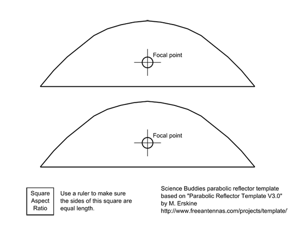 Image Credit: Ben Finio, Science Buddies / Science Buddies
Figure 4. The parabolic reflector template.
- Use scissors to cut out the outline of one of the parabolas, as shown in Figure 5, below. A second parabola is provided in the template in case you make a mistake with the first one.
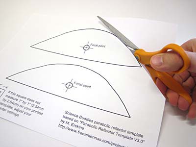 Image Credit: Ben Finio, Science Buddies / Science Buddies
Figure 5. Use scissors to cut out the parabola.
- Trace two copies of the parabola onto a piece of corrugated cardboard, as shown in Figure 6, below. Make sure you poke a hole in the cardboard for the focal point.
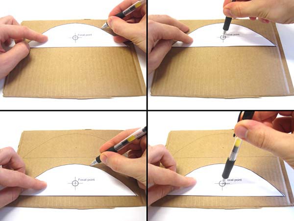 Image Credit: Ben Finio, Science Buddies / Science Buddies
Figure 6. Trace the parabola onto corrugated cardboard, using the tip of the pen to poke a hole in the cardboard for the focal point.
- Use scissors to carefully cut the parabolic shapes out of the corrugated cardboard, as shown in Figure 7, below.
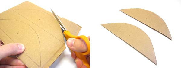 Image Credit: Ben Finio, Science Buddies / Science Buddies
Figure 7. Use scissors to cut the parabolas out of the cardboard.
- Use a pen or pencil to make a small "+" symbol (about 1 centimeter [cm] wide) centered on each focal point. Then, use a sharp knife to cut slits in the "+", as shown in Figure 8, below. This will make it easier to push your Wi-Fi router's antenna through the cardboard when you do your testing.
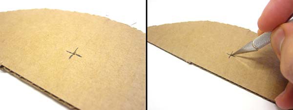 Image Credit: Ben Finio, Science Buddies / Science Buddies
Figure 8. Cut slits at the focal point so you can push the antenna through the cardboard.
- Use scissors to cut four small rectangles and four small triangles out of your scrap pieces of corrugated cardboard. The exact size of these pieces is not critical — they will be used as spacers to separate your two parabolas. Use Figure 9, below, to get a rough idea of the appropriate size.
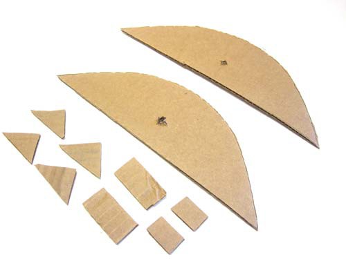 Image Credit: Ben Finio, Science Buddies / Science Buddies
Figure 9. Cut out small cardboard spacers in the shape of triangles and rectangles.
- Glue the two cardboard parabola pieces together, using the spacers as shown in Figure 10, below.
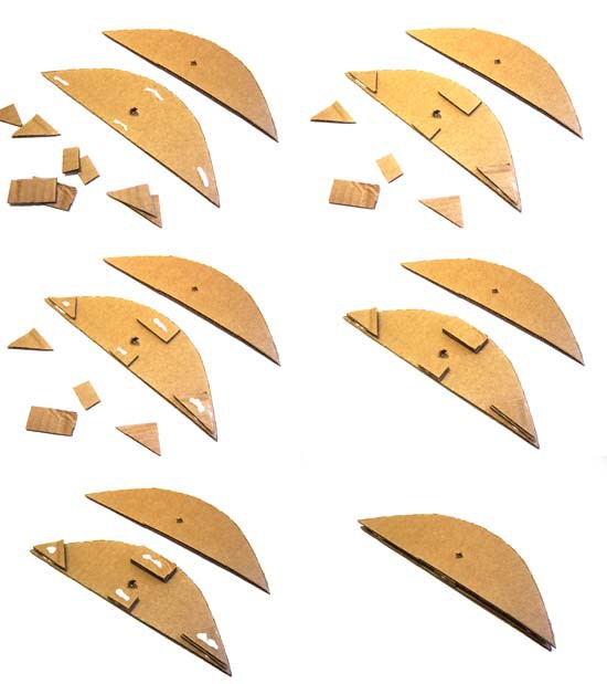 Image Credit: Ben Finio, Science Buddies / Science Buddies
Figure 10. Glue the two cardboard parabolas together, using the small spacers.
- Use scissors to cut out one side of a cereal box. Make sure the side is at least 20 x 25 cm (the Cheerios® box in Figure 11, below, is slightly larger, 29 x 24 cm). Cover one side of the cardboard completely in aluminum foil, and tape the edges of the aluminum foil to the back side of the cardboard cereal box, as shown in Figure 11.
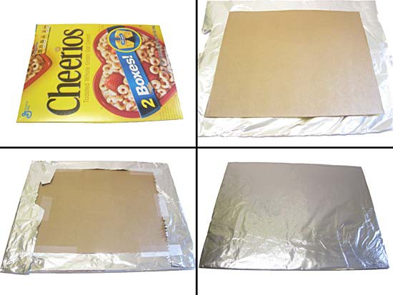 Image Credit: Ben Finio, Science Buddies / Science Buddies
Figure 11. Cover a thin sheet of cardboard in aluminum foil.
- Attach the aluminum foil-covered cardboard to your parabolic template, as shown in Figure 12, below.
- Use a sharp knife to punch small holes near the edges in opposite sides of the foil-covered cardboard (centered on the height of the cardboard, as shown in Figure 12), so you can thread a string through them.
- Have a volunteer hold the cardboard in place against the curved edge of the parabolic template, while you thread the string from hole to hole in the cardboard and tie it tightly in place so the cardboard holds its curved shape. Make sure you pull the string taut before tying it tightly in place, otherwise the cardboard will not properly hold its shape.
- Use tape to secure the foil-covered cardboard to the parabolic template. This will enable you to mount the entire structure on your router's antenna.
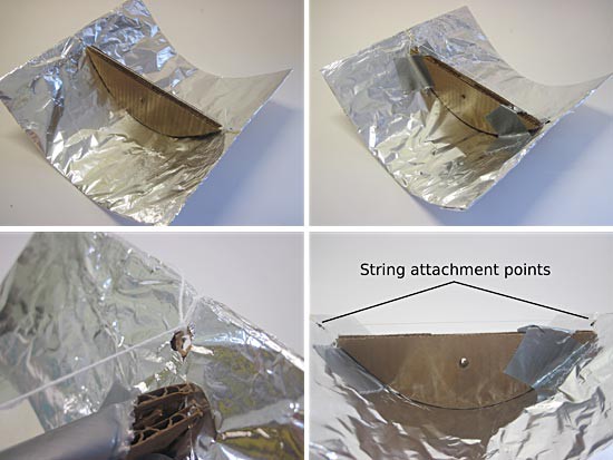 Image Credit: Ben Finio, Science Buddies / Science Buddies
Figure 12. Use string and tape to secure the foil-covered cardboard against the curved edge of the parabolic template. Top left: Even though the foil-covered cardboard has not been taped to the parabolic template yet, the string helps the cardboard hold its curved shape. Top right: Duct tape holds the foil-covered cardboard to the parabolic template, which will mount to the router's antenna. Bottom left: a close-up shot of string tied to a hole near the edge of the foil-covered cardboard. Bottom right: A side view showing the two locations where the string attaches to the foil-covered cardboard.
- Your completed parabolic reflector should be able to stand up on its own, as in Figure 13, below. If your reflector seems flimsy, try using additional tape or cardboard to strengthen it if necessary.
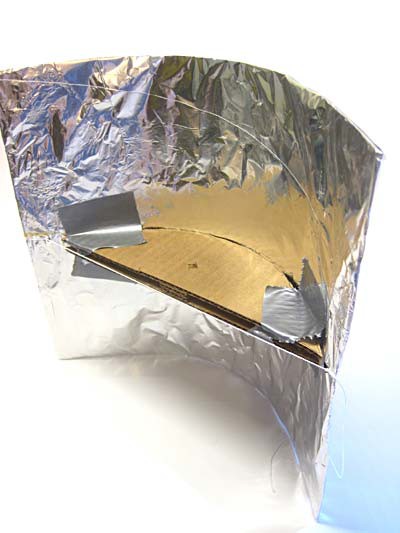 Image Credit: Ben Finio, Science Buddies / Science Buddies
Figure 13. A completed parabolic reflector.
Setting Up Your Wireless Router
- Check to see which type of antenna your router has. Some wireless routers, like the one in Figure 14, below, have two external antennas. Others may have only one external antenna, or they may have internal antennas. If you cannot see an antenna on the back or sides of your router, that means it has an internal antenna.
- If your router has an internal antenna, you will need to purchase a USB Wi-Fi antenna for use with a laptop or desktop computer (see the Materials list), and adapt the rest of the Procedure to attach the parabolic reflector to this antenna, instead of the router's antenna.
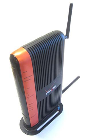 Image Credit: Ben Finio, Science Buddies / Science Buddies
Figure 14. A wireless router with two antennas.
- If your router has two antennas, unscrew one of them from the back of the router, as shown in Figure 15, below. You will have to decide which antenna will be best for mounting your parabolic reflector (in this case, the antenna towards the top of the router), and then remove the other antenna (in this case, the one at the bottom). Keep the antenna in a safe place so you do not lose it, and remember to reattach it at the end of your experiment. Ask an adult if you need help.
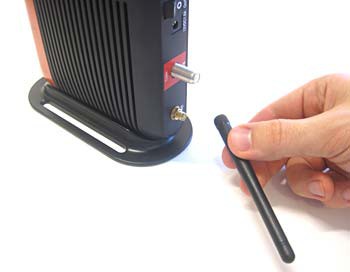 Image Credit: Ben Finio, Science Buddies / Science Buddies
Figure 15. Unscrew the second antenna, if there is one, from the back of the router.
- Carefully slide your router's antenna through the focal-point slots on your parabolic reflector, as shown in Figure 16, below. Be careful not to break your reflector — if it is too hard to push the antenna through, use a knife to make the slots slightly bigger.
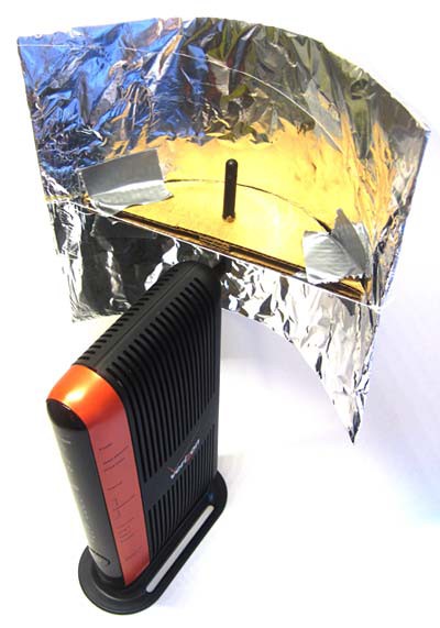
Figure 16. A completed parabolic reflector attached to the antenna of a Wi-Fi router. Note that the normal power and Internet cables have been disconnected from the router for this picture.
Build an Angle Template
- Use a protractor, marker, and posterboard or large piece of cardboard to make an angle template like the one shown in Figure 17, below. Make sure that the template is large enough that you can still read the degree markings when the router and parabolic reflector are placed on top of it. It should have angle markings every 15°. Ask an adult for help if you have not used a protractor before.
- Note that +180° is the same as -180°. You can just mark it as +⁄-180° on your template.
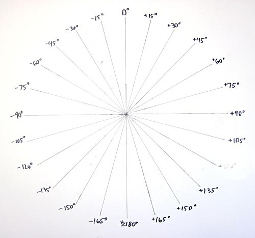 Image Credit: Ben Finio, Science Buddies / Science Buddies
Figure 17. Angle template ranging from 0° to +/- 180° in 15° increments.
- You will use this template to adjust the angle of your parabolic reflector. Place the router in the middle of the template so that when you look straight down from above the router, the antenna lines up exactly in the middle of the template, where all the lines intersect. From here, you can adjust the aim of the parabolic reflector to the left or the right. It may help your aim if you draw an arrow in the middle of the cardboard part of the parabolic reflector (from the focal point to the edge of the cardboard), as shown in Figure 18, below.
 Image Credit: Ben Finio, Science Buddies / Science Buddies
Figure 18. From left to right, parabolic reflector oriented at -45°, 0°, and +45°.
Testing your Parabolic Reflector
- Download and install a program for your wireless device (like a smartphone, tablet, or laptop) that can measure the signal strength of a wireless network. See the Materials section for suggestions.
- Take some time to familiarize yourself with the program. Read online documentation or help-files, or ask an adult for assistance.
- Some programs will show information about every available wireless network nearby — remember that you only want to measure the signal strength of your wireless router. Be sure you know the name of your wireless network so you can find it in the program's list.
- Make sure you know how to measure the wireless signal strength in dBm. As explained in the Introduction, the dBm readings should be negative numbers. Some programs may provide other scales — for example "signal quality" on a scale of 0–100 — but you should use dBm if possible. If dBm is not an option at all, then it is OK to use "signal quality" instead. You may need to read your program's documentation or help files, or ask an adult to help figure this out.
- Once you have located your wireless network and learned how to measure its signal strength in dBm, experiment with the program by walking around your house with your wireless device. Does the signal strength change? This will help you learn how to use the program and take readings before you do your experiment.
- Create a data table like Table 1, below, in your lab notebook. You will use this table to record your results. Your entries for the "control" rows may vary depending on the type of router you have. For example, if you have a router with two antennas, you can test it with only one antenna, and again with two antennas (in both cases without the parabolic reflector). If you purchased a USB Wi-Fi antenna for a laptop, you could measure the signal strength with the antenna (but no reflector), and the signal strength without the antenna, using the laptop's built-in wireless card.
| Signal strength (dBM) | ||||
|---|---|---|---|---|
| Angle | Trial 1 | Trial 2 | Trial 3 | Average |
| Control (no reflector, one antenna) | ||||
| Control (no reflector, two antennas) | ||||
| -180° | ||||
| -165° | ||||
| -150° | ||||
| ... | ||||
| +165° | ||||
| +180° | ||||
- Make sure the angle template you made is placed under your router, with the antenna centered in the middle of the template. Aim the parabolic reflector backward, at 180° (you may need to rotate the router itself slightly in order to do this — make sure the antenna stays centered).
- Stand roughly 5 meters (m) in front of your wireless router, along the 0° line of your angle template. Now, there are several additional variables you must be careful to keep constant for the course of your experiment:
- Distance from the router: It is OK if you do not stand exactly 5 m from the router. Ideally, you should be in the same room as the router without any walls in between, but it is OK if you have to go into a separate room, or be slightly farther away or closer to the router, based on the layout of your house. The important thing is to keep the distance and location you stand in constant for the entire experiment.
- Height of the wireless device: Hold the wireless device at the same height as your parabolic reflector. For example, if your router is sitting on a desk, you may need to hold the wireless device at about waist or chest level. If the router is on the floor, you may need to squat down and hold your wireless device closer to the floor.
- Orientation of the wireless device: Make sure you hold the wireless device in the same orientation for each trial. For example, if you are using a smartphone, do not switch between holding it horizontally and vertically. Pick one orientation and use it for the entire experiment.
- Use your Wi-Fi signal strength measurement program to take three readings of the signal strength in dBm. Record these readings for 180° in the table in you created in your lab notebook (note that -180° is the same as +180°, so you can enter the reading in both rows of the table).
- Adjust the angle of the parabolic reflector to the next row in your data table (-165°). If you have a volunteer to help, she or he can adjust the antenna while you continue to stand in the same place with your wireless device. Otherwise, adjust the parabolic reflector yourself, then return to the exact same place you were standing.
- Take three new readings and enter them in your data table. Note that -165° is not the same as +165° (that is only true for +⁄- 180°), so you should not duplicate the entry in your data table.
- Repeat steps 7 and 8 for each remaining angle in your data table.
- Remove the parabolic reflector from your wireless router's antenna. Take three final readings with your wireless device. These measurements are your control — they show you the baseline signal strength, without the use of a parabolic reflector. Comparing the readings with the parabolic reflector to the control will tell you whether the reflector made the signal strength better or worse. Remember to enter the three values in your data table.
- If your router originally had two antennas and you removed one, re-attach the second antenna. Take another set of three readings and enter them in a separate row in your data table. You can treat this as another set of control readings, or how your router performs in its "normal" state.
- For each row in your data table, calculate an average of the three values and enter it in the final column.
- Create a line graph with reflector angle (in degrees) on the x-axis and average signal strength (in dBm) on the y-axis. Also draw a horizontal line on the graph to represent the baseline signal strength with no reflector (you may need two lines if you took control readings with one and two antennas).
- Analyze your results.
- What are the effects of the parabolic reflector?
- How does signal strength vary with angle of the reflector?
- How does the signal strength with the reflector compare to the baseline signal strength at different angles? Are there some angles where the reflector improves the signal strength, and others where the reflector makes the signal weaker?
- Based on your results, in what situations do you think adding a parabolic reflector to an antenna would make sense? When would using a parabolic reflector be a bad idea?
- Remove the parabolic reflector from your router (or ask an adult if it is OK to continue using it). If you removed an antenna from your router, be sure to re-attach it.
Ask an Expert
Global Connections
The United Nations Sustainable Development Goals (UNSDGs) are a blueprint to achieve a better and more sustainable future for all.
Variations
- Repeat the experiment, testing other independent variables like distance from the antenna, or height or orientation of the wireless device.
- What is so special about a parabola? Can you use a reflector with a different shape instead? Try comparing two different reflector designs with each other.
- Do you think different materials found in your house might block the wireless signal? Check out the Science Buddies project What Materials Can Block a Wi-Fi Signal? to see how you can test how different materials can block a wireless signal.
- If your router has two external antennas, what happens if you repeat the project without removing one of the antennas? Do you still see a change in signal strength when you use the parabolic reflector on one antenna? What if you build two parabolic reflectors, one for each antenna?
Careers
If you like this project, you might enjoy exploring these related careers:


