Abstract
Do you have trouble remembering when to stop playing and clean up? Have you ever had little kids throw a tantrum about cleaning up while you were babysitting? If so, this project is for you! You will convert a stuffed animal into a light-up activity timer. You can use the timer for different activities like play, exercise, or doing homework. What you use it for is up to you!
Summary
We recommend going through the first few tutorials on our How to Use an Arduino page before you try this project.
A kit is available from our partner Home Science Tools®. See the Materials section for details.
No issues
/-/https/i.ytimg.com/vi/M8e6T-Hc9wE/maxresdefault.jpg)
Objective
Design and build a light-up activity timer.
Introduction
You might think of circuits as "hard" parts made from metal or stiff plastic, but did you know that you can use flexible materials to build soft circuits? In this project you will put a force sensor into a stuffed animal (Figure 1). The force sensor detects when it is pressed on. This lets you bop the stuffed animal on the head to do something — like lighting up LEDs — instead of pushing a more traditional button or switch.
/-/https/www.sciencebuddies.org/cdn/Files/19917/12/light-up-arduino-activity-timer.jpg)
Figure 1. A stuffed animal with a force sensor hidden inside its head.
The type of force sensor you will use in this project is technically called a force sensitive resistor or FSR. Resistors resist the flow of electrical current. "Normal" resistors have a fixed amount of resistance, which is measured in a unit called ohms, abbreviated with the capital Greek letter Omega (Ω). As the name implies, the resistance of a force sensitive resistor changes when you press on it. You can learn how to use a force sensor with an Arduino in this video:
/-/https/i.ytimg.com/vi/r7oWtcE6QQc/maxresdefault.jpg)
The project instructions will show you how to use a force sensitive resistor to start a basic timer that lights up two LEDs. You can add many other features to your project, like more LEDs, buzzers, or even motors. See the How to Use an Arduino reference in the Bibliography for more Arduino tutorials about things you can add to your project.
Terms and Concepts
- Force sensor
- Force sensitive resistor (FSR)
- Resistor
- Resistance
- Ohms
- Omega (Ω)
Questions
- What is resistance?
- What is the difference between a force sensitive resistor and a regular resistor?
- What are some possible uses for your activity timer?
Bibliography
- Finio, B. (n.d.). How to Use an Arduino. Science Buddies. Retrieved October 3, 2023.
- Science Buddies Staff (n.d.). Engineering Design Process. Science Buddies. Retrieved October 3, 2023.
Materials and Equipment 
Recommended Project Supplies
/-/https/www.sciencebuddies.org/cdn/Files/19915/12/SB_ARDNSTR_web__01473.jpg)
-
Electronics Kit for Arduino, available from our partner Home Science Tools®.
- Note: This project will work with the Arduino UNO R3, UNO R4 Minima, UNO R4 WiFi, and compatible third-party boards.
- Additional male-female jumper wires (the Science Buddies kit comes with 5, this project requires at least 6)
- Additional LEDs in other colors (the Science Buddies kit comes with red)
- Force sensitive resistor
- Stuffed animal of your choice
- Scissors
- Tape
- Windows or Mac computer. See this page if you have a Chromebook. Your computer will need:
- Access to the Arduino IDE, either installed local version or web-based editor (note that Chromebooks can only use the web version). Watch this video for a comparison of the two options.
- USB port. The Science Buddies kit comes with a USB-A to B cable. The "B" end plugs into the Arduino and the "A" end plugs into your computer. You will need an adapter or different cable if your computer only has USB-C ports. Watch this video to learn about the different types of cables and adapters.
- Lab notebook
Disclaimer: Science Buddies participates in affiliate programs with Home Science Tools®, Amazon.com, Carolina Biological, and Jameco Electronics. Proceeds from the affiliate programs help support Science Buddies, a 501(c)(3) public charity, and keep our resources free for everyone. Our top priority is student learning. If you have any comments (positive or negative) related to purchases you've made for science projects from recommendations on our site, please let us know. Write to us at [email protected].
Experimental Procedure
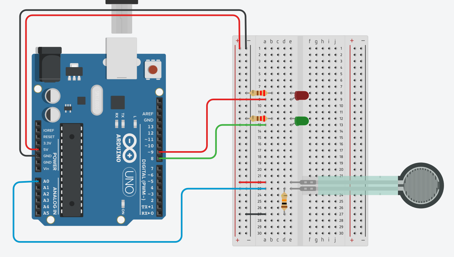
- Assemble your circuit on a breadboard as shown in Figure 2. You should test the circuit and code before you connect everything to your stuffed animal. You can also access a Tinkercad Circuits simulation of the circuit here.
- Red LED
- Positive side (longer lead) to Arduino pin 9
- Negative side (shorter lead) to ground through a 220 Ω resistor
- Green LED
- Positive side (longer lead) to Arduino pin 8
- Negative side (shorter lead) to ground through a 220 Ω resistor
- Force sensor
- One pin to 5 V
- Other pin to Arduino pin A0
- 10 kΩ resistor
- One lead to the force sensor pin that is connected to Arduino pin A0
- Other lead to ground
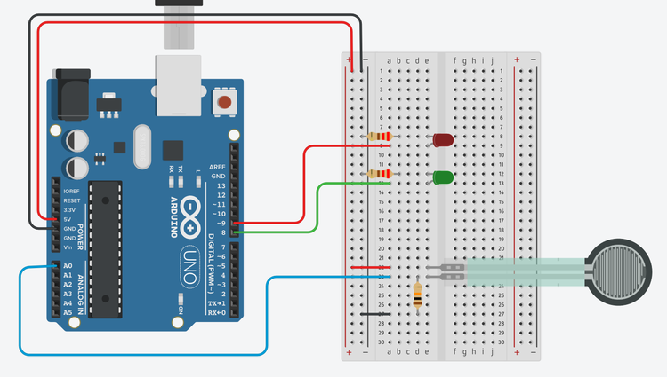
Figure 2. Breadboard diagram of the circuit. (Click to download a larger version of the diagram.) - Red LED
- Download arduino_activity_timer.ino. Open the file and read through the commented code so you understand how it works.
- Upload the file to your Arduino and open the serial monitor in the Arduino IDE (Tools → Serial monitor).
- Watch the serial monitor as you gently press on the force sensor. When the sensor reading goes above 500, the green LED should turn on.
- Wait for one minute, then the green LED should turn off and the red LED should turn on.
- After one more minute, both LEDs should turn off, and you can restart the timer by pressing the force sensor again. Make sure your circuit is working properly before you continue.
- Mount the LEDs and force sensor on your stuffed animal. You can do this by using male-female jumper wires to connect the parts to the breadboard (Figure 3). You can poke small holes in the stuffed animal for the legs of the LEDs, and cut a small slit to insert the force sensor just below the surface (Figure 4). Since the connections to the female ends of the jumper wires can fall out easily, you may want to secure them with tape.
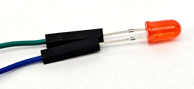
Figure 3. Legs of an LED pressed into the female ends of jumper wires.
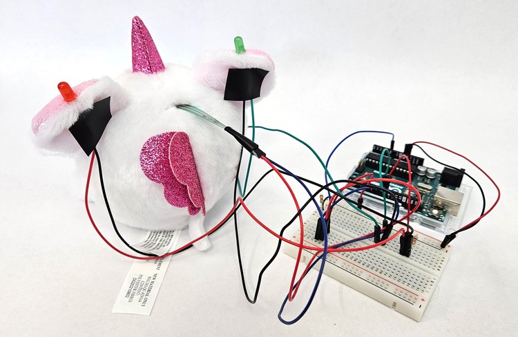
Figure 4. Rear view of the stuffed animal. The LED legs are poked through small holes in the ears. The force sensor is placed into a small slit at the top of the head. All the parts are connected to the breadboard with male-female jumper wires and the connections are secured with tape. - Re-upload the code or press the reset button on your Arduino. Gently press on the stuffed animal directly above where you put the force sensor and watch the serial monitor. If you need to press too hard to start the timer, decrease the sensor_threshold variable in the code, re-upload the program, and try again.
- After you have the basic circuit working, think about what else you can add to your project. See the Variations section for some suggestions.
- Conduct some real-world testing with your timer. Try using it yourself for an activity like playing, doing homework, or exercising. Then, ask other people to use it and ask for their feedback. What changes or improvements can you make to the design based on your real-world testing?
/-/https/www.sciencebuddies.org/cdn/Files/19919/10/arduino-activity-timer-breadboard.png)
/-/https/www.sciencebuddies.org/cdn/Files/19920/12/LED-female-jumper-wires.jpg)
/-/https/www.sciencebuddies.org/cdn/Files/19921/12/arduino-activity-timer-breadboard-wires.jpg)
Ask an Expert
Variations
- Can you add a third LED (usually a different color, like yellow) that turns on as a "warning" for a set period of time before the red LED turns on?
- Can you add a buzzer to your timer? This can be helpful in a busy classroom or when people are not looking at the timer.
- Can you add a motor to your project to make your stuffed animal move?
- Flex sensors are very similar to force sensors. Can you use one instead of (or in addition to) a force sensor?
- Can you add controls, like buttons or potentiometers, so the user can adjust the delay times without needing to change and re-upload the code?
- Add an LCD display to your activity timer so you know exactly how much time is remaining. See our Make a Pomodoro Study Clock project for instructions.
Careers
If you like this project, you might enjoy exploring these related careers:
/-/https/careerdiscovery.sciencebuddies.org/cdn/Files/1223/17/iStock-971549326.jpg)
/-/https/careerdiscovery.sciencebuddies.org/cdn/Files/1147/17/unsplash-fJebhGIP0P4.jpg)
/-/https/careerdiscovery.sciencebuddies.org/cdn/Files/1163/18/pexels-photo-1181472.jpg)
Contact Us
Our kits are developed in partnership with Home Science Tools®. If you have purchased a kit for this project, Home Science Tools® is pleased to answer any questions.In your email, please follow these instructions:
- Include your Home Science Tools® order number.
- Please describe how you need help as thoroughly as possible:
Examples
Good Question I'm trying to do Experimental Procedure step #5, "Scrape the insulation from the wire. . ." How do I know when I've scraped enough?
Good Question I'm at Experimental Procedure step #7, "Move the magnet back and forth . . ." and the LED is not lighting up.
Bad Question I don't understand the instructions. Help!
Good Question I am purchasing my materials. Can I substitute a 1N34 diode for the 1N25 diode called for in the material list?
Bad Question Can I use a different part?
Contact Support

/-/https/img.youtube.com/vi/hcPOTrnRzFU/0.jpg)
/-/https/img.youtube.com/vi/AGZxMfAWGiE/0.jpg)
/-/https/img.youtube.com/vi/rzEYT7V-yUk/0.jpg)