Abstract
In the animal kingdom, many different critters use whiskers to help them find their way around in the dark, through murky waters, or even to help them hunt prey. Whiskers can be very useful when the animals cannot rely on sight. Did you know that you can also build a robot that uses "whiskers" to find its way around? This project will show you how to build a simple robot that uses whiskers as "bump sensors" to help the robot detect when it is about to bump into an obstacle, so it can turn around and avoid crashing. Can you design a robot that can drive around on its own without crashing and getting stuck?
Summary
You will need to know how to use a breadboard to do this project. See the Science Buddies reference How to Use a Breadboard for Electronics and Circuits if you have not used a breadboard before.
A kit is available from our partner Home Science Tools®. See the Materials section for details.
Short circuits can get very hot and present a burn hazard. Be careful to avoid short circuits when building your robot. See the Procedure for more information.
/-/https/i.ytimg.com/vi/JGSLAD8NDRA/maxresdefault.jpg)
Objective
Build a basic obstacle-avoiding robot and improve the design to help it avoid getting stuck.
Introduction
Have you ever gotten up to go to the bathroom in the middle of the night and stubbed your toe or hit your shin on a piece of furniture in the dark? It hurts! As humans, we rely heavily on our eyesight to get around. Many other animals are active at night, swimming through murky waters, or crawling into tiny, dark spaces where relying on eyesight is not a good option. Some of them evolved whiskers to help them "feel" their way around in the dark by detecting nearby surfaces, air currents, or even to help them hunt for prey.
What does this have to do with robots, you ask? Engineers want to design robots that are autonomous, meaning they can move around on their own without direct human control. One important part of autonomous operation is avoiding crashing into things. In robotics, this is called obstacle avoidance. Using a camera and a computer to let a robot "see" obstacles with computer vision can be complicated and expensive. One much simpler approach is to use the robotic equivalent of whiskers that stick out from either side of the robot, like the ones shown in Figure 1. These whiskers can be used to detect obstacles and make the robot turn away before it crashes. Figure 1 shows a picture of the robot. Watch the video for a demonstration.
/-/https/www.sciencebuddies.org/cdn/Files/7370/9/bluebot-obstacle-avoiding.jpg)
Figure 1. The obstacle-avoiding robot you will build in this project.
Can you figure out how the robot works, based on watching the video? The robot has two wheels attached to motors (and a third "roller" wheel that keeps it from falling over). The direction in which the wheels spin can be used to steer the robot. Normally, both wheels spin forward, which causes the robot to move forward. However, when a whisker bumps into an obstacle, it causes the wheel on the opposite side of the robot to spin backwards. This makes the robot steer away from the obstacle. Figure 2 illustrates this concept.
/-/https/www.sciencebuddies.org/cdn/Files/7371/9/bump-robot-steering.png)
A robot with whiskers moves forward when both whiskers are untouched. When the left whisker bumps into an object, the right wheel of the robot is put into reverse which will cause the robot to turn right and avoid the object. The inverse is true if the right whisker bumps into an object, the robot will turn left. If both whiskers bump into an object both wheels are spun in reverse and the robot backs up.
Figure 2. A diagram showing how the obstacle-avoiding robot steers. The blue arrows represent the direction in which the wheels spin. When neither whisker detects an obstacle, both wheels spin forward and the robot drives forward (top image). When the left whisker hits something, the left wheel keeps spinning forward, but the right wheel spins backward, causing the robot to turn right (left image). The opposite is true for the right whisker (right image). If both whiskers hit obstacles, the robot will go in reverse (bottom image).
How do the whiskers make the wheels spin in one direction or the other? This depends on an electrical circuit. A circuit is a path through which electricity can flow. Circuits can be very simple, like a battery that lights up a single lightbulb, or very complicated, like the kind inside your computer. In this robot, a circuit uses electrical signals from the whiskers to control two motors that drive the wheels. Figure 3 shows a flow chart for how the robot works.
/-/https/www.sciencebuddies.org/cdn/Files/6658/11/obstacle-avoiding-robot-block-diagram.png)
Figure 3. A flow chart showing how the robot works. Whiskers provide input signals to a circuit that controls motors, which turn wheels and make the robot move.
In this science project, you will follow step-by-step directions to build a basic obstacle-avoiding robot, like the one shown in the video. The robot is able to drive around and automatically avoid some obstacles by turning away from them. However, the robot is not perfect. Sometimes it will get stuck, especially if it drives straight into an obstacle that was directly ahead (so neither whisker detects it). Your goal will be to use the engineering design process to improve your robot and help it avoid getting stuck.
While previous experience with electronics will be helpful in building the robot, it is not required. If you would like to get started building your robot right away, you can move on to the Procedure. For more information about how the robot works and what the different parts of the circuit do, continue reading the rest of the Introduction. For a detailed explanation of the robot's circuit (for advanced students or robotics/electronics hobbyists), including a complete circuit diagram, see the Help section.
Technical Note
The rest of the Introduction contains more details about the electronic components used in the circuit. The following information is provided as a reference, and you do not need to fully understand it in order to do the project. If are ready to just start building the robot, you can move on to the Procedure.
If you would like to read the rest of the Introduction, it will help if you are familiar with basic electronics terms like voltage, current, and resistance. Science Buddies has many beginner and intermediate level electronics projects, an Electronics Primer, and a Electricity, Magnetism, & Electromagnetism Tutorial that can help you learn more about these topics. You can also refer to the Bibliography for more information.
For a complete technical explanation of how the circuit works, including a circuit diagram, see the Help section.
The circuit you will build in this project involves a variety of electronic components. All of the components are combined on a chassis, or plastic base for the robot, which includes wheels. Some of the components, like batteries and switches, you probably use every day (even if you do not notice it). Others, like an H-bridge, might be new to you if you have not done an electronics project before. Table 1 has pictures and descriptions of each component you will use in this project. For a more detailed explanation of what each component does in the circuit, see the Help section.
| Item Name | Picture | Description |
|---|---|---|
| Battery pack | This is the power supply for your robot. Battery packs come in all shapes and sizes. The one in this project holds 4 AA batteries. | |
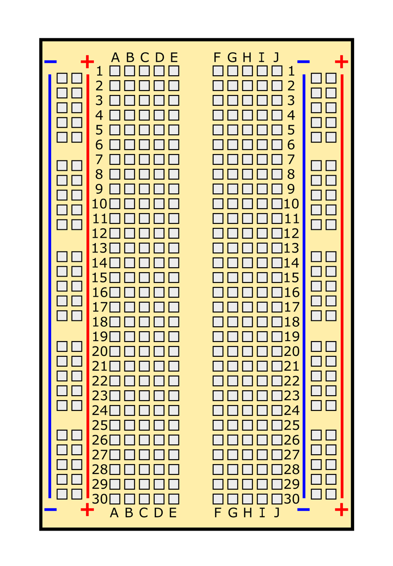
| Breadboard |
/-/https/www.sciencebuddies.org/cdn/Files/7158/11/breadboard-picture.jpg) |
A breadboard allows you to quickly and easily connect wires and electronic components in order to build a circuit. The connections are not permanent, so you can easily move things around if you make a mistake. |
| Switch | You use switches every day to turn lights and appliances on and off. This is a tiny switch that fits on a breadboard, to let you turn your robot on and off. | |
| Jumper wire |
/-/https/www.sciencebuddies.org/cdn/Files/6283/12/jumper-wires.jpg) |
Jumper wires are short wires used to make electrical connections on a breadboard. They come with many colors of plastic insulation, which makes it easy to color-code and organize complicated circuits. |
| DC Motor | Electrical current causes a motor to spin. Two motors drive the robot's wheels. This type of motor runs on direct current (DC) from a battery (as opposed to alternating current [AC] from a wall outlet). | |
| H-bridge | An H-bridge is a special type of chip designed to allow bi-directional control of a DC motor. This is unlike a MOSFET (used in the other robotics projects listed in the Make It Your Own section), which only allows a motor to spin in one direction. | |
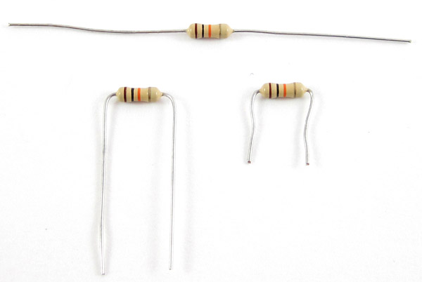
| 10 kΩ resistor |
/-/https/www.sciencebuddies.org/cdn/Files/6313/17/resistor.jpg) |
A resistor resists the flow of electrical current. In this project the resistors are used as "pull down" resistors that "pull" the value of a pin on the H-bridge down to 0 V. |
| Lever switch |
/-/https/www.sciencebuddies.org/cdn/Files/7372/12/lever-switch.jpg) |
Two lever switches act as your robot's bump sensors. Electrically, they work the same as the robot's power switch, but the physical shape is different; they have long levers that act like "whiskers" to detect when the robot bumps into something. |
/-/https/www.sciencebuddies.org/cdn/Files/7144/26/spdt-switch-new.jpg)
Table 1. Pictures and descriptions of each circuit component used in this project.
Terms and Concepts
General electronics and robotics terms:
- Whisker
- Autonomous
- Obstacle avoidance
- Circuit
- Voltage
- Current
- Resistance
- Chassis
Circuit components:
- Battery pack
- Breadboard
- Switch
- Jumper wire
- DC motor
- Male-female jumper wire
- Bump sensor
- Digital logic
- H-bridge
- Dual in-line package (DIP)
Questions
- How do animals use whiskers? What advantages do whiskers provide?
- How are antennae similar to whiskers and how are they different? What types of animals have whiskers, and what types have antennae?
- What are some different methods robots use for obstacle avoidance?
- Can you find some real-life examples online of obstacle-avoiding robots?
Bibliography
Check out this reference if you want to learn more about how whiskers work in animals:
- Price, J. (2012, June 27). Whiskers: why do animals have whiskers and how do they work? Discover Wildlife. Retrieved November 17, 2023.
These beginner references will be useful if you are just starting out with electronics and robotics:
- Science Buddies Staff. (n.d.). How to Use a Breadboard. Retrieved June 23, 2016.
- Science Buddies Staff (n.d.). Electronics Primer: Introduction. Retrieved September 8, 2015.
These references will be useful for students who want to learn more about how the circuit works, and about electronics in general:
- Lindblom, J. (n.d.). How to Read a Schematic. SparkFun Electronics. Retrieved October 16, 2014.
- Taylor, C. (n.d.). Voltage, Current, Resistance, and Ohm's Law. SparkFun Electronics. Retrieved October 16, 2014.
These references contain specific information about some of the circuit components and concepts used in this project:
- Lindblom, J. (n.d.). Resistors. SparkFun Electronics. Retrieved October 16, 2014.
- Clark, A. (n.d.). Pull-up Resistors. SparkFun Electronics. Retrieved October 16, 2014.
- Hord, M. (n.d.). Digital Logic. SparkFun Electronics. Retrieved October 16, 2014.
- Wikipedia contributors. (2014, September 13). H-bridge. Wikipedia: The Free Encyclopedia. Retrieved October 16, 2014.
- Texas Instruments. (2004 November). L293, L293D Quadruple Half-H Drivers. Retrieved October 20, 2014.
Materials and Equipment 
Recommended Project Supplies
/-/https/www.sciencebuddies.org/cdn/Files/9118/11/bluebot-motion-activated-googly-1100_1.png)
- BlueBot: 4-in-1 Robotics Kit, available from our partner Home Science Tools®. See Table 1 in the Introduction for pictures if you are not sure what a part looks like. You will need these items from the kit (the kit also contains additional parts for three other projects):
- Blue plastic robot chassis (includes wheels, motors, and 4xAA battery holder)
- AA batteries (4)
- Breadboard
- Jumper wire kit
- Power switch
- L293DN H-bridge motor driver
- 10 kΩ resistors (4) (brown, black, orange, gold stripes)
- Lever switches (2)
- You will also need to gather these items, not included in the kit:
- Double-sided foam tape
- Scotch® tape or glue
- Popsicle sticks (2)
- Scissors
- Materials to make an "obstacle course" or arena for your robot, like stacks of books or small cardboard boxes. Note that the cardboard boxes will need something heavy inside to weigh them down, or else the robot might just push them around.
- Optional: Wire cutters (can be used to shorten the metal leads on some parts of your circuit, making the circuit "neater")
- Optional: Needle-nose pliers or tweezers (make it easier to handle small circuit components)
- Lab notebook
Disclaimer: Science Buddies participates in affiliate programs with Home Science Tools®, Amazon.com, Carolina Biological, and Jameco Electronics. Proceeds from the affiliate programs help support Science Buddies, a 501(c)(3) public charity, and keep our resources free for everyone. Our top priority is student learning. If you have any comments (positive or negative) related to purchases you've made for science projects from recommendations on our site, please let us know. Write to us at [email protected].
Experimental Procedure
Assembling Your BlueBot Chassis
- Follow the instructions in the video to assemble your robot chassis.
- Your kit comes with printed directions for assembling the chassis, but we recommend watching the video so you fully understand how all the parts fit together.
- The blue plastic parts come with a thin layer of protective plastic coating. Peel this coating off before assembling your chassis.
- We also recommend using double-sided foam tape to attach the battery holder to the top of the chassis, as shown in Figure 4. The printed directions recommend putting the battery holder in-between the two chassis plates, but this makes it harder to change the batteries.
- You will have some extra parts when you are done, including screws, nuts, and blue plastic gears. Put these parts aside for now; you will not need them for this project.
/-/https/i.ytimg.com/vi/SBeGl_IgWwY/maxresdefault.jpg)
/-/https/www.sciencebuddies.org/cdn/Files/7136/33/bluebot-chassis-assembled.jpg)
Figure 4. A completed BlueBot chassis with breadboard and battery pack on top.
Assembling Your Circuit
- To build your circuit, you will need to know how to use a breadboard. Watch the video and see the Science Buddies reference How to Use a Breadboard for Electronics and Circuits.
/-/https/i.ytimg.com/vi/MtiJz7gh1VU/maxresdefault.jpg)
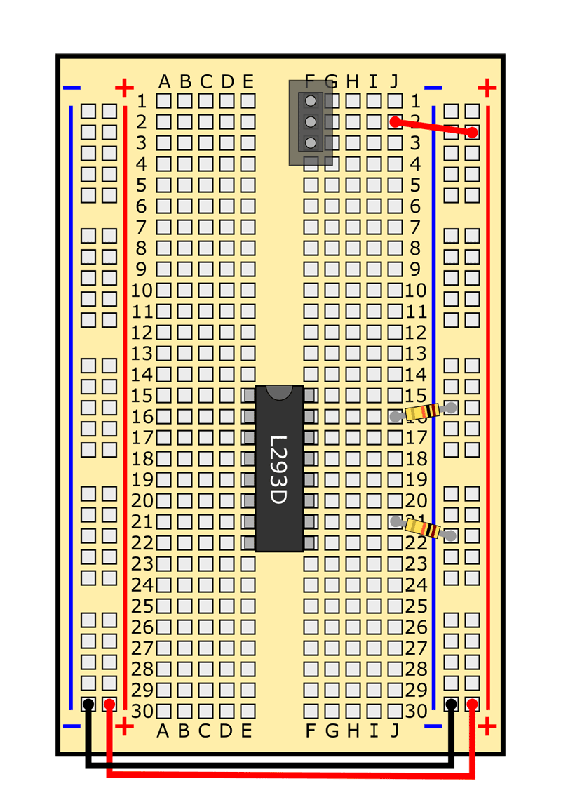
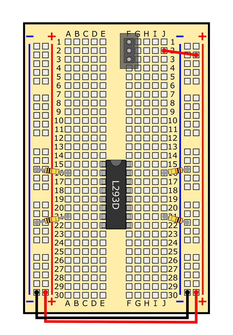
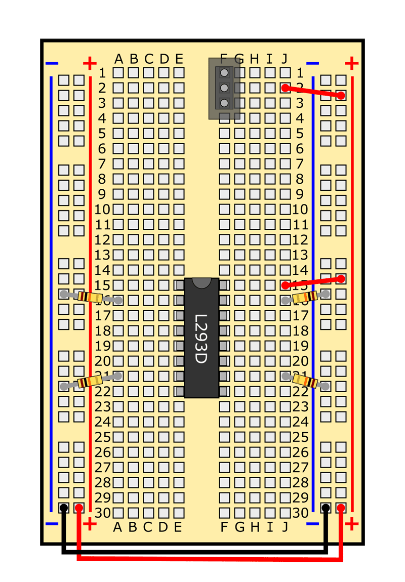
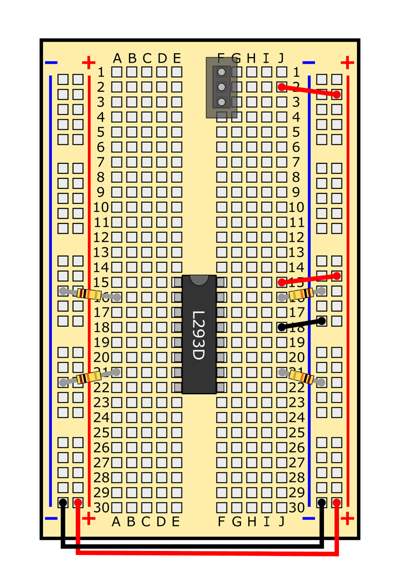
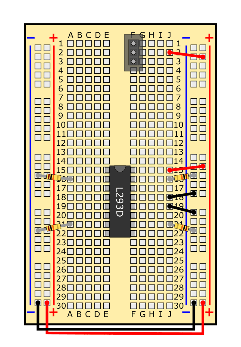
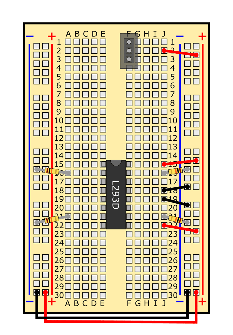
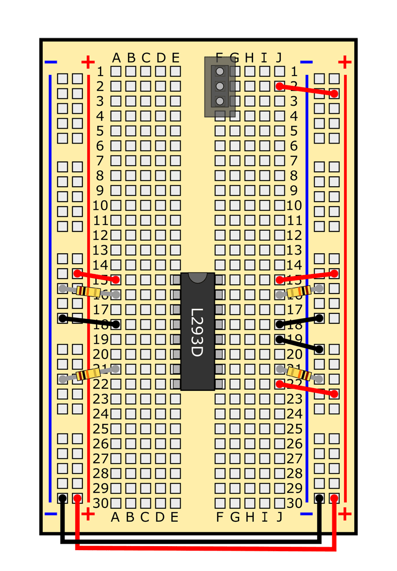
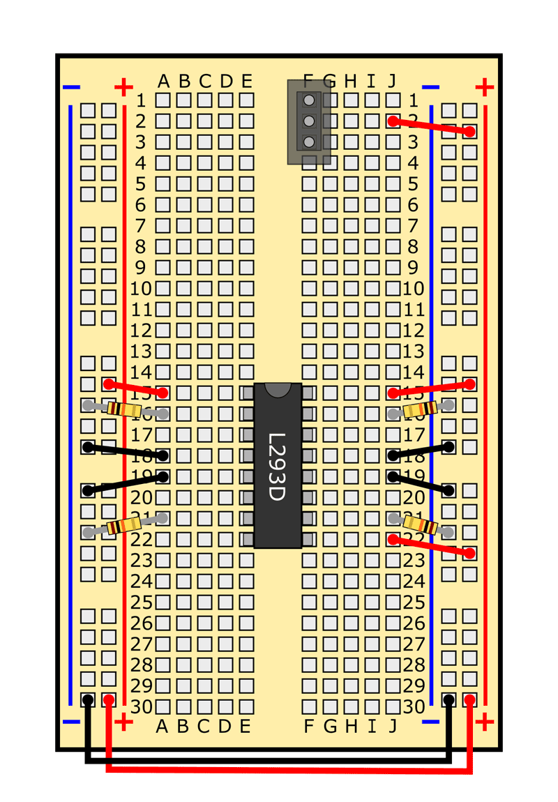
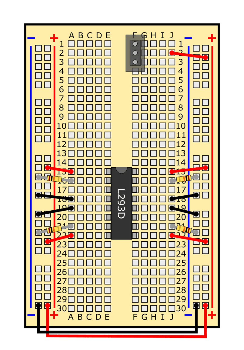
- Now that you know how to use a breadboard, you are ready to assemble your BlueBot circuit. Table 2 shows a list of all the components in the circuit and where they go on the breadboard. You can download and print a PDF of this table—complete with checkboxes to track each step—to use while you are building your robot. You can also view a slideshow that shows breadboard diagrams of the circuit. Follow along in the table and/or slideshow to build your circuit one component at a time. Your finished circuit should look like the one in Figure 5. Pay attention to these notes:
- Remember to push all components firmly into the breadboard.
- All references to orientation (up, down, left, and right) assume you have the breadboard "right-side up," so the writing is facing you.
- Your jumper wire kit comes with an assortment of colors, and the colors may vary. It does not matter what color jumper wires you use. Your colors do not need to match the colors in the diagrams. In general, you should use the shortest wires possible, to help keep your circuit neat.
- Your lever switches act as bump sensors, so they need to be mounted on the front of your robot, not on the breadboard. You also need to attach popsicle sticks to the levers to extend the robot's "whiskers." See Figures 6 and 7 for instructions on how to mount the lever switches to your robot's chassis.
- Insert the batteries last. If you see or smell smoke when you insert the batteries, you have a short circuit somewhere. Immediately remove the batteries and re-check your wiring.
| Component | Picture | Symbol | Breadboard holes | Note |
|---|---|---|---|---|
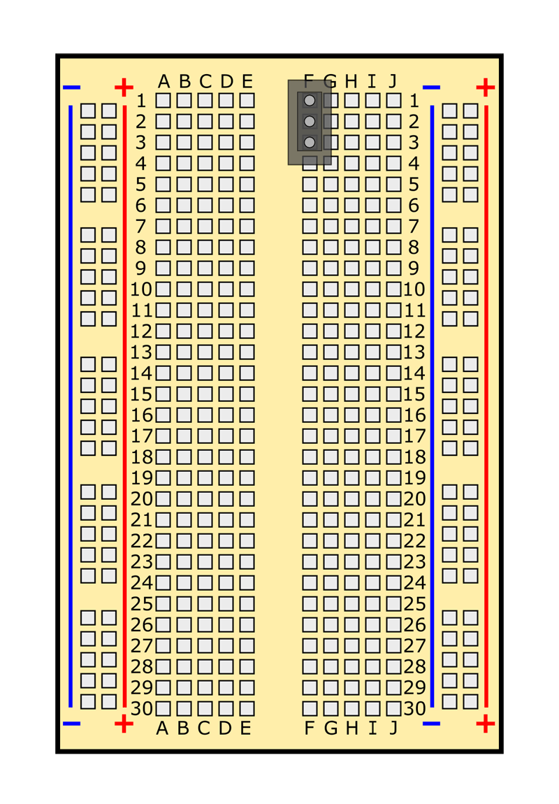
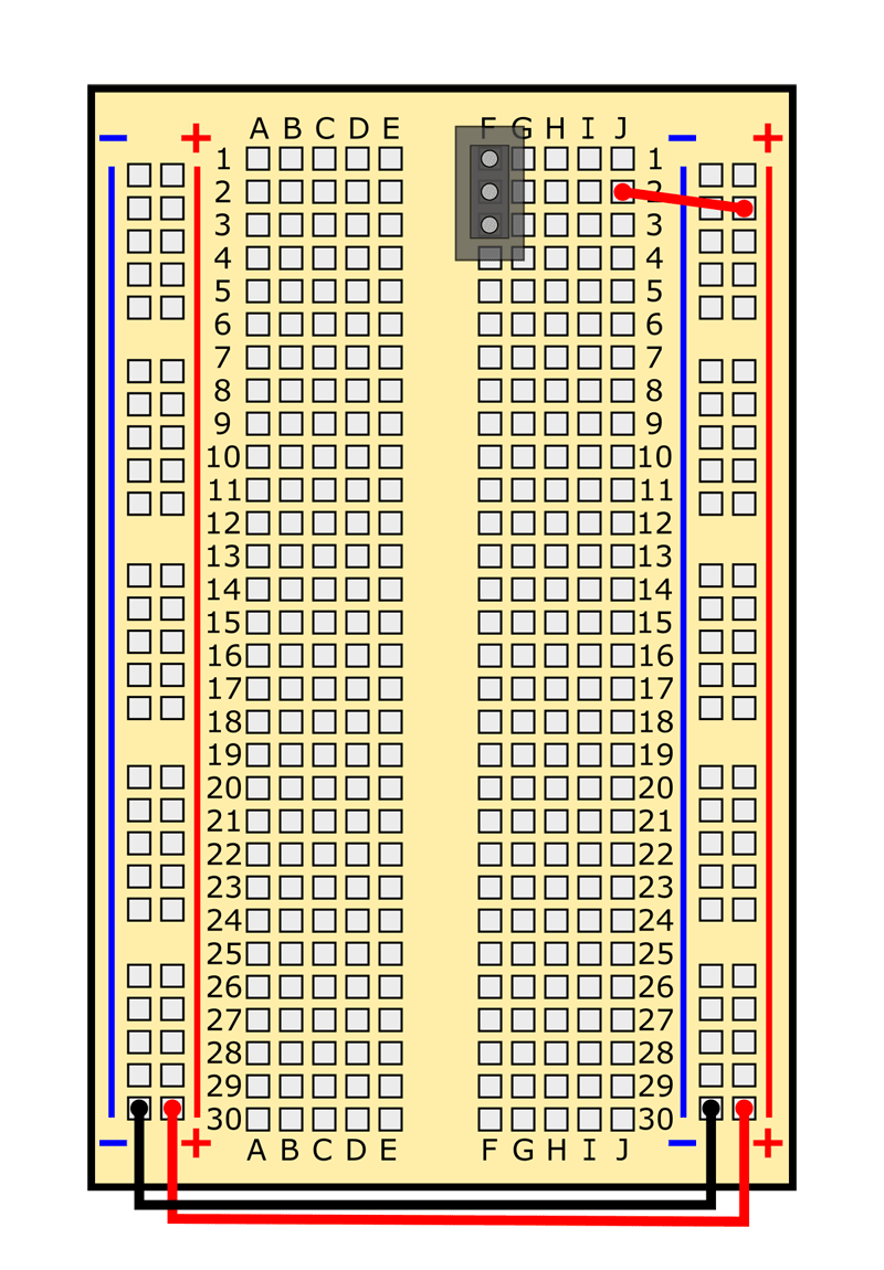
| Power switch | F1, F2, F3 | The direction in which it is facing does not matter, but make sure to slide the switch down (toward row 30, away from row 1), this is the "off" position. | ||
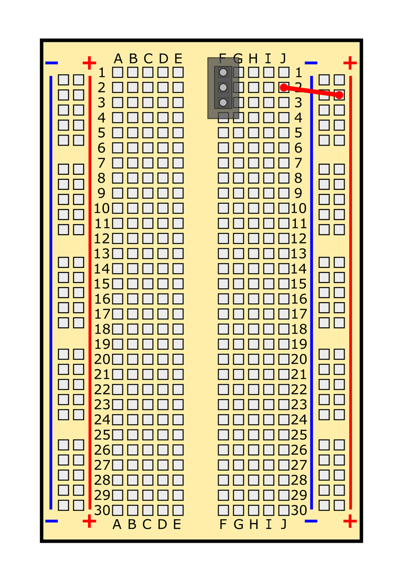
| Jumper wire | J2 to (+) bus | Color does not matter. | ||
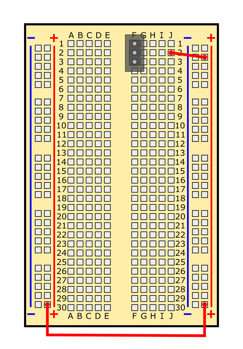
| Jumper wire | Left side (+) bus to right side (+) bus | Color does not matter. | ||
| Jumper wire | /-/https/www.sciencebuddies.org/cdn/Files/7145/12/jumper-wire-picture.jpg) |
/-/https/www.sciencebuddies.org/cdn/Files/7146/11/jumper-wire-symbol.png) |
Left side (-) bus to right side (-) bus | Color does not matter. |
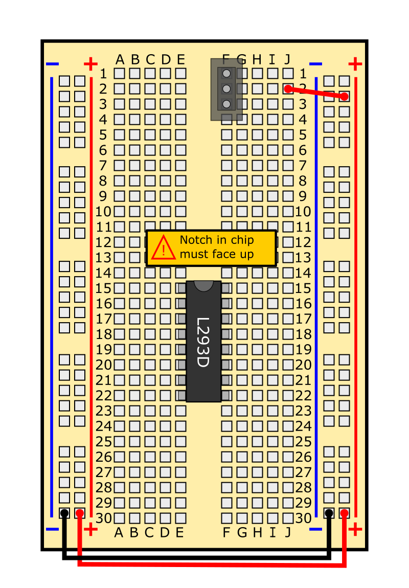
| H-bridge motor driver | /-/https/www.sciencebuddies.org/cdn/Files/6661/19/L293D-h-bridge.png) |
/-/https/www.sciencebuddies.org/cdn/Files/6681/11/H-bridge-breadboard.png) |
Left side: holes E15 to E22 Right side: holes F15 to F22 |
The semi-circular "notch" in one end of the chip must face up (towards row 15). You may need to bend the pins together slightly to get them to fit into the breadboard. Note: the writing on your H-bridge might not match the picture exactly. This is OK. |
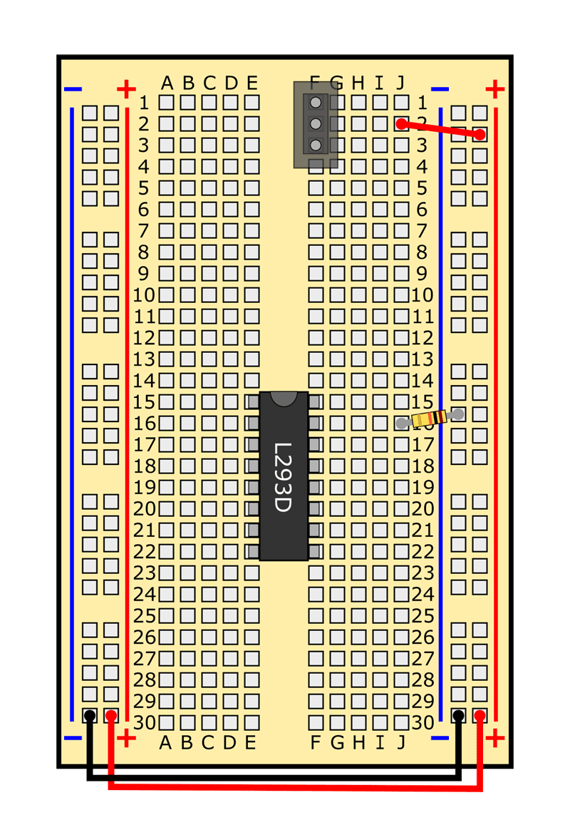
| 10 kΩ resistor | /-/https/www.sciencebuddies.org/cdn/Files/7373/9/10k-resistor.jpg) |
/-/https/www.sciencebuddies.org/cdn/Files/7374/9/10k-resistor-symbol.png) |
J16 to (-) bus | Brown, black, orange, gold stripes. Direction does not matter. |
| 10 kΩ resistor | |
|
J21 to (-) bus | Brown, black, orange, gold stripes. Direction does not matter. |
| 10 kΩ resistor | |
|
A16 to (-) bus | Brown, black, orange, gold stripes. Direction does not matter. |
| 10 kΩ resistor | |
|
A21 to (-) bus | Brown, black, orange, gold stripes. Direction does not matter. |
| Jumper wire | J15 to (+) bus | Color does not matter. | ||
| Jumper wire | J18 to (-) bus | Color does not matter. | ||
| Jumper wire | J19 to (-) bus | Color does not matter. | ||
| Jumper wire | J22 to (+) bus | Color does not matter. | ||
| Jumper wire | A15 to (+) bus | Color does not matter. | ||
| Jumper wire | A18 to (-) bus | Color does not matter. | ||
| Jumper wire | A19 to (-) bus | Color does not matter. | ||
| Jumper wire | A22 to (+) bus | Color does not matter. | ||
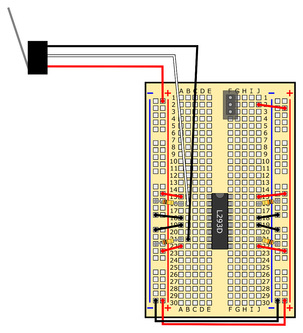
| Top lever switch | |
/-/https/www.sciencebuddies.org/cdn/Files/7375/9/lever-switch-symbol.png) |
Red wire to (+) bus Black wire to B21 White wire to B16 |
See Figures 6 and 7 for mounting instructions. |
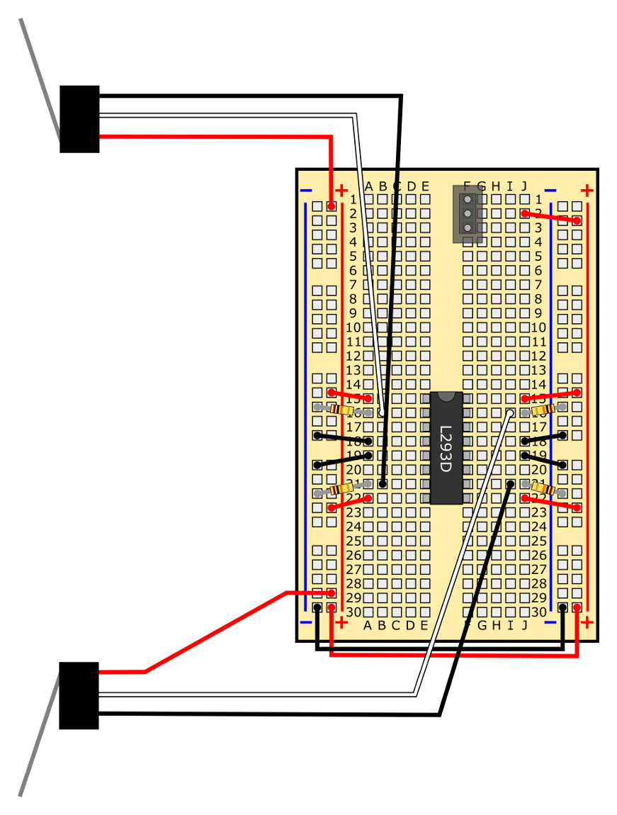
| Bottom lever switch | |
|
Red wire to (+) bus Black wire to I21 White wire to I16 |
See Figures 6 and 7 for mounting instructions. |
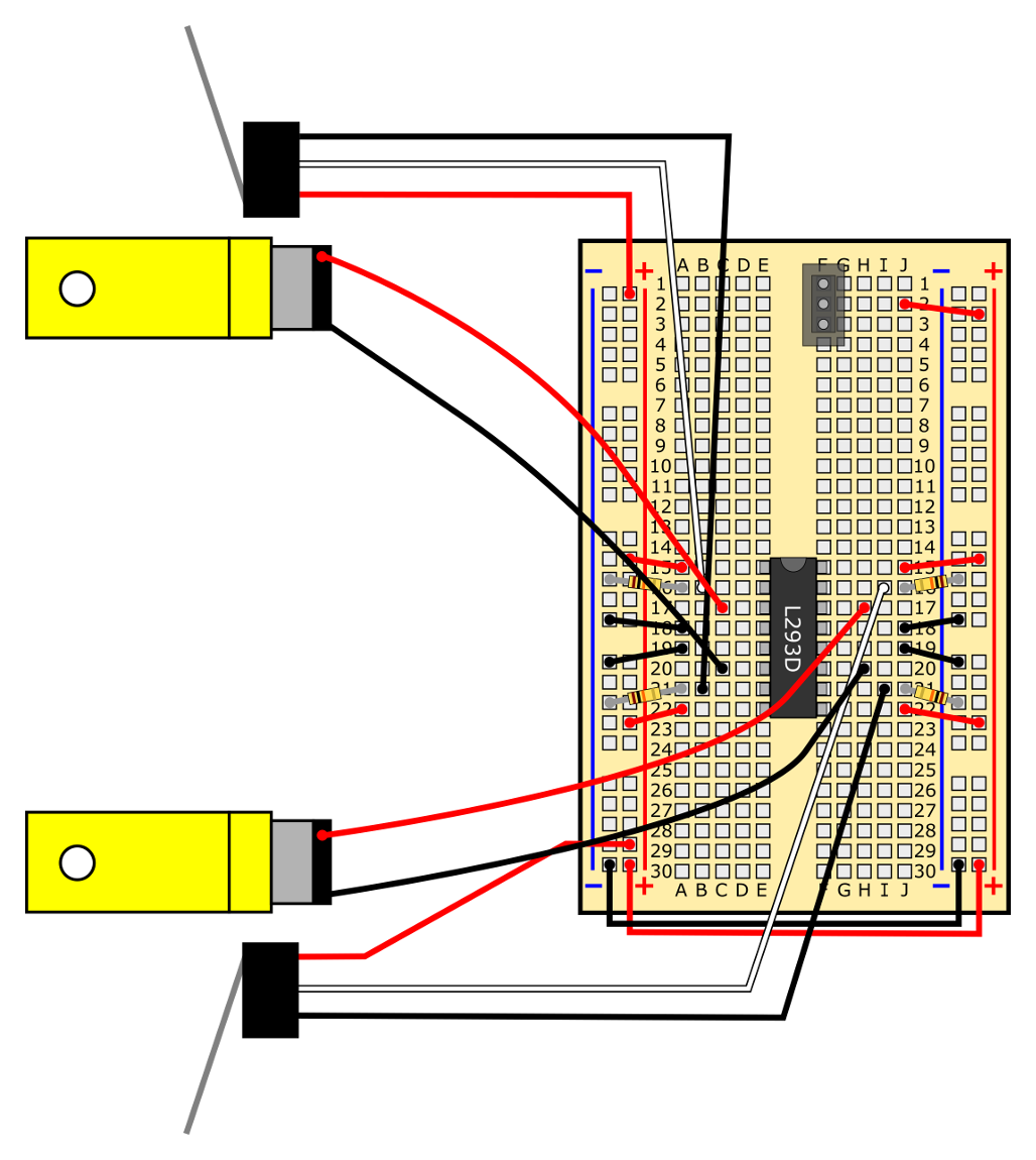
| Top motor | /-/https/www.sciencebuddies.org/cdn/Files/7152/72/DC-motor-picture.jpg) |
/-/https/www.sciencebuddies.org/cdn/Files/7153/25/motor-symbol.png) |
Red lead to C17 Black lead to C20 |
When the robot is driving forward, this is the "right" motor. |
| Bottom motor | |
|
Red lead to H17 Black lead to H20 |
When the robot is driving forward, this is the "left" motor. |
| Battery holder | /-/https/www.sciencebuddies.org/cdn/Files/7154/72/4xAA-battery-holder-picture.jpg) |
/-/https/www.sciencebuddies.org/cdn/Files/7155/10/battery-holder-symbol.png) |
Red lead to J1 Black lead to (-) bus |
Do not insert batteries until circuit is complete. |
| AA battery | /-/https/www.sciencebuddies.org/cdn/Files/7156/25/AA-battery-picture.jpg) |
/-/https/www.sciencebuddies.org/cdn/Files/7157/25/battery-symbol.png) |
N/A | Insert into battery holder. Make sure (+) signs on batteries line up with (+) signs in battery holder. |
/-/https/www.sciencebuddies.org/cdn/Files/7143/12/switch-symbol.png)
Table 2. List of circuit components and locations. A printable PDF version is available.
/-/https/www.sciencebuddies.org/cdn/Files/7401/12/obstacle-avoiding-robot-circuit.png)
/-/https/www.sciencebuddies.org/cdn/Files/7380/6/slideshow-1-obstacle-avoiding-robot-circuit.png)
/-/https/www.sciencebuddies.org/cdn/Files/7381/6/slideshow-2-obstacle-avoiding-robot-circuit.png)
/-/https/www.sciencebuddies.org/cdn/Files/7382/7/slideshow-3-obstacle-avoiding-robot-circuit.png)
/-/https/www.sciencebuddies.org/cdn/Files/7383/7/slideshow-4-obstacle-avoiding-robot-circuit.png)
/-/https/www.sciencebuddies.org/cdn/Files/7384/12/obstacle-avoiding-slide-6.png)
/-/https/www.sciencebuddies.org/cdn/Files/7385/7/slideshow-6-obstacle-avoiding-robot-circuit.png)
/-/https/www.sciencebuddies.org/cdn/Files/7386/6/slideshow-7-obstacle-avoiding-robot-circuit.png)
/-/https/www.sciencebuddies.org/cdn/Files/7387/6/slideshow-8-obstacle-avoiding-robot-circuit.png)
/-/https/www.sciencebuddies.org/cdn/Files/7388/6/slideshow-9-obstacle-avoiding-robot-circuit.png)
/-/https/www.sciencebuddies.org/cdn/Files/7390/6/slideshow-11-obstacle-avoiding-robot-circuit.png)
/-/https/www.sciencebuddies.org/cdn/Files/7391/6/slideshow-12-obstacle-avoiding-robot-circuit.png)
/-/https/www.sciencebuddies.org/cdn/Files/7392/6/slideshow-13-obstacle-avoiding-robot-circuit.png)
/-/https/www.sciencebuddies.org/cdn/Files/7393/6/slideshow-14-obstacle-avoiding-robot-circuit.png)
/-/https/www.sciencebuddies.org/cdn/Files/7394/6/slideshow-15-obstacle-avoiding-robot-circuit.png)
/-/https/www.sciencebuddies.org/cdn/Files/7395/6/slideshow-16-obstacle-avoiding-robot-circuit.png)
/-/https/www.sciencebuddies.org/cdn/Files/7396/6/slideshow-17-obstacle-avoiding-robot-circuit.png)
/-/https/www.sciencebuddies.org/cdn/Files/7397/14/obstacle-avoiding-slide-20.png)
/-/https/www.sciencebuddies.org/cdn/Files/7398/12/obstacle-avoiding-slide-21.png)
/-/https/www.sciencebuddies.org/cdn/Files/7399/12/obstacle-avoiding-slide-22.png)
/-/https/www.sciencebuddies.org/cdn/Files/7400/12/obstacle-avoiding-slide-23.png)
/-/https/www.sciencebuddies.org/cdn/Files/7379/6/resistor-leads.jpg)
Slideshow with step-by-step instructions viewable online.
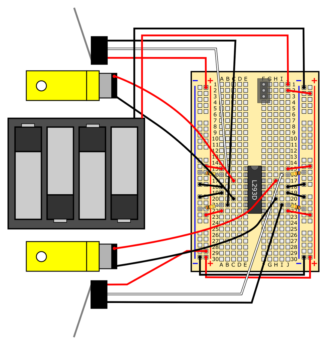
/-/https/www.sciencebuddies.org/cdn/Files/7376/9/obstacle-avoiding-robot-circuit.jpg)
Figure 5. Your completed circuit should look like this.
- Use double-sided foam tape to attach the lever switches to the front of your robot, and to attach popsicle sticks to the lever switches, as shown in Figures 6 and 7.
/-/https/www.sciencebuddies.org/cdn/Files/7377/9/mounting-lever-switches.jpg)
Figure 6. Use double-sided foam tape to mount the lever switches to the front of your robot. You can decide exactly where you want to put the switches; for example, whether you attach them to the top or bottom plate of the chassis. Note that you might end up adjusting them later.
/-/https/www.sciencebuddies.org/cdn/Files/7378/10/mount-popsicle-sticks.jpg)
Figure 7. Use tape to attach popsicle sticks to the metal arms of the lever switches to act as "whiskers."
Testing Your Robot
You are finally ready to start testing your robot! Remember that now you will need to follow the Engineering Design Process to get your robot working. Follow these steps to learn how to use your robot.
- Double-check your circuit against the breadboard diagrams in the previous section. Remember that just one misplaced wire can prevent the circuit from working properly.
- Hold the robot's chassis in one hand, so the wheels are off the ground.
- Turn the robot's power switch "on" by sliding it up, toward row 1 on the breadboard.
- Your robot's wheels should start spinning forward. If you press down on the popsicle stick attached to either lever switch, that should cause the wheel on the opposite side of the robot to spin backward. Check Table 3 to see what you should do next.
| Observation | What to do |
|---|---|
| I see or smell smoke. | Immediately turn your robot off. You have a short circuit somewhere. Recheck your wiring against the breadboard diagrams in the previous section. |
| Each wheel spins forward when I turn the robot on, and each wheel goes in reverse when I press the lever switch on the opposite side of the robot. | Your robot works! Move on to the next step. |
| One or both wheels spin backwards when I turn the robot on. | If a wheel is spinning backwards, reverse the red and black wires of that motor. See the Help section for more details. |
| The wheels spin when I turn the robot on, but do not change direction when I press the lever switches. | You have an error in your circuit somewhere. Re-check your circuit against the breadboard diagrams in the previous section. Remember that just one misplaced wire can prevent your circuit from working. |
| Pressing a lever switch causes the wheel on the same side of the robot to switch direction. | You have your two motors or your two lever switches' wires reversed. Swap one set of connections, but not both (for example, take the motor wires that are plugged in to the right side of your breadboard and switch them with the motor wires on the left side of your breadboard). |
| The wheels do not spin at all when I turn the robot on. | See the Help section for troubleshooting information. |
Table 3. Troubleshooting procedure for the first time you turn on your robot.
- Once you have your robot's circuit working, try putting it down on the floor and aiming it toward a wall at about a 45 degree angle. The robot should drive toward the wall, touch the wall with one of its "whiskers," then turn away and keep driving. You can also try putting your hand or foot in front of the robot's whiskers as it drives around, forcing it to turn.
- Your robot might not work perfectly; sometimes it might get stuck or fail to turn. This is where the engineering design process really comes into play. Think about what you can do to improve your robot. Here are some suggestions to get you started:
- Do the popsicle sticks come loose or fall off? Is the connection between the popsicle sticks and the lever switches sturdy enough?
- What happens if you change the position or angle of the lever switches? Is it better for the "whiskers" to be pointing straight out to the side, or angled slightly forward or backward?
- What happens if your robot drives straight into an obstacle, without hitting either whisker? Can you think of a way to fix this?
- Once you have your robot working, see if you can get it to navigate a more complicated "obstacle course" or maze. Can it automatically bounce off several obstacles and keep driving without getting stuck? Can you let it drive around a room in your house or school and just bounce off the existing furniture and walls? How long can it drive before it gets stuck? What other improvements could you make to help prevent the robot from getting stuck?
Troubleshooting
For troubleshooting tips, please read our FAQ: Build an Obstacle-Avoiding Robot (BlueBot Project #4).
Ask an Expert
Global Goals
The United Nations Sustainable Development Goals (UNSDGs) are a blueprint to achieve a better and more sustainable future for all.
/-/https/www.sciencebuddies.org/cdn/Files/19752/5/E-WEB-Goal-09.png)
Variations
- There are three other projects you can do with your BlueBot kit. Since you have already assembled your chassis, all you need to do is build a new circuit.
- The Arduino is a very popular type of microcontroller used in robotics. It lets you write a computer program that can read inputs from sensors and use them to control motors. This gives you more precise "control" over your robot's behavior. For example, when one or both whiskers detect an obstacle, you could tell the robot to go in reverse for a few seconds instead of turning immediately; this could help prevent the robot from getting stuck. Can you build a programmable obstacle-avoiding robot by adding an Arduino to your chassis? See our How to Use an Arduino page to learn more.
Explore More!
Looking for more robot fun? Explore the World of Robotics with This Suite of Projects!
Frequently Asked Questions (FAQ)
- My wheels do not spin at all. What should I do?
- Only one of my robot's wheels is spinning. What is wrong?
- My robot is going backwards! What should I do?
- I have double-checked everything and my robot still does not work. How can I check if something is broken?
- How can I make my robot go faster?
- How does the circuit work? What is the circuit diagram?
- What are the circuit diagram symbols for the components in this project?
- How did you make the breadboard diagrams for this project?
- Double-check your circuit to make sure that it exactly matches the breadboard diagrams from the procedure.
- Make sure all of your jumper wires and component leads are pressed firmly into the breadboard. You can read about other common breadboard mistakes in the the Common Mistake section of our breadboard tutorial.
- Make sure your batteries are properly inserted into the battery pack, and that the "+" symbols on the batteries line up with the "+" symbols on the battery pack.
- Make sure the power switch for your robot is toggled "on" (the slider should be pushed toward the top of the breadboard).
- If you have been using your robot for a long time, or did some of the other BlueBot projects first, your batteries may be dead. Try putting fresh batteries in your robot if none of the other steps work.
/-/https/www.sciencebuddies.org/cdn/Files/7402/12/obstacle-avoiding-robot-circuit-faq.png)
/-/https/www.sciencebuddies.org/cdn/Files/7403/12/motor-wires-switched-faq.png)
Figure 8. If one or both of your robot's wheels spins backwards, switch the red and black wires for that motor. Look closely at the top and bottom images here — notice how the red and black wires for each motor have been switched, while everything else in the circuit remains the same.
If only one wheel rotates backwards, switch the breadboard connections of the red and black leads from the motor powering that wheel only.
- Try plugging your motor's leads directly into the buses on your breadboard (for each motor, one lead to the power bus, one lead to the ground bus). If the motors turn on, then you know that they are working, and the problem is elsewhere in your circuit. If the motors do not turn on, that does not necessarily mean they are broken. There might be a problem with your power supply (see next point).
- Check your breadboard's power supply.
- Set your multimeter to measure DC volts. Four fresh AA batteries should provide just over 6 V.
- Turn your power switch on and measure the voltage between the breadboard's buses. If you do not read a voltage, there may a problem with your power switch (see the first question in this FAQ), but you should also double check that your power switch and the red jumper wire from hole J2 to the power bus are in the right place.
- Unplug the red and black battery pack leads and measure the voltage of the battery pack directly. If you get a reading, then you know your battery pack is working, and the problem is with your breadboard connections or the power switch. If you do not get a reading, make sure all the batteries are in the correct orientation in your battery pack, and that none of the metal clips and springs that hold the batteries in place are loose.
- Test the pins on the H-bridge. See the How does the circuit work? question for explanations of what the different pins do. Specifically:
- Pins 1, 8, 9, and 16 should all be at about 6 V when your robot is on. If they are not, then your H-bridge chip may not be properly receiving power. Check your jumper wire conections to the power bus.
- Pins 4, 5, 12 and 13 should all be at 0 V because they are connected to ground. Make sure you did not accidentally connect them to the power bus instead.
- Pins 2, 3, 6, and 7 should all toggle between 0 V and 6 V when you press one of the bumper switches. Pins 6 and 7 should always have the opposite value of pins 2 and 3 (e.g. when pins 2 and 3 are at 6 V, pins 6 and 7 should be at 0 V and vice versa). If not, make sure you have the resistors and bumper switches all connected correctly.
- The same applies to pins 10, 11, 14, and 15 when you press the other bumper switch.
- If the motors work when you plug their leads directly into the buses, and the voltages on the H-bridge chip appear correct, then you know the individual components in your circuit are functioning so nothing is "broken." Double and triple-check all your breadboard connections. Remember that just one misplaced wire can prevent the whole circuit from working.
- Remove the jumper wire that goes from hole A22 to the (+) bus.
- Move the 4xAA battery pack's red wire to hole A22. Note: This wire now bypasses the breadboard's power switch. To turn the robot "off" completely, you will need to disconnect this wire.
- Plug the 3xAA battery pack's red wire into hole J1, and the black wire into the (-) bus. You will need to mount the 3xAA battery pack to the chassis with double-sided tape. You can put it in between the top and bottom chassis plates, or on top of the 4xAA battery pack.
For an explanation of how this works, see the L293D's datasheet and the answer to the next question in this FAQ. Pin 8 on the L293D (labeled VCC2 in the datasheet) is the power source for the motors connected to the chip. Pin 16 (labeled VCC1) is the "logic-level" voltage. These two voltages do not need to be the same. You can actually power the motors with up to 36 V (do not try that in this project — it would destroy your motors!).
/-/https/www.sciencebuddies.org/cdn/Files/7404/12/extra-3xAA-battery-pack.png)
Figure 9. Circuit diagram for adding the 3xAA battery pack to your robot. It is essential to remove the jumper wire connecting hole A22 to the (+) bus, or else you will short the two battery packs together.
- The L293D has two input pins (2 and 7). These control two output pins (3 and 6), which are connected to the motor. If an input pin is high, its output pin will also be high (about 6 V with four fresh AA batteries). If the input pin is low, its output pin will also be low (0 V). (note: this is a simplified explanation of how the L293D works, specific to this circuit. You can read more details about the L293D in its official datasheet).
- Both input pins have pull-down resistors, that "pull down" their voltage to 0 V by default. This will be important later on. You can read this tutorial to learn more (note that the tutorial is about pull-up resistors, but the concept is exactly the same for pull-down resistors).
- In order for the motor to spin, current must flow through it, which means its wires must be at two different voltages. If both wires are at 6 V, or both wires are at 0 V, the motor will not spin at all. However, if one wire is at 6 V and the other wire is at 0 V, current will flow through the motor and it will spin. Reversing the voltages just reverses the direction the motor spins.
- The lever switch's "common" pin is connected to the positive voltage supply (V+). The other two pins are connected to the input pins (2 and 7) of the L293D. So, at any given time, one of those input pins will be shorted directly to V+, a logical "high." Since the resistance to V+ is much lower than the resistance to ground through the pull-down resistor, this brings the input pin's voltage up to V+. The other input pin remains at 0 V, because it is connected to ground through the pull-down resistor.
- When the lever switch switches positions, this switches the voltages (V+ and 0 V) on the two input pins, causing the motor to switch directions.
/-/https/www.sciencebuddies.org/cdn/Files/6673/14/obstacle-avoiding-robot-circuit-diagram.png)
Figure 10. The circuit diagram for the robot.
| Item name | Picture | Breadboard Diagram Symbol | Circuit Diagram Symbol |
|---|---|---|---|
| Battery pack | |||
| Breadboard |
|
/-/https/www.sciencebuddies.org/cdn/Files/7142/6/breadboard-symbol.png) |
n/a |
| Switch | |||
| Jumper wire |
|
||
| DC Motor | |||
| Male-female jumper wire |
/-/https/www.sciencebuddies.org/cdn/Files/6312/11/M-F-jumper-wires.png) |
||
| H-bridge | |||
| 10 kΩ resistor |
|
||
| Lever switch |
|
/-/https/www.sciencebuddies.org/cdn/Files/6299/9/symbol-battery.jpg)
/-/https/www.sciencebuddies.org/cdn/Files/6300/8/symbol-SPDT-switch.jpg)
/-/https/www.sciencebuddies.org/cdn/Files/6301/8/symbol-jumper-wire.jpg)
/-/https/www.sciencebuddies.org/cdn/Files/6302/8/symbol-motor.jpg)
/-/https/www.sciencebuddies.org/cdn/Files/6679/8/H-bridge-circuit-symbol.jpg)
/-/https/www.sciencebuddies.org/cdn/Files/6335/7/resistor-circuit-symbol.png)
Careers
If you like this project, you might enjoy exploring these related careers:
/-/https/careerdiscovery.sciencebuddies.org/cdn/Files/1725/18/4161_Michelle_Easter_and_Curiousity_Clone.jpg)
/-/https/careerdiscovery.sciencebuddies.org/cdn/Files/1731/17/iStock-1187291213.jpg)
/-/https/careerdiscovery.sciencebuddies.org/cdn/Files/1450/21/iStock-1227179796.jpg)
/-/https/careerdiscovery.sciencebuddies.org/cdn/Files/1223/17/iStock-971549326.jpg)
Contact Us
Our kits are developed in partnership with Home Science Tools®. If you have purchased a kit for this project, Home Science Tools® is pleased to answer any questions not addressed by the FAQ above.In your email, please follow these instructions:
- Include your Home Science Tools® order number.
- Please describe how you need help as thoroughly as possible:
Examples
Good Question I'm trying to do Experimental Procedure step #5, "Scrape the insulation from the wire. . ." How do I know when I've scraped enough?
Good Question I'm at Experimental Procedure step #7, "Move the magnet back and forth . . ." and the LED is not lighting up.
Bad Question I don't understand the instructions. Help!
Good Question I am purchasing my materials. Can I substitute a 1N34 diode for the 1N25 diode called for in the material list?
Bad Question Can I use a different part?
Contact Support

/-/https/img.youtube.com/vi/gaKbI2lU2SY/0.jpg)
/-/https/img.youtube.com/vi/STl3JCwdOIY/0.jpg)
/-/https/img.youtube.com/vi/D54yMlIMN80/0.jpg)