PID Controller Tuning for a Drone
Summary
/-/https/i.ytimg.com/vi/QNnx2evKb_0/maxresdefault.jpg)
If you want a Project Idea with full instructions, please pick one without an asterisk (*) at the end of the title.
Abstract
/-/https/www.sciencebuddies.org/cdn/Files/17053/6/drone-PID-control-thumbnail.png)
Note: to do this project you will need the DIY Mini Drone Kit, available from our partner Home Science Tools®. An Arduino must be purchased separately. The Electronics Kit for Arduino, available from our partner Home Science Tools®, contains the additional parts you will need, including an ultrasonic sensor.
The program in the DIY Mini Drone: Arduino™ Altitude Control project uses a proportional controller to control the drone's altitude. A potentiometer is connected to one of the Arduino's analog inputs. The potentiometer sends an adjustable voltage to the Arduino, and the code converts this voltage to a target height. An ultrasonic distance sensor measures the actual height, and the code subtracts this from the target height to compute an error. It then increases or decreases the motors' speed by an amount that is proportional to this error, in order to move the drone back toward the target height and decrease the error. The factor multiplied by the error is called the controller's "gain." In this case, the control signal is a pulse-width modulation (PWM) signal sent to the motors using the Arduino analogWrite() function. Since the PWM signal must be a non-zero value to make the drone hover at a fixed height, the control signal also includes a bias term, and is calculated using this equation:
Equation 1:
While proportional controllers are very simple, they have one major limitation. They are subject to a steady-state offset error, meaning the drone will never actually reach the exact target height. While you can decrease the offset error by increasing the controller's gain, this can have undesired side effects like rapid, jerky motion of the drone, and you can never eliminate the error entirely with a purely proportional controller.
You can solve this problem by using a proportional-integral (PI) or proportional-integral-derivative (PID) controller. As the names imply, these controllers also change the motor speed by amounts that are proportional to the integral and/or derivative of the error. A PID controller has three gains: KP, KI, and KD. The control signal is calculated with the equation (note that technically a PI controller is just a PID controller where KD=0):
Equation 2:
The process of selecting the gain values for Equation 2 is called "tuning" the controller. A properly tuned controller will give the drone a response that is "just right," meaning that it will quickly return to the target height (this is called the "rise time"), without too much overshoot, oscillation (the "settling time"), or steady-state error. A poorly tuned controller can result in undesired or erratic drone behavior, like moving very slowly toward the target height, or rapidly shooting past it, then over-correcting and shooting past it again, etc.
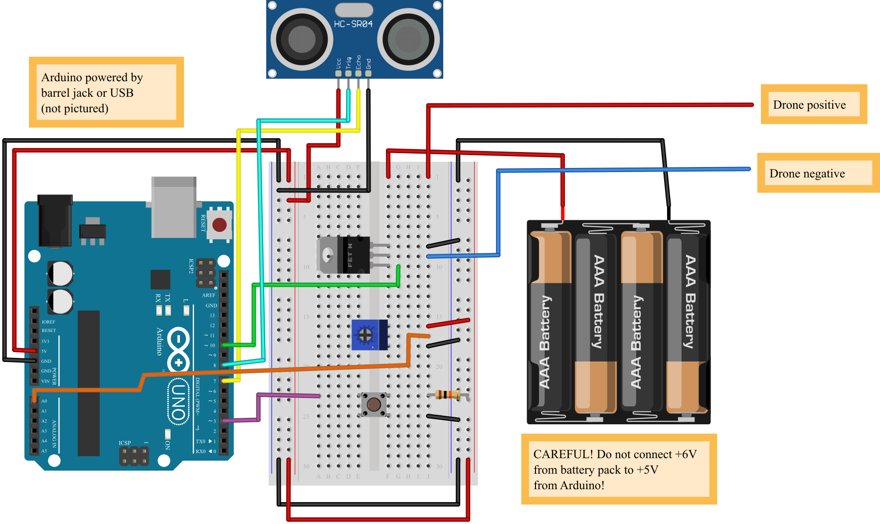
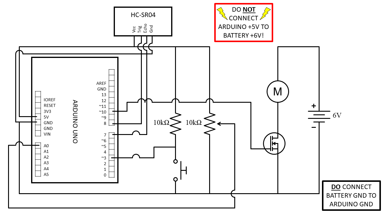
Can you design a PID controller for your drone that results in optimal behavior? You may need to do some of your own research about PID controllers to get started. The Bibliography contains several references that may be useful. Refer to DIY Mini Drone: Arduino™ Altitude Control for instructions to build your drone. The circuit diagram is reproduced in Figures 1 and 2, and you can download working code for a proportional controller here. (Click these links for a bigger version of the diagram and the circuit schematic.)
/-/https/www.sciencebuddies.org/cdn/Files/17050/15/drone-arduino-altitude-breadboard-circuit-1.png)
Figure 1. Breadboard diagram for Arduino drone controller.
/-/https/www.sciencebuddies.org/cdn/Files/17051/17/arduino-drone-control-circuit-diagram-1.png)
Figure 2. Circuit schematic for Arduino drone controller.
Bibliography
- National Instruments. (2020, March 17). PID Theory Explained. Retrieved March 2, 2021.
- Wikipedia Contributors. (n.d.). PID Controller. Retrieved March 2, 2021.
- Cook, J. (2019, November 1). PID Controller Basics & Tutorial: PID Implementation in Arduino. Retrieved March 2, 2021.
Ask an Expert
Global Goals
The United Nations Sustainable Development Goals (UNSDGs) are a blueprint to achieve a better and more sustainable future for all.
/-/https/www.sciencebuddies.org/cdn/Files/19752/5/E-WEB-Goal-09.png)
Frequently Asked Questions (FAQ)
- Make sure your batteries are firmly inserted into the battery pack and facing the proper direction.
- Make sure the battery pack is on.
- Double-check all of your twisted wire connections. Loose connections can prevent the motors from spinning.
- Make sure that you can easily slide the drone up and down the dowels by hand. If you let go of the drone after lifting it, it should fall back to the bottom. If the drone gets stuck:
- Make sure the wooden dowels are parallel and the spacing between them is even. If the dowels are crooked, this will cause the drone to get stuck.
- Make sure the two straws that act as guide for the drone are parallel and aligned with the dowels. If the straws are crooked, this can cause the drone to get stuck even if the dowels are parallel.
- Make sure that all four propellers are properly mounted and spinning in the right direction. If you turn the drone on and hold your hand under each propeller, you should feel air blowing down on your hand. If you hold your hand over a propeller and you feel air blowing up, then you either a) have the wires for that motor reversed or b) mixed up the clockwise and counter-clockwise propellers. Revisit the procedure to make sure you have all four motors wired correctly with the correct propeller mounted on each motor.
- Do not use excessive amounts of glue or tape when building your drone. If the drone is too heavy, it will not lift off, even if everything else is built correctly.
- Make sure the wires from the battery pack are free and not getting snagged on anything.
- Make sure the motors are all pointed straight up. This will give your drone maximum lift. If the motors are tilted at an angle, the drone will not have as much lift.
- Just like any other battery-operated device, your drone's batteries will wear out eventually. If your drone seems sluggish or is no longer lifting off, replace the batteries. Note: some off-brand batteries cannot provide enough power for the drone to lift off. We recommend using name-brand batteries.
- Check if the drone has become damaged from repeated use or if your wooden dowels have become misaligned.
Careers
If you like this project, you might enjoy exploring these related careers:
/-/https/careerdiscovery.sciencebuddies.org/cdn/Files/1725/18/4161_Michelle_Easter_and_Curiousity_Clone.jpg)
/-/https/careerdiscovery.sciencebuddies.org/cdn/Files/835/18/msfc-202000343.jpg)
/-/https/careerdiscovery.sciencebuddies.org/cdn/Files/1450/21/iStock-1227179796.jpg)
/-/https/careerdiscovery.sciencebuddies.org/cdn/Files/1223/17/iStock-971549326.jpg)

/-/https/img.youtube.com/vi/SH3M1WZs7FM/0.jpg)
/-/https/img.youtube.com/vi/SD6LToUppRk/0.jpg)
/-/https/img.youtube.com/vi/jjgXGTaKTxE/0.jpg)