Abstract
HELP! Locating survivors trapped under rubble is a difficult and dangerous task. After a natural disaster, like an earthquake, rescuers must act quickly to save as many lives as possible. They can use robots with different types of sensors to help find survivors. In this project you will build a sound-tracking robot that can use two microphones to drive toward a sound source. Designing the robot's algorithm will be up to you.
Summary
Previous experience with Arduino is recommended. See our How to Use an Arduino page.
Bluebot 4-in-1 robotics kit and Electronics Kit for Arduino are available from our partner Home Science Tools®. See the Materials section for details.
No issues
/-/https/i.ytimg.com/vi/AUguvwpnJ5M/maxresdefault.jpg)
Objective
Build a sound-tracking robot and write a program to make it drive toward a sound source.
Introduction
Robots can go places that are dangerous for humans, like damaged buildings that are at risk of collapse or areas contaminated by radiation or severe pollution. This makes robots useful in search and rescue situations, especially after natural disasters like earthquakes, hurricanes, and landslides. Robots like the one in Figure 1 can work alongside human rescue crews to help find survivors.
/-/https/www.sciencebuddies.org/cdn/Files/19573/10/search-and-rescue-robot.jpg)
Figure 1. A robot at an indoor competition designed to simulate finding survivors after an earthquake.
Just as humans use different senses, like sight, sound, and touch, robots can use many types of electronic sensors to gather information from their environment. They can use cameras and computer vision to recognize objects. But what about environments where it is difficult to see, like the rubble of a collapsed building after an earthquake? A robot might have to rely on another type of sensor to locate people trapped under the rubble—like a microphone to listen for the sound of a person calling for help.
Most humans can naturally use their two ears to tell which direction a sound is coming from. This is called binaural hearing. A robot can do the same thing by recording sound in stereo using two microphones. This works because sound waves travel radially outward from the sound source. As the waves expand outward, they get quieter. This means that the sound will seem louder to the microphone closer to the sound source, as shown in Figure 2. The sound will also reach that microphone slightly before it reaches the farther microphone.
/-/https/www.sciencebuddies.org/cdn/Files/19574/10/stereo-microphones-sound-wave.png)
A dot in the top right corner of the image is the sound source. Sound waves, represented by quarter-arcs, radiate out from the source toward the bottom left of the image. Two microphones are placed just to the left and right of the center of the image. Microphone #1 is on the left and microphone #2 is on the right.
Figure 2. A sound wave expands radially outward from a source toward two microphones. The sound wave will reach microphone #2 first and will seem louder to microphone #2 than to microphone #1.
While they are represented by lines in Figure 2, sound waves are actually traveling pressure waves. Air pressure fluctuates above and below the baseline atmospheric pressure as air particles bump into each other (Figure 3). Larger amplitude fluctuations in pressure result in louder sound, and higher frequency fluctuations result in higher-pitched sound. Microphones convert this changing air pressure into an electrical voltage, which can be read by a microcontroller like an Arduino.
/-/https/www.sciencebuddies.org/cdn/Files/19575/10/sound-wave-pressure-graph.png)
The first segment of the line showing pressure is horizontal at a y value of zero, representing the baseline atmospheric pressure. Farther to the right, the line moves up and down, showing the fluctuation above and below the baseline pressure. The amplitude of the wave is the vertical distance from the baseline to a peak or trough.
Figure 3. Graph showing an example sound wave. The x axis of the graph is time, and the y axis is pressure (which can be measured either as absolute pressure or as a change from baseline atmospheric pressure). Section 1 represents a period of silence and section 2 represents a period of sound. The arrow labeled 3 represents the baseline atmospheric pressure, and the arrow labeled 4 shows the amplitude of the wave (the change from atmospheric pressure). The graph of a microphone's output would look the same, but the y-axis would be voltage instead of pressure. (Image credit: Wikimedia Commons user CLI, CC BY-SA 4.0)
There are different ways to process the sound recorded by multiple microphones in order to determine the direction of the source. One method is to compare the amplitudes of the two sound waves and assume that the louder wave was detected by the microphone closer to the source. If you can record data fast enough, you can also check to see which microphone recorded a sound earlier, as shown in Figure 4.
/-/https/www.sciencebuddies.org/cdn/Files/19576/10/stereo-car-sound.png)
Figure 4. Sound recorded by a stereo microphone as a car drove by, showing the time difference between left and right. The x axis of the graph is time and the y axis is voltage. (Image credit Wikimedia commons user Sophie means wisdom, CC BY-SA 3.0)
In this project you will use the first method. You will mount two microphones on an Arduino robot, use them to record sound, and compare the resulting measurements to find the one with the greater amplitudes. We will provide example code and a circuit diagram to get you started, but it is up to you to decide what to do with this information. When should your robot decide to turn and drive toward a sound? When should it drive straight? When should it consider the sound "noise" and just ignore it? You will design and code your own algorithm to control the robot's behavior. Before you get started, you may wish to watch this video to learn more about the microphones you will use in this project:
/-/https/i.ytimg.com/vi/bMs5J4bJOD0/maxresdefault.jpg)
Terms and Concepts
- Search and rescue
- Sensor
- Microphone
- Binaural
- Stereo
- Air pressure
- Amplitude
- Frequency
- Voltage
Questions
- What are some uses for search and rescue robots?
- How does binaural hearing let humans determine the direction of a sound source?
- How can robots use stereo microphones to determine the direction of a sound source?
Bibliography
- Science Buddies Staff (n.d.). How to Use an Arduino. Retrieved March 20, 2023.
- Arduino (n.d.). Language Reference. Retrieved July 6, 2020.
- Texas Instruments (2016 January). L293x Quadruple Half-H Drivers. Retrieved July 8, 2020.
- Henderson, T. (n.d.). Sound Waves and Music. The Physics Classroom. Retrieved March 20, 2023.
- Science Buddies Staff (n.d.). The Engineering Design Process. Retrieved March 20, 2023.
Materials and Equipment 
Recommended Project Supplies
/-/https/www.sciencebuddies.org/cdn/Files/9118/11/bluebot-motion-activated-googly-1100_1.png)
Materials for this project:
- BlueBot 4-in-1 Robotics Kit, available from our partner Home Science Tools®. The kit includes a robot chassis, wheels, motors, breadboard, batteries, and circuit parts to build four different robots.
-
Electronics Kit for Arduino, available from our partner Home Science Tools®.
- Note: This project will work with the Arduino UNO R3, UNO R4 Minima, UNO R4 WiFi, and compatible third-party boards.
- Windows or Mac computer. See this page if you have a Chromebook. Your computer will need:
- Access to the Arduino IDE, either installed local version or web-based editor (note that Chromebooks can only use the web version). Watch this video for a comparison of the two options.
- USB port. The Science Buddies kit comes with a USB-A to B cable. The "B" end plugs into the Arduino and the "A" end plugs into your computer. You will need an adapter or different cable if your computer only has USB-C ports. Watch this video to learn about the different types of cables and adapters.
- Electret microphone with amplifier (2, not included in kit). These are available from various vendors. Most require soldering to attach the pins, so you will need access to a soldering iron. Examples: Adafruit, SparkFun, Amazon
- Some additional tools are recommended for working with circuits:
- A digital multimeter is strongly recommended for help with troubleshooting
- Alligator clip leads make it easier to connect your multimeter probes to your circuit
- Needle nose pliers or tweezers make it easier to handle small parts
- Wire strippers allow you to cut wires to custom lengths, keeping your circuit neater
- Double-sided foam tape
- Lab notebook
You may wish to purchase additional parts to customize or add features to your robot. See Variations section for ideas.
Disclaimer: Science Buddies participates in affiliate programs with Home Science Tools®, Amazon.com, Carolina Biological, and Jameco Electronics. Proceeds from the affiliate programs help support Science Buddies, a 501(c)(3) public charity, and keep our resources free for everyone. Our top priority is student learning. If you have any comments (positive or negative) related to purchases you've made for science projects from recommendations on our site, please let us know. Write to us at [email protected].
Experimental Procedure
- Follow the instructions in this video to assemble your Bluebot chassis. However, instead of mounting the 4xAA battery pack on top of the robot, mount it on the lower plate. Then mount your Arduino next to the breadboard on the top plate. This will make it easier to connect the circuit to the Arduino.
/-/https/i.ytimg.com/vi/SBeGl_IgWwY/maxresdefault.jpg)
- If needed, solder header pins to your microphone breakout boards.
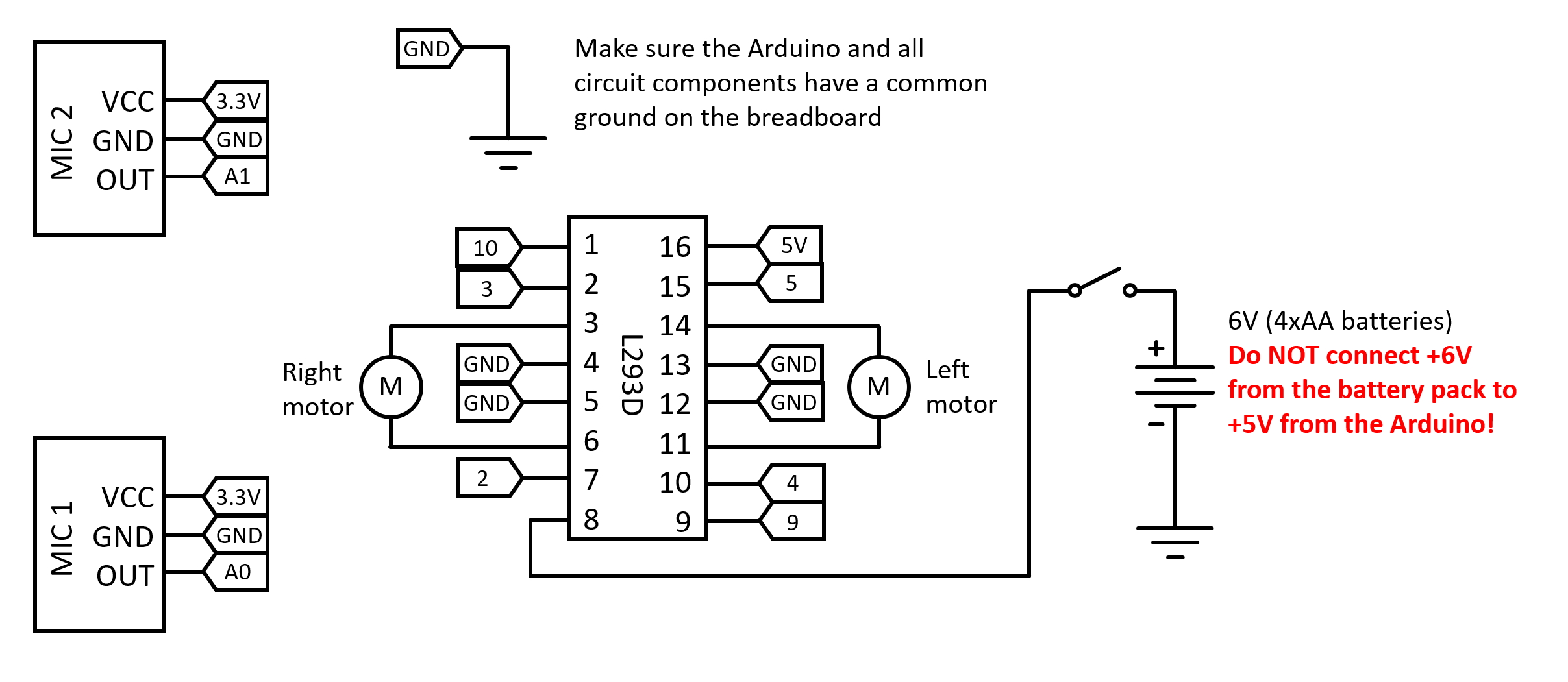
- Build the circuit shown in Figures 5 and 6. Be careful and note that there are three different power supplies involved in this circuit: 5 V and 3.3 V from the Arduino, and 6 V from the 4xAA battery pack. All parts of your circuit should have a common ground connection, but you must be careful not to short-circuit the different positive voltages to each other. Also note that the Arduino pins used in this diagram match the pins used in the example code, but you could choose to use different pins.
- Place the H-bridge in the breadboard, straddling the center gap. Refer to the H-bridge's datasheet from the Bibliography for the pinout. Going counterclockwise from the top left, starting with pin 1, connect the pins as follows:
- Pin 1 to Arduino pin 10
- Pin 2 to Arduino pin 3
- Pin 3 to the right motor negative wire
- Pin 4 to ground
- Pin 5 to ground
- Pin 6 to the right motor positive wire
- Pin 7 to Arduino pin 2
- Pin 8 to the 6 V from the AA battery pack
- Pin 9 to Arduino pin 9
- Pin 10 to Arduino pin 4
- Pin 11 to the left motor positive wire
- Pin 12 to ground
- Pin 13 to ground
- Pin 14 to the left motor negative wire
- Pin 15 to Arduino pin 5
- Pin 16 to 5 V from the Arduino
- Place a slide switch in the breadboard to use as an on/off switch for the 4xAA battery pack. Connect the battery pack's positive wire to the switch, and the negative wire to a ground bus.
- Connect your microphones using male-female jumper wires. Make sure you read the pin labels on your microphones, as they may be in a different order than the ones shown in the diagram.
- Microphone ground to Arduino ground
- Microphone VCC to Arduino 3.3 V (not 5 V). The documentation for the microphone recommends using the 3.3 V supply since it is less noisy than the 5 V supply.
- Each microphone out to one of the Arduino's analog inputs, such as A0 and A1.
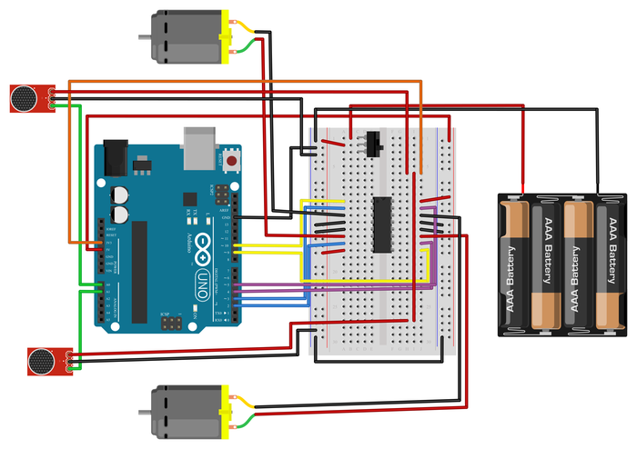
Figure 5. Breadboard diagram for the circuit. A larger version is available for download.

Figure 6. Schematic for the circuit. A larger version is available for download. - Place the H-bridge in the breadboard, straddling the center gap. Refer to the H-bridge's datasheet from the Bibliography for the pinout. Going counterclockwise from the top left, starting with pin 1, connect the pins as follows:
- Mount the microphones to your robot chassis. Experimenting with microphone placement and orientation is part of what you can try for this project. In general, you do not want the microphones too close together. Figure 7 shows one example, but you could put your microphones somewhere else, or even use other supplies (like popsicle sticks) to extend them.
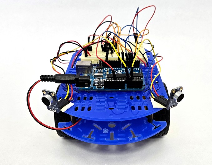
Figure 7. Microphones mounted on the robot chassis. - Download the example code. This code contains functions to make the robot drive and steer. It also samples the two microphones for a set period of time and calculates the maximum amplitude for each microphone. It does not, however, contain an algorithm that tells the robot what to do with this information—that part is your job! Make sure you read through all the comments and understand how the code works. If you do not know what an Arduino command does, you can look it up in the official Arduino language reference (see Bibliography).
- Plan out an algorithm for how your robot should react to the microphone readings. Your goal is to make the robot drive toward the source of a sound. Here are a few things to consider (this is not an exhaustive list):
- The robot's motors are pretty loud. Should you take readings while the robot is moving, or "stop and listen" so the motors' noise does not affect the readings? Can you calibrate the microphones to filter out (ignore) noise from the motors?
- There is probably some level of background noise in your environment. Do you want your robot to react to every single sound? Should you set a threshold so it only reacts if sound amplitude exceeds a certain volume? Do you want it to react to a person's voice, or something like a person clapping their hands?
- If a sound comes from in front of the robot, the two microphone readings will not be exactly the same. If the microphone readings are close, but not exactly equal to each other, you may want the robot to drive straight instead of turning.
- You can leave your robot plugged into the computer and use the serial print command to print out the values of different variables. This is useful for debugging and calibrating the microphones (e.g., measuring the amplitude produced by different sounds at different distances from the robot).
- Convert your algorithm to Arduino code. Make sure you document your code with comments so you understand what it does if you come back to it later.
- Upload and test your code. At first, it may be helpful to leave the robot's motors turned off (using the switch on the breadboard) and leave the Arduino connected to the computer with a USB cable. This will let you use the serial monitor to debug and observe the measured sound values. When you are ready, you can put the robot on the floor and let it drive around. You can leave the USB cable connected during testing, but it will pull on the Arduino and affect the robot's motion, so you will want to disconnect it eventually.
- Your robot may not work perfectly on the first try, and that is OK! Iteration is an important part of the engineering design process. Make observations about your robot's behavior. For example, does it ever turn in the wrong direction? Does it drive forward when it is not supposed to? Are there parameters you can tweak in your code to change these behaviors? What about changing the physical location of the microphones?
- Continue iterating until you can get your robot to reliably drive toward a sound source. See the Variations section for other ways to add to or improve your robot.
/-/https/www.sciencebuddies.org/cdn/Files/19579/10/microphones-mounted-chassis.jpg)
Ask an Expert
Global Goals
The United Nations Sustainable Development Goals (UNSDGs) are a blueprint to achieve a better and more sustainable future for all.
/-/https/www.sciencebuddies.org/cdn/Files/19754/5/E-WEB-Goal-11.png)
Variations
- You can connect up to six microphones to your robot since the Arduino UNO has six analog inputs. Can you place an array of microphones around your robot and use them to more accurately determine the direction of a sound source?
- The example code uses the digitalWrite command to drive the robot at full speed. Instead, you can use the analogWrite command for the H-bridge's enable pins (pins 1 and 9) to control the speed of each motor, as shown in our H-bridge tutorial video. Can you make your robot drive at variable speeds (for example, turn faster if a sound is detected farther to one side)? Note: The analogWrite command is also useful to fine-tune the robot to drive straight if it tends to drift off to one side.
- Can you add indicator LEDs to your robot? For example, you could have the robot turn on an LED when it is listening for a sound or use different LEDs to indicate when it is going to drive in different directions.
- Did you include threshold variables in your code? Can you add potentiometers to your circuit so you can adjust these thresholds without needing to edit the code?
- Is it possible to use an Arduino to determine the direction of a sound source using the timing of the sounds instead of the amplitude? Hint: You will need to look up the sampling rate of the Arduino's analog inputs and calculate how long it takes sound to travel between the microphones, based on the speed of sound and how far apart the microphones are.
- Can you add a voice recognition module to your robot to make it respond to voice commands?
- You can connect many other sensors to your robot, such as bump sensors, infrared sensors, light sensors, and ultrasonic sensors. Can you connect more sensors to help your robot navigate an environment with obstacles? In addition to search and rescue, can you think of other applications, like space exploration or autonomous cars?
Contact Us
Our kits are developed in partnership with Home Science Tools®. If you have purchased a kit for this project, Home Science Tools® is pleased to answer any questions.In your email, please follow these instructions:
- Include your Home Science Tools® order number.
- Please describe how you need help as thoroughly as possible:
Examples
Good Question I'm trying to do Experimental Procedure step #5, "Scrape the insulation from the wire. . ." How do I know when I've scraped enough?
Good Question I'm at Experimental Procedure step #7, "Move the magnet back and forth . . ." and the LED is not lighting up.
Bad Question I don't understand the instructions. Help!
Good Question I am purchasing my materials. Can I substitute a 1N34 diode for the 1N25 diode called for in the material list?
Bad Question Can I use a different part?
Contact Support

/-/https/img.youtube.com/vi/nCLHMmkFth8/0.jpg)
/-/https/img.youtube.com/vi/sGK1Q7jcEfY/0.jpg)
/-/https/img.youtube.com/vi/lLASgvqAddI/0.jpg)