Abstract
Plenty of animals, like dogs and horses, can walk and run on four legs, but what about robots? Sometimes legs are better than wheels—try out this project to design and build your own quadruped walking robot!
Summary
Previous Arduino experience is recommended. See our How to Use an Arduino page for tutorials.
A kit is available from our partner Home Science Tools®. See the Materials section for details.
No issues
/-/https/i.ytimg.com/vi/tCtgt-VoPUk/maxresdefault.jpg)
Objective
Design and build an Arduino robot that walks with four legs.
Introduction
Humans are pretty good at building vehicles with wheels, like cars. Wheels are great at going fast on flat surfaces like roads. Some vehicles can even drive off-road on fairly rough terrain. However, when it comes to things like going up stairs or getting over very uneven ground, sometimes legs are a better option. Thanks to millions of years of evolution, animals are great at getting around using legs. Humans are bipeds, meaning we walk in two legs. Many animals, like dogs and horses, are quadrupeds that walk on four legs. Insects are hexapods with six legs.
Building robots with legs that can walk, run, balance, and jump like animals can is a challenging task. Check out this robot called BigDog, made by a company called Boston Dynamics, that can walk on four legs and even recover from slipping on ice:
/-/https/i.ytimg.com/vi/cNZPRsrwumQ/maxresdefault.jpg)
In this engineering project, you will build your own (much smaller) quadruped robot using an Arduino and some craft supplies (Figure 1). The robot has four legs, each with two joints: one "hip" joint that rotates the whole leg forward and backward, and one "knee" joint that moves the lower part of the leg up and down. You will try to figure out the best gait, or order in which the robot moves its joints, to make it walk.
/-/https/www.sciencebuddies.org/cdn/Files/19834/10/arduino-walking-robot-front-view.jpg)
Figure 1. A quadruped robot with a cardboard box for a body and popsicle sticks for legs.
When designing your robot's gait, you will need to consider the location of the robot's center of mass and how this affects its stability. When a quadruped robot is walking and lifts one leg off the ground, the remaining three legs form a tripod. If the robot's center of mass is inside this tripod (when viewed from the top), the robot will be stable. However, if the center of mass is outside the tripod, the robot will start to fall over (Figure 2).
/-/https/www.sciencebuddies.org/cdn/Files/19839/10/quadruped-robot-stability.png)
Figure 2. Top-down view showing the stability of a quadruped robot. The front left leg (not pictured) is lifted off the ground. In the left diagram, the center of mass falls inside a stable tripod formed by the other three legs. In the right diagram, the center of mass falls outside the support tripod, so the robot is unstable.
To build the robot, you will need to know how to use servo motors with an Arduino. Each of the robot's joints is made from a single motor, so there are eight motors total (two for each leg). Watch this video to learn how to use a servo motor:
/-/https/i.ytimg.com/vi/qJC1nt_eJZs/maxresdefault.jpg)
Now, get ready to build your own walking robot!
Terms and Concepts
- Biped
- Quadruped
- Hexapod
- Gait
- Center of mass
- Stability
- Tripod
- Servo motor
Questions
- What are some advantages and disadvantages of using legs instead of wheels?
- How do animals' gaits change at different speeds? For example, think about how dogs walk, trot, and run. How many feet are on the ground at any one time?
- What are some recent developments in the world of walking robots? You will need to do your own up-to-date research to look at recent news articles or publications.
Bibliography
- Finio, B. (n.d.). How to Use an Arduino. Science Buddies. Retrieved August 29, 2023.
- Science Buddies Staff (n.d.). Engineering Design Process. Science Buddies. Retrieved August 29, 2023.
Materials and Equipment 
Recommended Project Supplies
/-/https/www.sciencebuddies.org/cdn/Files/19915/12/SB_ARDNSTR_web__01473.jpg)
Note: this is an engineering design project, so the following materials list is just a suggestion. You can substitute or add other materials.
-
Electronics Kit for Arduino, available from our partner Home Science Tools®.
- Note: This project will work with the Arduino UNO R3, UNO R4 Minima, UNO R4 WiFi, and compatible third-party boards.
- SG90 micro servo motors (8)
- Additional Jumper wires (shorter solid-core jumper wires are better for making connections on the breadboard)
- Male to male header pins
- 5V buck regulator (note: voltage regulators are also available on Amazon, but they may require soldering)
- 7.4V LiPo battery
- Compatible LiPo battery charger
- JST plug connector
- Windows or Mac computer. See this page if you have a Chromebook. Your computer will need:
- Access to the Arduino IDE, either installed local version or web-based editor (note that Chromebooks can only use the web version). Watch this video for a comparison of the two options.
- USB port. The Science Buddies kit comes with a USB-A to B cable. The "B" end plugs into the Arduino and the "A" end plugs into your computer. You will need an adapter or different cable if your computer only has USB-C ports. Watch this video to learn about the different types of cables and adapters.
- Small cardboard box
- Popsicle sticks
- Double-sided foam tape
- Zip ties
- Scissors
- Hot glue gun
- Lab notebook
Disclaimer: Science Buddies participates in affiliate programs with Home Science Tools®, Amazon.com, Carolina Biological, and Jameco Electronics. Proceeds from the affiliate programs help support Science Buddies, a 501(c)(3) public charity, and keep our resources free for everyone. Our top priority is student learning. If you have any comments (positive or negative) related to purchases you've made for science projects from recommendations on our site, please let us know. Write to us at [email protected].
Experimental Procedure
- Make a general sketch of how you plan to build your robot and where you will mount all the parts. Figures 3, 4, and 5 show top, bottom, and side views respectively of the Science Buddies robot. The Arduino and breadboard are mounted on the top of a cardboard box. The voltage regulator is mounted on the back of the box and the battery is taped under the box. The legs are made from popsicle sticks attached to the servo horns with double sided tape and zip ties (note: we later found that hot glue made sturdier connections). Remember that this is an engineering design project, so you can come up with your own design, you do not have to copy the design shown here.
/-/https/www.sciencebuddies.org/cdn/Files/19845/10/walking-robot-top-view.jpg)
/-/https/www.sciencebuddies.org/cdn/Files/19842/10/walking-robot-bottom-view.jpg)
/-/https/www.sciencebuddies.org/cdn/Files/19844/10/walking-robot-side-view.jpg)
Figure 5. Side view of the robot.
- Arduino tutorials that show you how to use a single servo motor usually power the servo directly from 5 V on the Arduino. This works because the small servos are rated for 4.8–6 V, and the Arduino can provide enough current for a single servo. However, the Arduino's 5 V pin cannot provide enough current to drive all eight servo motors at once. We recommend powering your Arduino and motors using the circuit shown in Figure 6.
- The Arduino is powered by the 7.4 V LiPo battery through its Vin pin, where it can accept between 7–12 V as an input.
- Since 7.4 V is too high to power the servos directly, this voltage is also sent through a voltage regulator that converts it to 5 V. The voltage regulator has a much higher current rating than the Arduino. This allows you to safely power the motors without drawing too much current through the Arduino.
- You can learn more about powering Arduino projects from our Powering Your Arduino Project video and the official Powering Alternatives for Arduino Boards page.
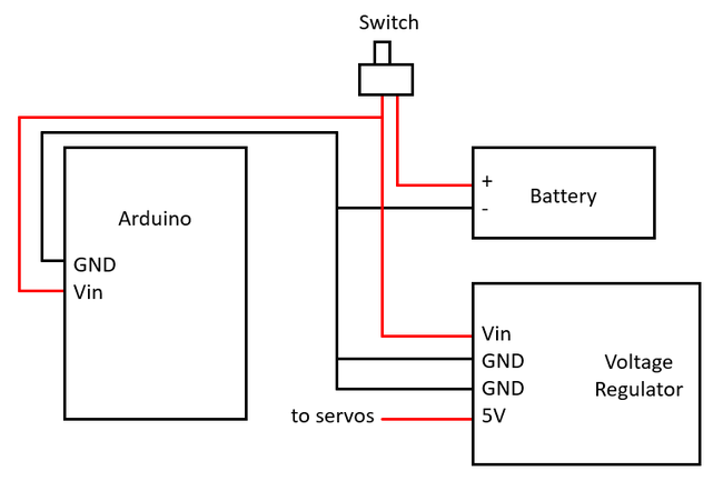
Figure 6. Circuit diagram for powering the robot. The positive wire from the 7.4 V battery goes to a switch. The other side of the switch goes to the Arduino Vin pin and the input voltage of the voltage regulator. The 5 V output from the regulator goes to the positive wire of each servo motor. All components in the circuit must have a common ground, but be careful not to short-circuit the different positive voltages together (including the 5 V output from the regulator and the 5 V pin on the Arduino). - Connect the eight servo motors to your Arduino as shown in Figure 7.
- Each servo motor has three connections: ground (brown), power (red), and signal (orange). Note that if you purchased different servo motors than the ones in the materials list, the colors may be different.
- Break off the male-male header pins in sets of three and use them to connect the female ends of the servo motor cables to the breadboard, then use additional jumper wires to make connections to the Arduino.
- Make sure you connect the power wires to the 5 V supply from the voltage regulator and not the 5 V supply from the Arduino.
- Make sure you keep track of which motor is connected to which Arduino pin. You may wish to label the motors with a permanent marker.
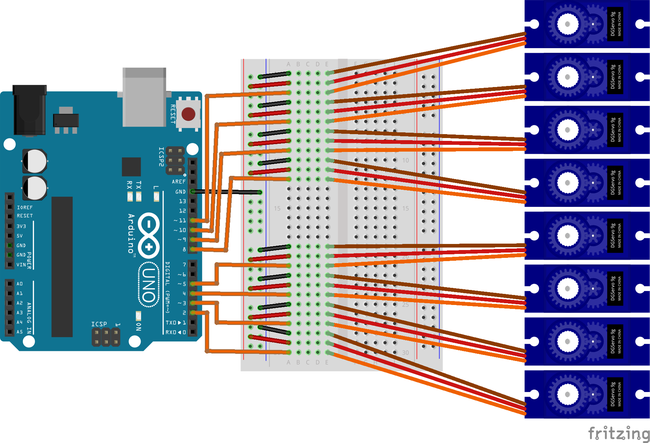
Figure 7. Breadboard diagram for connecting the eight servos to the Arduino (battery and voltage regulator not pictured, the servos should be powered by the 5 V output from the voltage regulator). - Test your circuit to make sure all eight servos work properly. It will be easier to troubleshoot any issues now before you have assembled the robot. You can use the servo test example code to test your servos. This code will move the servos attached to each pin one at a time. It will be easier to see the servos move if you attach servo horns before running the code.
- Once you are sure your circuit is working, it is time to assemble your robot. Use double-sided foam tape, hot glue, and zip ties for the attachments as needed. You may need to unplug some wires and re-connect them later in order to build the robot. Refer to figures 3, 4, and 5 for guidance, but remember that this is an engineering design project, so you can come up with your own design. Figure 8 shows the motor configuration for our robot and the direction of positive rotation for each motor (e.g. increasing leg 1's angle will cause it to rotate forward, increasing knee 1's angle will cause it to rotate outward), but your configuration may be different depending on how you attach the motors.
- Mount the Arduino, breadboard, voltage regulator, and battery to the cardboard box.
- Attach the four "hip" motors to the underside of the box. Use additional pieces of cardboard as supports to stiffen the motors if needed.
- Use popsicle sticks to form the upper parts of the legs.
- Attach the "knee" motors to the legs.
- Use popsicle sticks to form the lower parts of the legs.
- Add something (like a dab of hot glue) to the robot's "feet" to give them a better grip on slippery surfaces like wood.
- As needed, carefully re-route all wires to the breadboard. You may want to poke holes in the box to route wires through or use zip ties for cable management. Make sure the wires will not get tangled in the robot's legs when they move.
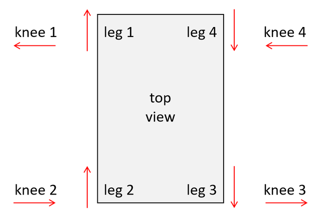
top view of the robot with the front of the robot facing the top of the image. Top left corner: leg 1, positive rotation forward, knee 1, positive rotation outward. Bottom left corner: leg 2: positive rotation forward, knee 2, positive rotation inward. Bottom right corner: leg 3, positive rotation backward, knee 3, positive rotation outward. Top right corner: leg 4, positive rotation backward, knee 4, positive rotation inward.
Figure 8. The robot's joint configuration and direction of positive rotation for each motor. - Now for the challenging part: programming your robot to walk! You will need to write a program to control your robot's gait by moving the legs. You can use our quadruped robot example code to start, but since every robot is different, this code may not work for your robot. Here are some things to consider:
- You will have to decide in what order you will move joints. For example, you could lift knee 1, swing leg 1 forward, then put knee 1 down, repeat this process for the other three legs, then swing all four legs backward at once. Alternatively, you could swing the legs backward one at a time or in pairs.
- Remember to think about the robot's center of mass and forming a stable support tripod with the legs.
- Think about the range of motion you need for each joint. You probably do not need each motor to rotate through its full 180 degree range.
- Watch your robot to see if it sags under its own weight. Try to think of ways you can reinforce the robot to make it sturdier, or how you can make it lighter. As noted above, we found that hot glue worked better than double-sided tape for sturdy connections.
- Make good use of variables and functions to keep your code organized. For example, you can use variables to control servo angles instead of hard-coding certain angles, and you can write functions to control different leg movements such as "leg 1 forward."
- Using a single servo "write" command with a large change in angle can result in very jerky motion. Instead, you can use while loops with smaller, incremental changes in angle to result in smoother motion. See the Arduino 'sweep' page for example code.
- It may take a lot of experimentation on your part to find a gait that makes your robot move forward. Your robot might fall over or even move in circles at first, but that is OK! Iteration is an important part of the engineering design process. Keep trying and see if you can get your robot to move forward, even if it moves slowly or awkwardly.
- If you have a lot of trouble getting your quadruped robot to walk, consider adding two more legs to make a hexapod. This makes it easier to form a stable support tripod and keep the robot from falling over. See the Variations section for some more suggestions.
/-/https/www.sciencebuddies.org/cdn/Files/19841/10/arduino-walking-robot-power-circuit.png)
/-/https/www.sciencebuddies.org/cdn/Files/19840/10/arduino-eight-servos.png)
/-/https/www.sciencebuddies.org/cdn/Files/19843/10/walking-robot-joints-top-view.png)
Ask an Expert
Global Goals
The United Nations Sustainable Development Goals (UNSDGs) are a blueprint to achieve a better and more sustainable future for all.
/-/https/www.sciencebuddies.org/cdn/Files/19752/5/E-WEB-Goal-09.png)
Variations
- Can you find more than one gait that makes your robot walk? Can you compare different gaits to see which is faster?
- Can you build a bipedal robot that walks on two legs like a human?
- Can you build a hexapod insect robot that walks on six legs? Try programming the robot to walk with an "alternating tripod" gait, where three legs (the front and back legs on one side, and the center leg on the opposite side) are always on the ground at any given time. This can help keep the robot stable. There are many examples of Arduino hexapod robots online.
- Can you use laser-cut or 3D-printed parts to make a sturdier robot?
- Can you use larger, more powerful servos to better support the robot's weight?
- Can you build a robot that can walk over obstacles or uneven ground?
- Can you build a robot that walks using only mechanical timing and no Arduino? Check out our Build a Simple Walking Robot project.
Careers
If you like this project, you might enjoy exploring these related careers:
/-/https/careerdiscovery.sciencebuddies.org/cdn/Files/1725/18/4161_Michelle_Easter_and_Curiousity_Clone.jpg)
/-/https/careerdiscovery.sciencebuddies.org/cdn/Files/1731/17/iStock-1187291213.jpg)
/-/https/careerdiscovery.sciencebuddies.org/cdn/Files/1223/17/iStock-971549326.jpg)
/-/https/careerdiscovery.sciencebuddies.org/cdn/Files/1450/21/iStock-1227179796.jpg)
Contact Us
Our kits are developed in partnership with Home Science Tools®. If you have purchased a kit for this project, Home Science Tools® is pleased to answer any questions.In your email, please follow these instructions:
- Include your Home Science Tools® order number.
- Please describe how you need help as thoroughly as possible:
Examples
Good Question I'm trying to do Experimental Procedure step #5, "Scrape the insulation from the wire. . ." How do I know when I've scraped enough?
Good Question I'm at Experimental Procedure step #7, "Move the magnet back and forth . . ." and the LED is not lighting up.
Bad Question I don't understand the instructions. Help!
Good Question I am purchasing my materials. Can I substitute a 1N34 diode for the 1N25 diode called for in the material list?
Bad Question Can I use a different part?
Contact Support

/-/https/img.youtube.com/vi/9G3TaquPqDE/0.jpg)
/-/https/img.youtube.com/vi/uvp3hcEK3lU/0.jpg)
/-/https/img.youtube.com/vi/G7gvJEKh_p8/0.jpg)