LED Dance Glove: Get the Party Started with Your Own Interactive Light Show
Abstract
Have you ever seen clothing with built-in lights? This might sound like something out of a science-fiction movie, but electronic textiles (>e-textiles for short, also called wearable electronics or sewable circuits) really exist. Instead of using hard surfaces for circuits (like what goes inside your computer or cell phone), e-textiles weave electrical parts like batteries, wires, and lights directly into clothing that you can wear to make the clothing do fun, interesting things like light up, respond to sound, or even serve medical purposes (like a shirt that monitors heart rate and breathing patterns). In this science project, you will build a light-up "dance glove" that you can use to put on your very own light show!Summary
Ben Finio, PhD, Science Buddies
- SparkFun® is a registered trademark of SparkFun Electronics.
- Nintendo Entertainment System®, Super Nintendo Entertainment System®, and Nintendo 64® are registered trademarks of Nintendo.
Objective
Design and build an LED glove.Introduction
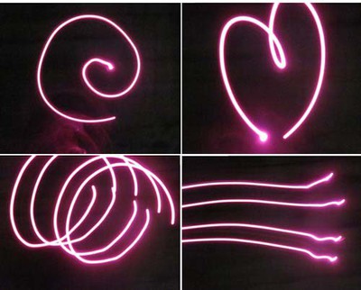
Clothing that lights up might sound like something out of a science-fiction movie, but electronic textiles (or e-textiles for short), are actually used in the real world for both decorative and practical purposes. Clothing with built-in lights (also called "wearable electronics") can be used in light shows and artistic or dance performances. For example, all of the photos in Figure 1 were taken in a dark room by waving a glove with built-in lights in front of a camera. Since the room is so dark, the camera takes a longer time to take the picture, letting in more light; this lets you "draw" shapes in midair using the glove! While the pictures in Figure 1 are pretty amateur, there is actually an International Gloving Championship, a competition where people "dance" using their hands with LED gloves. Do you think you can make gloves that are good enough to win a competition?

Figure 1. These pictures were all taken in a dark room using a glove, made by following the Procedure in this project, with built-in lights.
Once you build your own LED dance glove, you can take pictures like the ones in Figure 1, make movies, and show them off to your friends. This science project will teach you how; but first, you will need to learn a little bit about electrical circuits.
Electricity is what powers many of the devices that we use every day, like computers, TVs, lights, and phones. You can read more about electricity in the Science Buddies Electricity, Magnetism, & Electromagnetism Tutorial. Materials that let electricity flow easily are called conductors. Conductors are usually metals like copper, aluminum, or steel. Materials that prevent electricity from flowing are called insulators. There are many types of insulators, including most rubbers and plastics. Conductors, insulators, and other special components that you will learn about later are combined to make up electrical circuits, which allow electricity to flow through these components in a careful, controlled way, usually to power something like a light or a motor, or to do calculations inside a computer. Most electronic devices that you use every day have specialized circuits inside them. In this science project, you will build your own circuit to light up a glove that you can wear.
The circuit you will build in this science project can be represented by a circuit diagram. Circuit diagrams are the "language" that engineers and electricians use to represent physical circuits with drawings. They use symbols to represent physical objects. Figure 2 shows three different representations of the same simple example circuit: a photograph, a computer drawing, and a circuit diagram.
There are three circuit components shown in the circuit diagrams in Figure 1:
- Battery: The power supply for your circuit. Batteries have a positive terminal marked with a "+" sign, and a negative terminal (the symbol for negative is "-", but this is usually not marked on the battery).
- Light-emitting diodes (or LEDs for short): The lights in your circuit. LEDs have two wires sticking out of them, called leads (pronounced "leeds"), one positive and one negative. LEDs are like one-way valves for electricity; they only work when electricity flows through them in one direction.
- Resistors: Circuit components that resist the flow of electricity. They are important to use because they decrease the total amount of electricity flowing through a circuit, which is important because too much electricity flowing through an LED can cause it to burn out or break. Resistors also have two leads sticking out of them, but electricity can flow through them in either direction.
 Image Credit: Ben Finio, Science Buddies / Science Buddies
Figure 2. Three different representations of the same simple, example circuit with a battery, a resistor, and an LED. (Left) a photograph of the actual circuit in the real world. (Middle) a computer drawing of the same circuit. Each component is drawn to look like the object in the real world. (Right) the circuit diagram, which uses symbols to represent real-world objects. Notice how the symbols do not look exactly like the real-world object. This might seem confusing at first, but it is useful because not all batteries (or resistors or LEDs) look the same. For example, "coin cell" batteries that go into wrist watches look very different from AAA batteries.
The circuit you will build in this science project is slightly more complicated than the one shown in Figure 1. To continue, you will need to understand a few more concepts: open and closed circuits, and series and parallel circuits.
In a closed circuit, there is a complete conductive path through which electricity can flow. In a simple circuit with an LED or lightbulb and a battery, this means that the lightbulb will light up. In an open circuit, the conductive path is broken somehow; for example, by a disconnected wire. This prevents electricity from flowing, so the lightbulb will not light up. A switch can be used to control whether a circuit is open or closed, allowing you to perform functions like turning lights on and off. Figure 3 shows simple open and closed circuits.
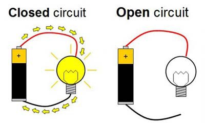 Image Credit: Ben Finio, Science Buddies / Science Buddies
Figure 3. In a closed circuit (left), there is a complete path from the positive to the negative terminal of the battery, so electricity can flow and the lightbulb will light up (the yellow arrows represent the flow of electricity). In an open circuit (right), one of the wires is disconnected, so the path is broken; this prevents electricity from flowing, so the lightbulb does not light up. Instead of disconnecting and reconnecting wires, a switch can be used to control whether a circuit is open or closed.
What if you want to hook up more than one light to a battery, like putting multiple LEDs onto a dance glove? There are two primary ways to do this: in series and in parallel. In a series circuit, all of the lights are connected to the battery in a single "loop," which means the electricity must flow through each light in order. In a parallel circuit, there are multiple "loops," so the current "splits up" and flows through each light individually. Figure 4 shows diagrams of series and parallel circuits. When using lightbulbs or LEDs, it is better to attach them in parallel; that way, even if one light goes out, the rest of them will stay on. So when you design your LED glove, it will be important to connect all your LEDs in parallel.
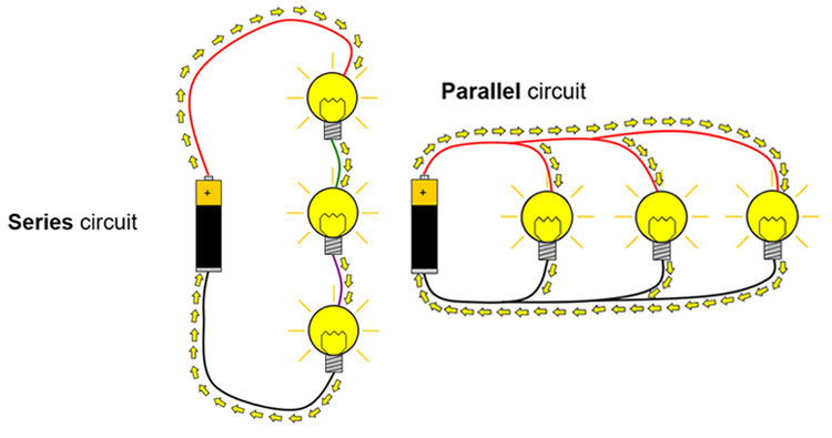 Image Credit: Ben Finio, Science Buddies / Science Buddies
Figure 4. In a series circuit (left), the electrical current (represented by yellow arrows) flows in a single loop. In a parallel circuit (right), the current flows in multiple loops.
So, now that you have a basic understanding of circuits, let us show you how to apply it when you build the LED dance glove. In this electronics science project, your goal is to build a wearable glove with a battery, multiple built-in LEDs, and an on/off switch. Figure 5 shows a circuit diagram for the circuit you will build.
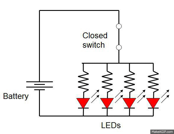 Image Credit: Ben Finio, Science Buddies / Science Buddies
Animated image shows two switches in a circuit being turned on and off to light two sets of LEDs. Each switch turns a set of four red and four green LEDs on and off and cycles through a combination of red LEDs lit, green LEDs lit, both LEDs lit, and no LEDs lit.
Figure 5. The circuit you will build in this electronics science project consists of a battery, a switch, and multiple LEDs with built-in resistors wired in parallel. The switch is used to control whether the circuit is closed or open, which turns the LEDs on or off.
And last but not least, in this science project you won't be designing a circuit that will go inside an electronic device like a computer; your circuit will go on a piece of clothing that you will wear! This means your design must be ergonomic. Ergonomics is the study of how devices and products comfortably fit the human body. For example, office chairs must be comfortable and ergonomic for people who sit in them for 8 hours a day. Consumer electronic devices like cell phones, MP3 players, and video game controllers must be ergonomic and fit easily into the human hand. As another example, can you see the design differences in three successive generations of Nintendo® video game controllers in Figure 6?
 Image Credit: Wikimedia Commons / Public domain
Figure 6. Three successive generations of video game controllers from (left) the original Nintendo Entertainment System® (NES), (middle) Super Nintendo Entertainment System® (SNES), and (right) Nintendo 64® (N64). Can you see how the products evolved to be more ergonomic and to fit the human hand better? (Wikimedia Commons user Evan-Amos, 2010)
Can you think of more examples of everyday products that were designed to be ergonomic? Use what you've learned to start thinking of important design criteria for your LED dance glove that involve ergonomics. Luckily, some products have already been designed with e-textiles in mind. For example, the LEDs and batteries in this science project were designed to be sewn directly into fabric, and you will use conductive thread instead of copper wires. This will make the job of designing an ergonomic glove a little easier. For a preview about the process of building the LED glove, watch this video before you move on to the Procedure section:
Terms and Concepts
- Electronic textiles or e-textiles
- Electricity
- Conductor
- Insulator
- Circuit
- Circuit diagram
- Symbol
- Battery
- Light-emitting diode or LED
- Resistor
- Closed circuit
- Open circuit
- Switch
- Series
- Parallel
- Ergonomic
Questions
- What is a circuit diagram, and how do its symbols represent real-world circuit components?
- Why is it important to also use a resistor when hooking up an LED to a battery?
- What is the difference between an open and a closed circuit? How can a switch be used to control whether a circuit is open or closed?
- Is it better to connect multiple LEDs in series or in parallel?
Bibliography
- Buechley, Leah. (n.d.). Build: turn signal biking jacket. MIT High-Low Tech Lab. Retrieved May 9, 2013.
- Wikipedia contributors. (2013, June 11). Human Factors and Ergonomics. Retrieved June 19, 2013.
- The Physics Classroom. (n.d.). Current Electricity - Chapter Outline. Retrieved June 19, 2013.
Materials and Equipment
Many of the supplies needed for this science project can be ordered from SparkFun Electronics.
- LilyPad LEDs (1 pack of 5); available from SparkFun Electronics in various colors. Note that these LEDs contain built-in resistors, so you do not need to purchase resistors separately.
- LilyPad coin-cell battery holder with built-in switch; available from SparkFun Electronics
- Alternatively, you can purchase a coin-cell battery holder and a power switch separately, but this will be more expensive.
- CR2032 coin-cell battery; available from SparkFun Electronics
- Sewing needle. A needle set is available from SparkFun Electronics or at local arts and crafts stores.
- Conductive thread (1 spool); available from SparkFun Electronics
You will also need to gather:
- Lab notebook
- Lightweight gardening or winter glove. We recommend using a fabric that can be sewn to easily, e.g. do not use heavy leather work gloves or thick, insulated winter gloves.
- Sewing thread (1 spool), color of your choice; available at local arts and crafts stores
- Fabric paint, color of your choice; available at local arts and crafts stores
- Optional: Digital camera to take pictures/videos of your LED dance glove performance.
- Someone who has experience with basic sewing
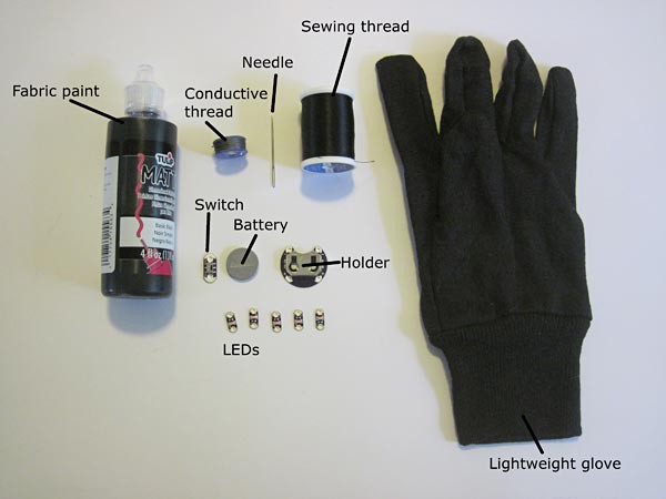 Image Credit: Ben Finio, Science Buddies / Science Buddies Image Credit: Ben Finio, Science Buddies / Science Buddies
|
| Figure 7. Materials required to make one LED dance glove. |
Disclaimer: Science Buddies participates in affiliate programs with Home Science Tools, Amazon.com, Carolina Biological, and Jameco Electronics. Proceeds from the affiliate programs help support Science Buddies, a 501(c)(3) public charity, and keep our resources free for everyone. Our top priority is student learning. If you have any comments (positive or negative) related to purchases you've made for science projects from recommendations on our site, please let us know. Write to us at scibuddy@sciencebuddies.org.
Experimental Procedure
- Design your LED dance glove.
- If you are not familiar with design projects, you can consult the Science Buddies Engineering Design Guide to help get you started.
- The following instructions will provide you with directions to build the LED dance glove from the video in the Introduction. Your task is to modify the design and adapt the instructions in order to create an LED glove that is perfect for you. For example, you may put your LEDs in different locations on the glove, or use different-colored LEDs. You will want to make sure the glove is ergonomic for you and easy for you to operate. Important: Remember that you need to wire your LEDs in parallel and not in series.
- Before you start building, you should make sketches of your design in your lab notebook, including both a circuit diagram and a drawing of how the circuit will actually look on the glove. Figure 8 shows a circuit diagram (it is a hand-drawn version of the same circuit shown in Figure 5) and Figure 9 shows a sketch of the glove.
- Important: Make sure that your design avoids short circuits. You should not cross threads over each other if one of them is connected to the positive side of the battery and one is connected to the negative side.
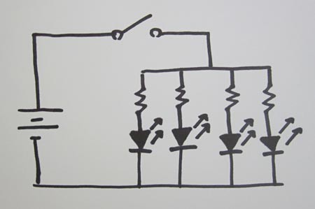 Image Credit: Ben Finio, Science Buddies / Science Buddies
Figure 8. A hand-drawn circuit diagram with a battery, switch, and four LEDs with resistors. This diagram is identical to Figure 5 from the Introduction; but remember that your diagram can be different (for example, if you want to use a different number of LEDs), although you should always wire your LEDs in parallel.
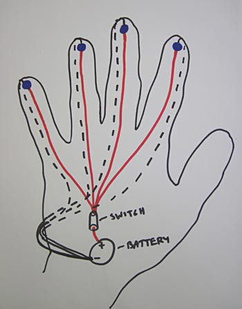 Image Credit: Ben Finio, Science Buddies / Science Buddies
Figure 9. A hand-drawn sketch of how the circuit components from Figure 8 will look when they are laid out on a left-hand glove. Red lines represent conductive thread coming from the positive battery terminal, and black lines represent conductive thread connected to the negative terminal. The "dashed" lines represent conductive thread on the underside of the glove. Blue dots on the fingertips represent the LEDs. Can you understand from this drawing that the LEDs are still arranged in parallel, even though it does not look exactly like the circuit diagram in Figure 8?
- Attach your circuit components to the glove using regular sewing thread.
- Follow the diagram you made in Step 1 to sew your LEDs and battery holder (and power switch if you purchased one separately) to your glove using regular sewing thread.
- Figure 10 shows four LEDs sewn to the fingertips of a glove, and the battery holder and switch sewn to the back.
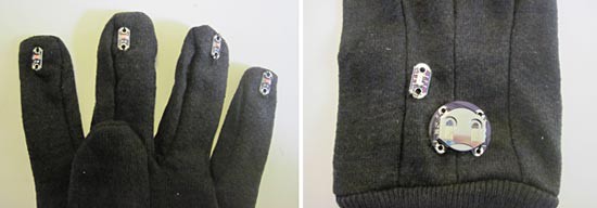 Image Credit: Ben Finio, Science Buddies / Science Buddies
Figure 10. (Left) Four LEDs sewn to the fingertips of the glove, (right) battery holder and power switch sewn to the back of the glove. Note: The image on the right shows a battery holder that is separate from its power switch, although you may use a battery holder with a built-in switch.
- "Wire" your circuit using conductive thread.
- Follow the diagram you made in Step 1 to sew electrical connections using the conductive thread.
- How exactly you do this will depend on the number of LEDs you are using, where you placed them, and whether you are using the battery holder with a built-in switch or a separate power switch.
- Remember that LEDs will only light up when current passes through them in the proper direction. Make sure that the positive terminals of your LEDs are connected to the positive side of the battery holder, both marked with a "+".
- Make sure the conductive thread is in good contact with the metal pads on each one of the boards for the LEDs, battery pack, and switch if applicable.
- Figure 11 shows complete wiring for the LED glove design in Figure 9.
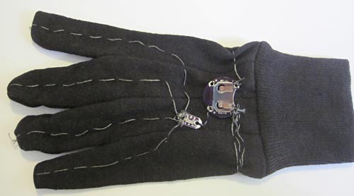 Image Credit: Ben Finio, Science Buddies / Science Buddies
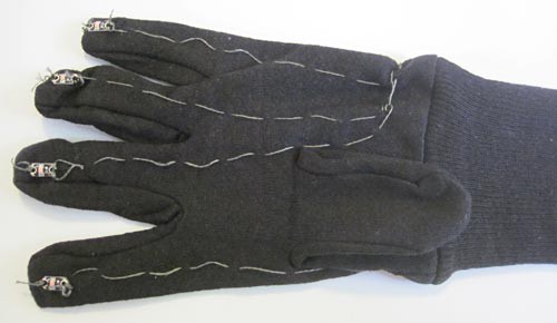 Image Credit: Ben Finio, Science Buddies / Science Buddies
Figure 11. (Top) Picture of the back of the glove, showing conductive thread that connects the positive battery terminal to the switch, and the switch to the positive terminal of each LED. (Bottom) Picture of the front of the glove. Conductive thread goes from the negative LED terminals back around the side of the glove to the negative terminal of the battery.
- Power-up your LED dance glove.
- Insert the coin-cell battery into the battery holder.
- Turn the power switch to "on."
- Your LEDs should light up, like in Figure 12.
- If one or more of your LEDs does not light up, double-check all of your conductive thread connections and make sure that they are not loose or broken. You can also try switching the orientation of the battery in the holder.
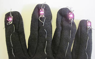 Image Credit: Ben Finio, Science Buddies / Science Buddies
Figure 12. After successfully wiring your glove with conductive thread, the LEDs should light up when you turn the power switch to "on."
- Insulate your conductive thread.
- Use fabric paint to cover the conductive thread on the outside of your LED dance glove.
- Let the fabric paint dry (read the label for instructions).
- Figure 13 shows the front and back of the LED dance glove after applying fabric paint for insulation.
- If possible, after the outside fabric paint dries, you can also turn your LED dance glove inside out and insulate the conductive thread on the inside. Only do this if you are confident you will not damage your circuit in the process (there is no shock hazard from the coin cell battery, so you do not need to worry if you cannot insulate the inside).
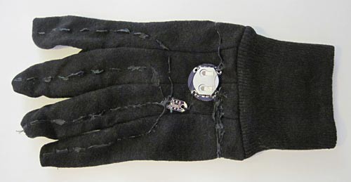 Image Credit: Ben Finio, Science Buddies / Science Buddies
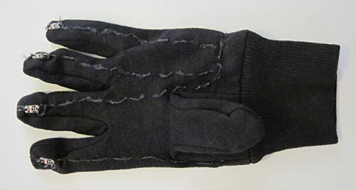 Image Credit: Ben Finio, Science Buddies / Science Buddies
Figure 13. The back (left) and front (right) of an LED dance glove after using fabric paint to insulate the conductive thread.
- Evaluate your LED dance glove design.
- How easy is it to turn your glove on and off?
- Are the LEDs placed in good positions to make designs with the glove?
- How would you rate the ergonomics of your glove?
- Have other people try your glove. Does it feel comfortable to them? What design improvements might you make?
- Feel free to adjust your design and try again! Engineers often build more than one version before they come up with their best product for market!
- Have fun! Try using a camera to take pictures like those in Figure 1 from the Introduction. You will need to take the pictures in a dark room, and it may help to have a friend hold the camera. You could even try making a "dance" video.
Ask an Expert
Variations
- Use multiple power switches to control different-colored LEDs on your gloves.
- What about making an LED glove that serves a different purpose? For example, check out the Science Buddies LED Traffic Glove Project Idea.
- Put LEDs on other items of clothing, such as hats or shirts.
- Use more than one battery to make your LEDs brighter. You may need to do research about connecting batteries in series and in parallel.
- If you are interested in a more advanced science project using a LilyPad Arduino, try these Project Ideas:
- Professional dance gloves used in "gloving" competitions include LEDs that blink or change color. Can you use a LilyPad Arduino to make a dance glove with blinking or color-changing LEDs? SparkFun carries an RGB LED specifically designed for the LilyPad, but you can also use regular RGB LEDs, which are much cheaper.
- Use a LilyPad Arduino and a microphone to make your LEDs respond to sound.
Careers
If you like this project, you might enjoy exploring these related careers:
Related Links
- Science Fair Project Guide
- Other Ideas Like This
- Electricity & Electronics Project Ideas
- Technology of Art Project Ideas
- My Favorites


