Abstract
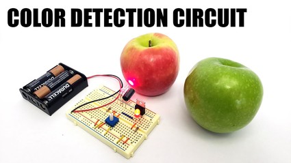
When you go to the supermarket, how do you pick out ripe fruits and vegetables? You might look at their size or color, or feel them for firmness. That might be easy to do when you pick out a half dozen apples, but imagine if you had to examine thousands of apples growing in a field, or strawberries coming down a conveyor belt getting ready for packaging. Suddenly, it is a lot harder to do yourself! What if a machine could pick and sort the produce for you? In this project, you will address part of the problem by building a circuit that can differentiate between two colors.Summary
Objective
Electronically measure how light is reflected from different color surfaces, and build a circuit that can differentiate between red and green produce.
Introduction
Many fruits and vegetables change color as they ripen. For example, tomatoes, strawberries, and red bell peppers all change from green to red. Color is just one way (along with size, texture, and smell) that you can tell if a fruit or vegetable is ready to be harvested or eaten. Imagine a factory that packs strawberries into plastic containers to be shipped off to grocery stores across the country. It might be useful to have a machine that automatically rejects any green strawberries that were picked before they were ripe. Or, you might want a machine on the farm that automatically recognizes strawberries by color and only picks the red ones to begin with. In this project you will build a circuit that uses visible light, which is the part of the electromagnetic spectrum our eyes can detect, to automatically differentiate between red and green objects.
Visible light comes in all the colors of the rainbow (which are measured by the wavelength of the light). Light can be reflected or absorbed by different surfaces (or transmitted through a transparent surface). The colors that we see in the world depend on what colors of light are reflected back to our eyes. White light (from the sun or most light bulbs) contains many different colors of light. When we look at a surface that is illuminated by white light, some colors are absorbed by the surface, and we see the color or colors that are bounced back. For example, an object that we see as red reflects mostly red light and absorbs the other colors (Figure 1, left). Objects that we see as white reflect all colors, and objects that we see as black absorb all colors. For a more detailed explanation of how humans perceive color, see the Bibliography.
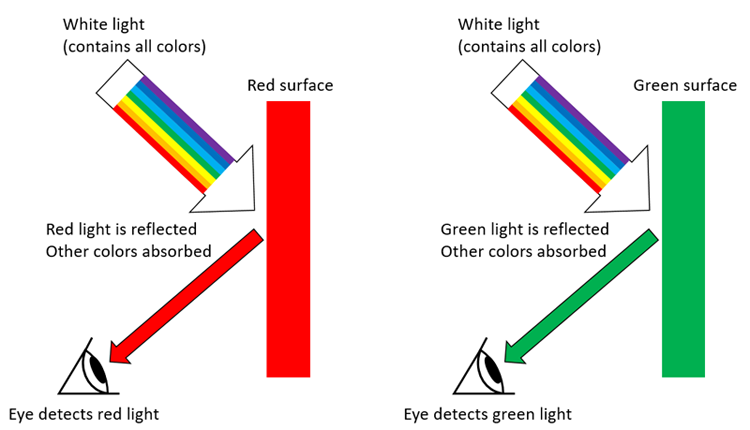 Image Credit: Ben Finio, Science Buddies / Science Buddies
Figure 1. When white light shines on a surface, some colors are absorbed, and other colors are reflected back to our eyes.
What happens if, instead of white light, you only shine a specific color of light on a surface? For example, if you shine a red light on a red surface, that red light will be reflected back. If you shine a red light on a green surface, however, the red light will be absorbed (Figure 2). If the green surface is only illuminated by red light, it will appear black.
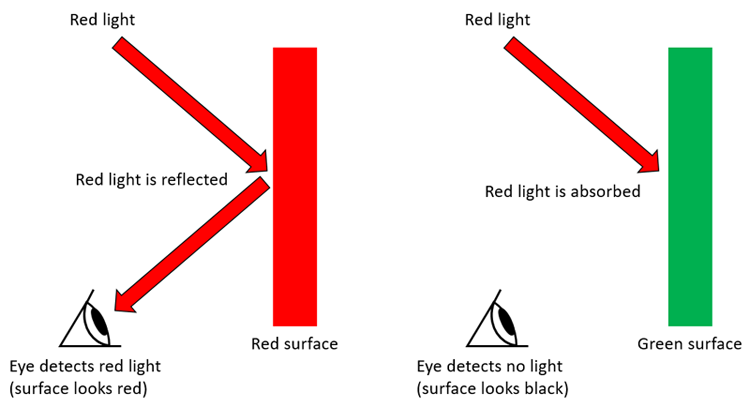 Image Credit: Ben Finio, Science Buddies / Science Buddies
Figure 2. Red light is reflected by a red surface and absorbed by a green surface.
You can use this information to build an electronic color-detecting circuit using a light-emitting diode (LED) and a photoresistor. An LED is a type of tiny light available in many different colors. A photoresistor is a special type of resistor. Resistors are electronic parts that resist the flow of electrical current (their resistance is measured in ohms [Ω]). A photoresistor's resistance depends on light—it has a high resistance in darkness and its resistance drops when exposed to light. When combined, a colored LED and a photoresistor can be used to differentiate between two different colors, as shown in Figure 3 (identifying any color requires multiple LEDs of different colors; see the variations section for more information). In this project, you will measure how a photoresistor's resistance changes when you illuminate different color surfaces with a red LED, and then use that information to build a circuit that can differentiate between red and green surfaces. Think of this as a first step toward building an automatic farming robot!
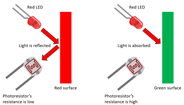 Image Credit: Ben Finio, Science Buddies / Science Buddies
Figure 3. Schematic of how an LED and photoresistor can be used to detect the color of a surface by measuring reflected light. (Photoresistor and LED images credit Fritzing.org)
Terms and Concepts
- Visible light
- Electromagnetic spectrum
- Wavelength
- Reflect
- Absorb
- Transmit
- Light emitting diode (LED)
- Photoresistor
- Resistor
- Resistance
- Ohms (Ω)
- Potentiometer
- Transistor
Questions
- What are some different ways you can tell when fruits or vegetables are ripe?
- What are some scenarios where it would be useful to have a machine tell if fruits or vegetables are ripe?
- Does the resistance of a photoresistor go up or down when more light is shined on it?
- If you shine a red light at a blue surface (similar to Figure 3), would the photoresistor's resistance be high or low?
Bibliography
- Henderson, T. (n.d.). The Electromagnetic and Visible Spectra. The Physics Classroom. Retrieved March 31, 2017.
- Resistorguide.com (n.d.). Photo resistor. Retrieved March 31, 2017.
- Estes, A. (2015, Feb 3). 13 Fascinating Farming Robots That Will Feed Humans of the Future. Gizmodo. Retrieved March 31, 2017.
- Finio, B. (2016, November 18). How to use a breadboard. Science Buddies. Retrieved March 31, 2017.
Advanced students who want to learn more about circuits should read these references:
- Taylor, C. (n.d.). Voltage, Current, Resistance, and Ohm's Law. SparkFun Electronics. Retrieved April 5, 2017.
- Lindblom, J. (n.d.). Voltage Dividers. SparkFun Electronics. Retrieved April 5, 2017.
- Lindblom, J. (n.d.). Transistors. SparkFun Electronics. Retrieved April 5, 2017.
- Lindblom, J. (n.d.). How to Read a Schematic. SparkFun Electronics. Retrieved April 5, 2017.
Materials and Equipment
- Assorted colored construction paper
- Corrugated cardboard
- Tape
- Small cardboard box or large textbook
- Red and green fruits or vegetables. If you have your own garden, you can grow your own and pick the fruits or vegetables at different times. Otherwise, you can go to a grocery store and purchase two different colors (for example, red and green tomatoes).
- The following electronic components, available from Jameco Electronics:
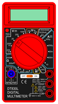
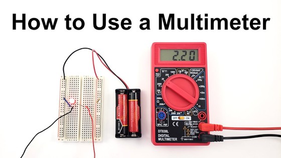
- Digital multimeter. See our multimeter tutorial if you do not know how to use a multimeter.
- Solderless breadboard, part # 20601
- Alligator clip leads (2 pack), part #2185483
- Jumper wire kit, such as part #2127718
- 3xAA battery holder, part #216136
- AA batteries (only 3 needed, but sold in multiples of 4), part #198707
- Super bright clear red LED (3), part #2188449. Only one is needed, but we recommend purchasing extras since LEDs can be burned out if connected incorrectly.
- N-channel MOSFET, part #2001373
- Photoresistor, part #202420
- 10 kΩ potentiometer, part #2118791
- Diffused red LED (only 1 needed, but sold in multiples of 10), part #333973
- 120 Ω resistor (only 2 needed, but sold in multiples of 10), resistor carbon film
- Lab notebook
Disclaimer: Science Buddies participates in affiliate programs with Home Science Tools, Amazon.com, Carolina Biological, and Jameco Electronics. Proceeds from the affiliate programs help support Science Buddies, a 501(c)(3) public charity, and keep our resources free for everyone. Our top priority is student learning. If you have any comments (positive or negative) related to purchases you've made for science projects from recommendations on our site, please let us know. Write to us at scibuddy@sciencebuddies.org.
Experimental Procedure
Build and Test Your Light-Measuring Circuit
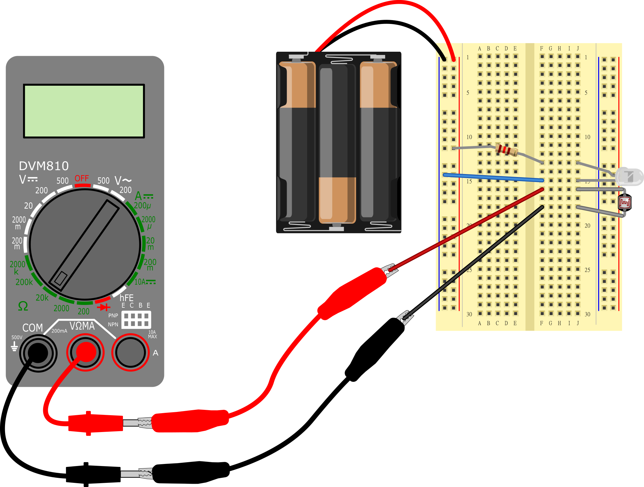
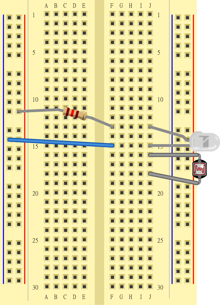
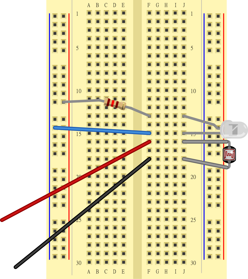
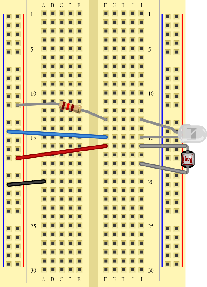
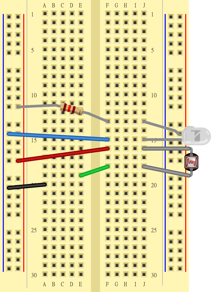
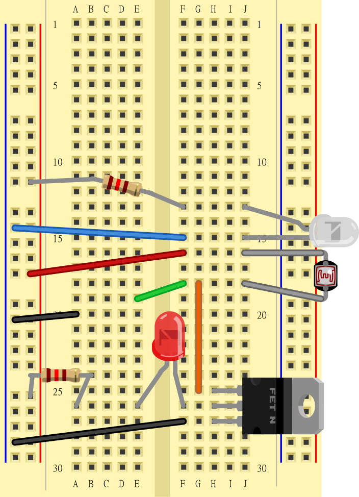
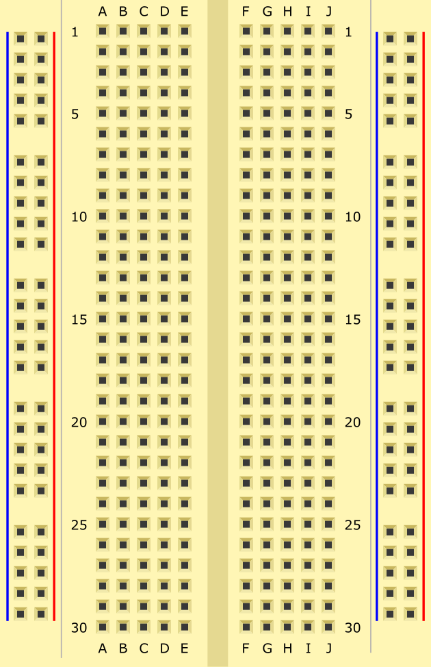
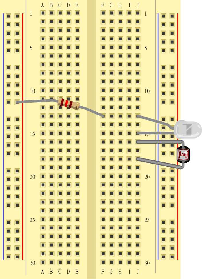
- Assemble the circuit on your breadboard as shown in the slideshow (make sure you read the captions!) and Table 1.
- If you have never used a breadboard before, watch the How to Use a Breadboard video before you start building your circuit.
- Note that your jumper wire kit will come with a variety of colors. You do not need to use colors that match the diagram.
- Always connect the battery pack last when building a circuit. If you see or smell smoke, or any part of your circuit feels hot, immediately disconnect the battery pack. This means you have a short circuit and need to double-check your wiring.


| Part | Picture | Notes |
|---|---|---|
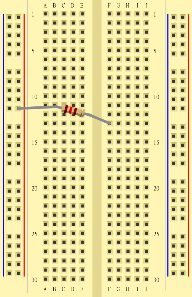
| 120 Ω resistor | (+) bus to F13 Direction does not matter |
|
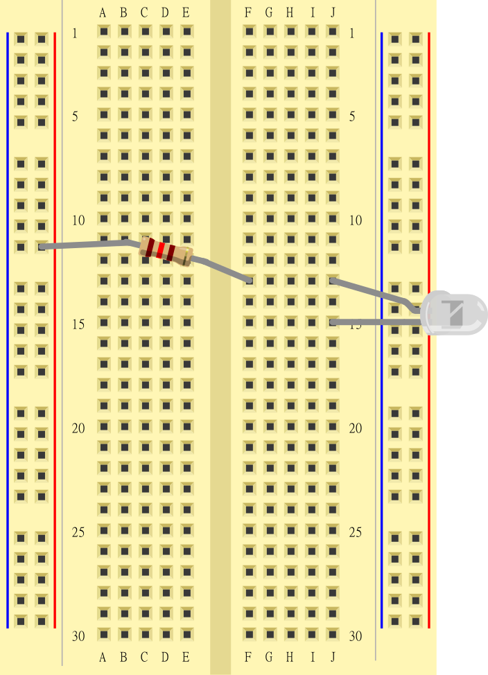
| Clear red LED | Long leg to J13 Short leg to J15 Direction matters, your LED will not light up if you get the two legs reversed! |
|
| Photoresistor | J16 to J18 Direction does not matter |
|
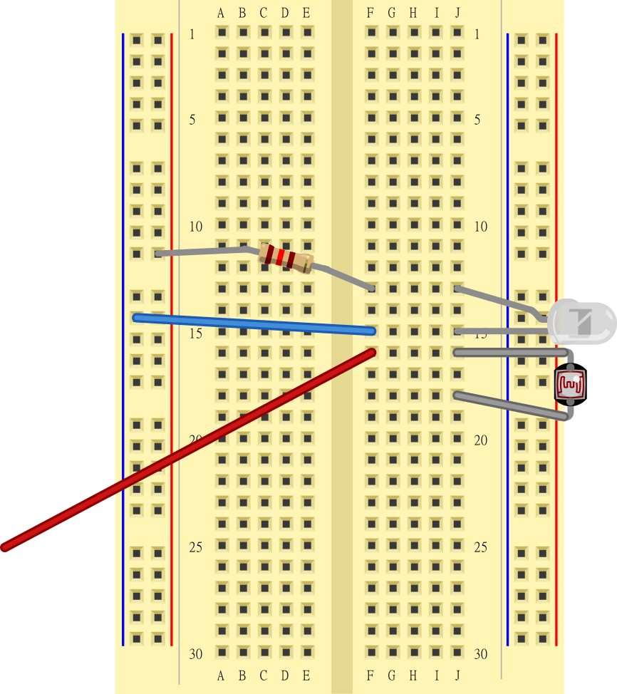
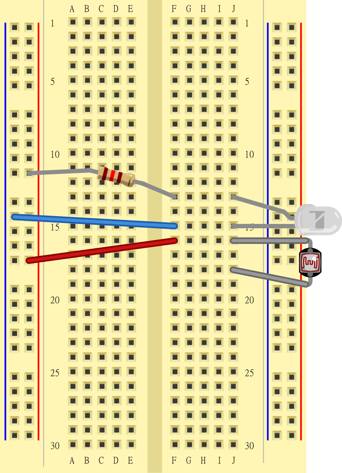
| Jumper wire | (-) bus to F15 Color does not matter |
|
| Jumper wire | One end to F16 Leave other end free Color does not matter |
|
| Jumper wire | One end to F18 Leave other end free Color does not matter |
|
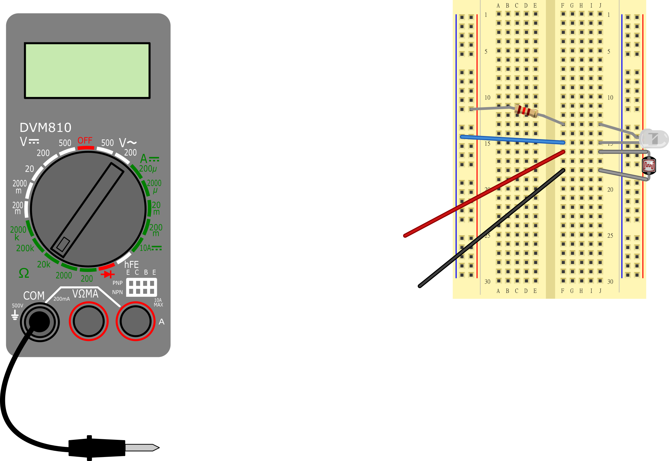
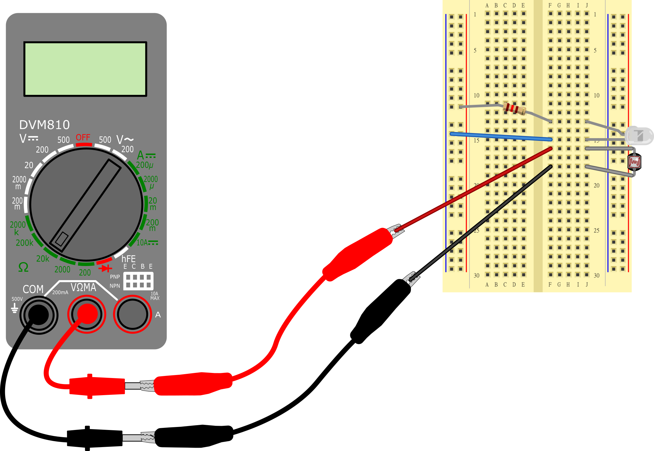
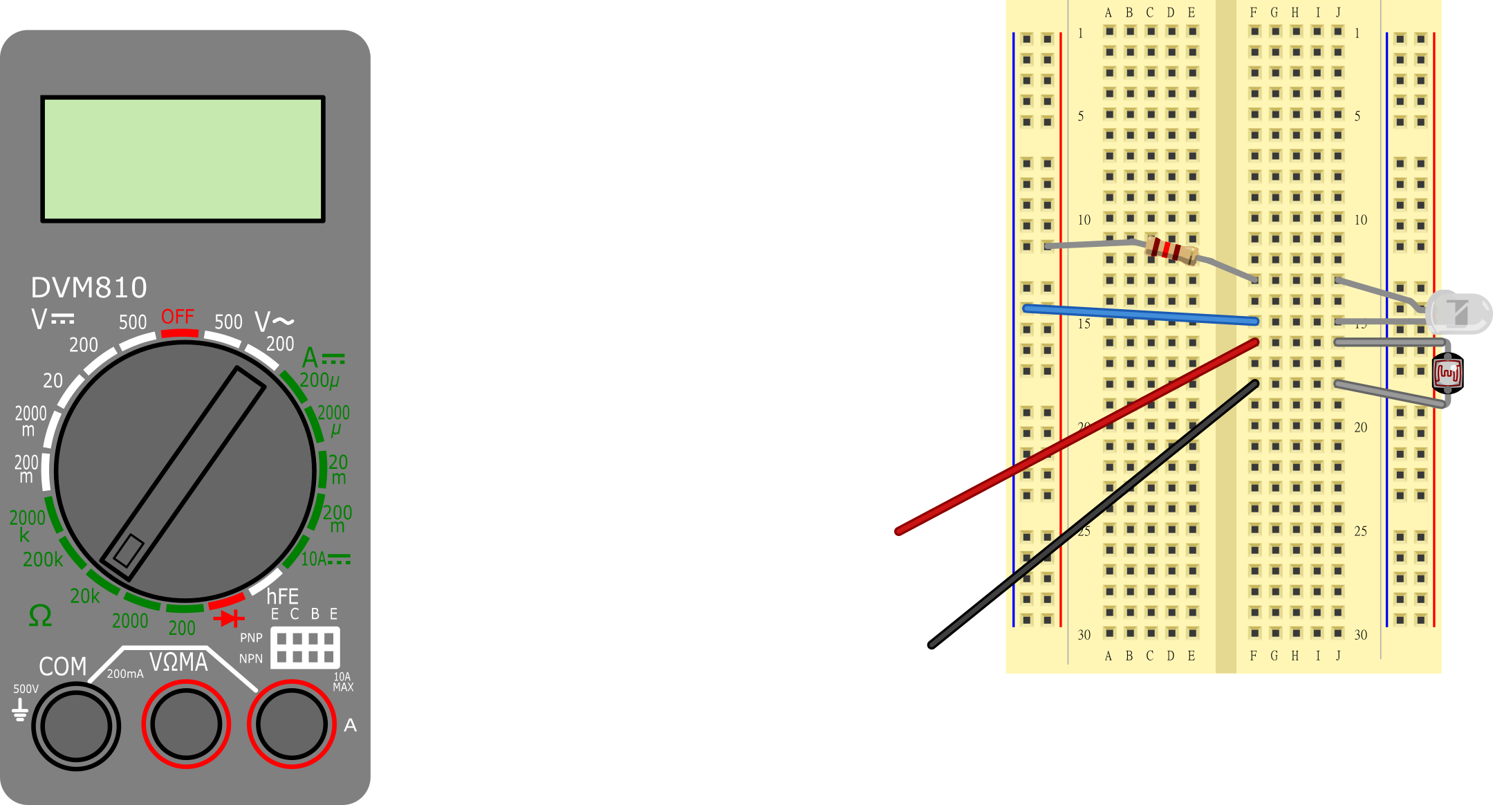
| Multimeter | Insert black probe into COM port. Use alligator clip to connect it to jumper wire from F18 Insert red probe into VΩMA port. Use alligator clip to connect it to jumper wire from F16 Set dial to "20k" |
|
| 3xAA battery pack | Black wire to (-) bus (blue line on breadboard) Red wire to (+) bus (red line on breadboard) |

- Set up the experiment as shown in Figure 4.
- Tape your breadboard to a piece of cardboard.
- Tape a cardboard box about 1 cm away from the edge of the breadboard. The exact distance does not matter, as long as it remains constant throughout your experiment.
- Bend the LED and photoresistor 90° to the side, so they both face the cardboard box.
- Cut a small piece of black construction paper and tape it around the edge of the photoresistor, so only the front face is exposed. This will help the photoresistor primarily measure reflected light, and not ambient light coming from other directions.
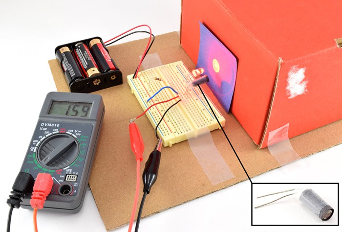 Image Credit: Ben Finio, Science Buddies / Science Buddies
A battery pack powers an LED that shines a light at a colored paper. A light sensor directly beneath the LED measures the light reflected off of the piece of paper and a multimeter reads the output given from the light sensor.
Figure 4. Experimental setup for the light-measuring circuit.
- Cut squares (roughly 6x6 cm) from black, white, red, blue, and green pieces of construction paper. Test that you can prop the squares of paper flat up against the cardboard box without them falling over. If necessary, you can use tape to hold them in place.
- Even with the black construction paper wrapped around it, the photoresistor is still sensitive to ambient light levels. It is important that you do the experiment in a room with constant ambient light levels. For example, avoid doing the experiment on a partially cloudy day in a room with lots of windows, as light levels may fluctuate when clouds pass in front of the sun.
- Create a data table like Table 2 in your lab notebook.
| Resistance (kΩ) | ||||
|---|---|---|---|---|
| Paper Color | Trial 1 | Trial 2 | Trial 3 | Average |
| Black | ||||
| White | ||||
| Red | ||||
| Green | ||||
| Blue | ||||
- Double-check your circuit. Make sure the battery pack is on, the LED is on, and your multimeter is connected and set to measure resistance in the 20 kΩ range.
- Place a black square of construction paper against the box in front of the resistor and LED. Read the resistance from your multimeter and record it in your data table.
- Repeat step 7 for each of the other colors.
- Repeat steps 7–8 two more times, for a total of three trials with each color.
- Calculate an average resistance value for each color and make a bar graph of your results.
- Analyze your results.
- Do you see a large difference in resistance between any two colors?
- Do any colors have about the same resistance?
- Imagine that the resistance value was the only information you had available (you could not actually see the surface you were measuring). Could you identify the color of the surface from that value alone?
Build a Circuit to Differentiate Red and Green Produce
In this section, you will use the information you learned in the previous section to build a circuit that can differentiate between red and green produce. It will light a second LED when red produce is placed in front of it, and the LED will stay off when green produce is placed in front of it (Figure 5). You will need to make some adjustments to get the circuit working perfectly. See the technical note for a more detailed explanation of how the circuit works (you do not need to fully understand how the circuit works in order to complete the project).
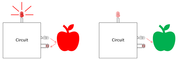 Image Credit: Ben Finio, Science Buddies / Science Buddies
Color detection circuit concept showing two apple and two detectors. In the left-hand circuit, the detector shines LED light on a red apple, and a red LED activates singaling that the color red was detected. In the right-hand circuit, an LED light shines on a green apple, and the detector does not light (indicating that a different wavelength was detected).
Figure 5. Concept for a color-detecting circuit to separate ripe (red) and unripe (green) produce.
Figure 6 shows the circuit diagram for this circuit. It uses several additional parts that you did not use in your first circuit. See the advanced section of the bibliography to learn more about these components.
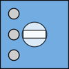
- A potentiometer is a type of variable resistor. Its resistance can be adjusted by twisting a knob. The potentiometer is used to adjust your circuit's sensitivity to light.
- The potentiometer is combined with the photoresistor to form a voltage divider. A voltage divider uses two resistors to take an input voltage (V1 in Figure 6) and reduce (or "divide") it by a certain amount. The output voltage (V2) depends on the values of the two resistors. In this circuit, those resistances depend on how much light is hitting the photoresistor, and how you have adjusted the potentiometer knob respectively. When more light hits the photoresistor, the output voltage goes up.
- The output of the voltage divider is sent to the input of a transistor. A transistor acts like a valve that can control the flow of electrical current through something else, like a motor, buzzer, or LED. In this circuit, when the input voltage to the transistor exceeds a certain threshold (which occurs when enough light is reflected back to the photoresistor), it will cause a second LED to turn on.
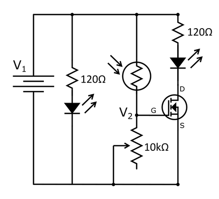 Image Credit: Ben Finio, Science Buddies / Science Buddies
Figure 6. Schematic for the color-detector circuit. If you do not know what these symbols mean, see the "How to Read a Schematic" reference in the bibliography.
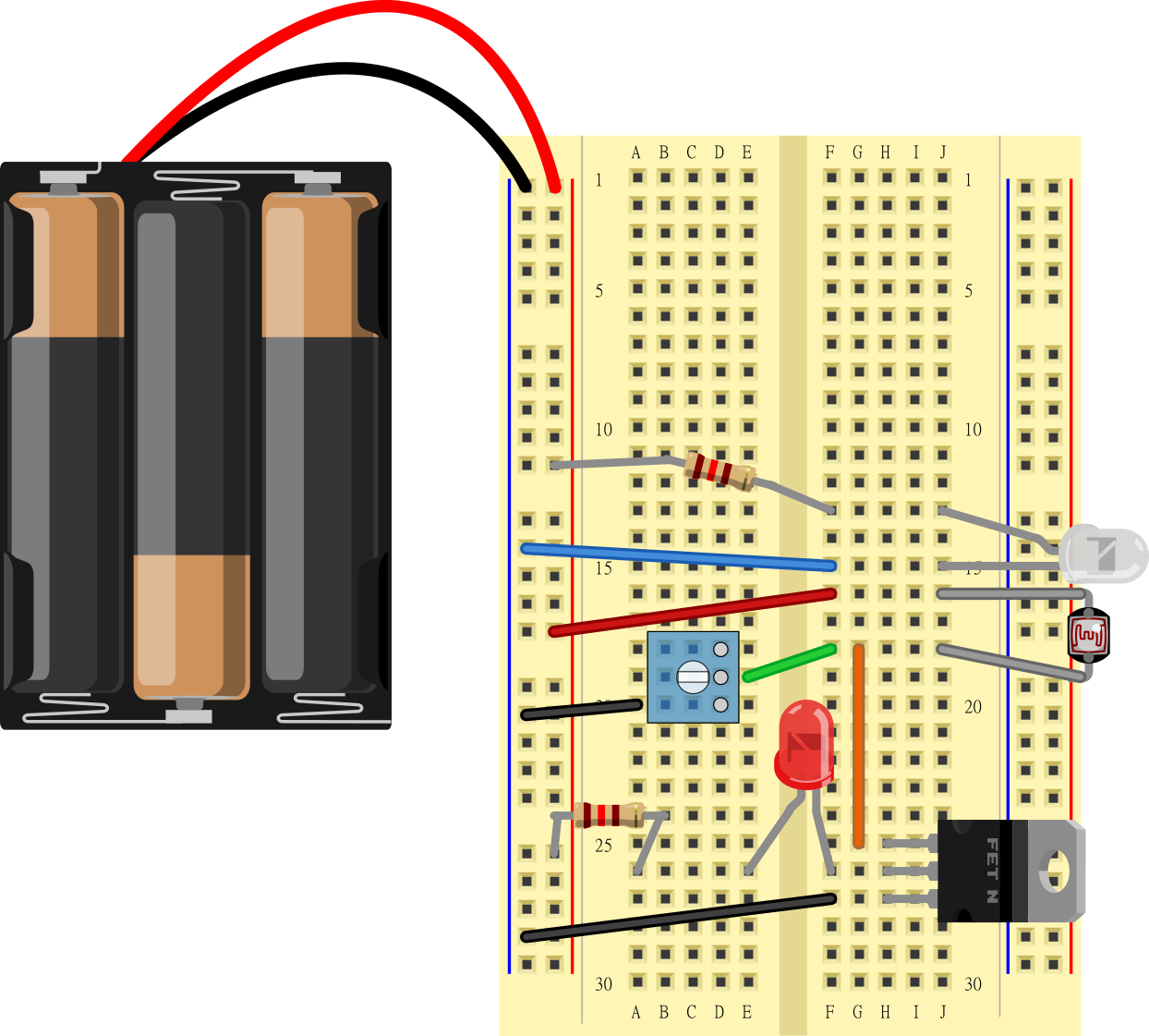
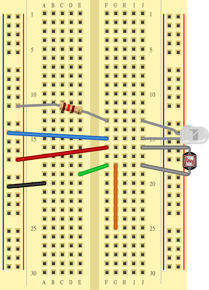
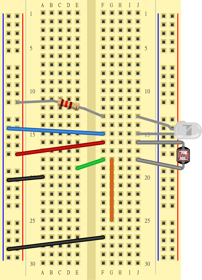
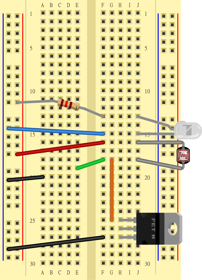
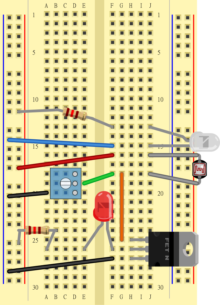
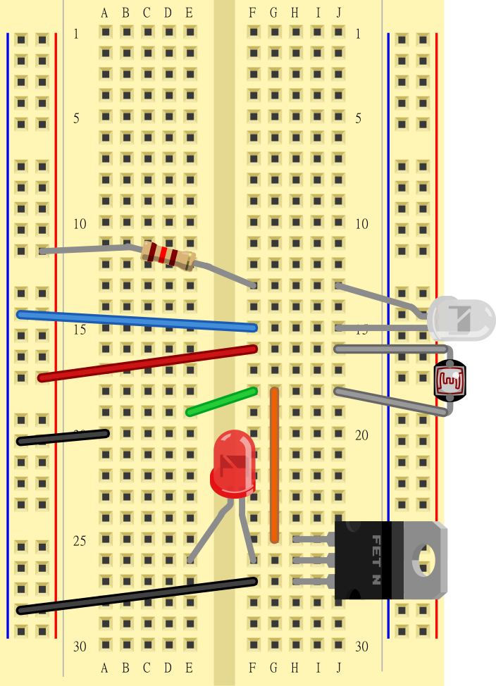
- Assemble your new circuit as shown in the slideshow (make sure you read the captions!) and Table 3. Disconnect the battery pack while you are building your new circuit, and reconnect it at the end.


| Part | Picture | Notes |
|---|---|---|
| Photoresistor | J16 to J18 Direction does not matter |
|
| 120 Ω resistor | (+) bus to F13 Direction does not matter |
|
| Clear red LED | Long leg to J13 Short leg to J15 Direction matters; your LED will not light up if you get the two legs reversed! |
|
| Jumper wires (6 total) | (-) bus to F15 (+) bus to F16 (-) bus to A20 (-) bus to F27 E19 to F18 G18 to G25 Color does not matter |
|
| Transistor | With writing facing to the left, pins in H25, H26, H27. Direction matters! |
|
| Diffused red LED | Long leg to E26 Short leg to F26 Direction matters! |
|
| 120 Ω resistor | (+) bus to A26 Direction does not matter |
|
| Potentiometer | Holes D18, D19, D20 | |
| 3xAA battery pack | Black wire to (-) bus (blue line on breadboard) Red wire to (+) bus (red line on breadboard) |

- Now you will make some adjustments to get your circuit working properly. As described in the technical note, the diffused LED will turn on when the voltage V2 in the circuit exceeds a certain threshold. This voltage depends on two different factors:
- The resistance of the potentiometer, which you can adjust by turning the knob. This allows you to tune your circuit's sensitivity to light. The farther clockwise you turn the potentiometer, the more light is required to turn on the diffused LED.
- The resistance of the photoresistor, which gets lower when more light hits it. When the photoresistor's resistance is low enough, the diffused red LED will turn on. The exact amount of light hitting the photoresistor depends on many factors, such as:
- The distance to the surface being measured.
- The angle of the surface being measured (more light will be reflected back if the surface is perpendicular to light from the LED than if it is at a sharp angle).
- The relative position and orientation of the photoresistor and clear red LED.
- Ambient light levels in the room.
- How the photoresistor is shielded (for example, using black construction paper) from ambient light and direct (as opposed to reflected) light from the clear red LED.
- Your goal is to adjust the circuit such that the diffused red LED will only light up when you hold a piece of red produce in front of the clear red LED and photoresistor, but not when you use a piece of green produce, as shown in Figure 5. This lets you quickly identify whether a piece of produce is ripe just by looking at the LED. You can imagine how such a machine would be useful in a factory or farming setting to quickly and automatically identify, harvest, or sort ripe fruits and vegetables. Try adjusting some of the factors in the previous step to see if you can get the circuit to work to identify red and green produce. It may help to practice with squares of red and green construction paper first. How reliable is your circuit? Does it ever give a false positive (identify green produce as red) or a false negative (identify red produce as green)? See the variations section for more ideas about how to improve or modify your circuit.
Ask an Expert
Global Connections
The United Nations Sustainable Development Goals (UNSDGs) are a blueprint to achieve a better and more sustainable future for all.

Variations
- Try this project with a different color LED. For example, use a super bright green LED (Jameco part #2077079, use with 68 Ω resistor, part #690582) or blue LED (Jameco part #183222, use with 47 Ω resistor, part #690540). Note that these LEDs have a higher forward voltage drop so you will need to replace the 120 Ω resistor in the circuit as noted. How do your results change if you use a different color LED?
- Try testing your circuit on a broader range of colored surfaces (yellow, cyan, magenta, orange, pink, etcetera). What colors result in similar resistance values? What colors result in different resistance values? What colors can you use your circuit to clearly differentiate?
- How do your results change with varying ambient light levels? Does the circuit work outside in direct sunlight? What about in a busy room where people walk by and cast shadows on the circuit? How realistic would it be to use the circuit in different settings, for example a setting with controlled lighting (inside a factory) versus an outdoor area like a field?
- The circuit in this project is not designed to identify all possible colors. It is designed to differentiate between two known colors (meaning you assume you will only show the circuit red or green tomatoes, and that you will never show it a blue tomato). Can you design a circuit that can detect any color? Hint: your circuit will need three LEDs (the red LED from the materials list, and the blue and green LEDs listed in the first variation), or a single RGB LED (an LED with red, green, and blue LEDs all built in to the same packaging). This task may be much easier with a microcontroller such as the popular Arduino™. Search online for "Arduino color detector circuit" or "Arduino color sensor" and you will find many examples.
- Can you accomplish color detection using a webcam and computer vision instead of a circuit? What are the advantages and disadvantages of each approach?
- As discussed in the background, there are other ways that you can tell if produce is ripe, like size, firmness, or smell. Can you design a different circuit that uses one of these methods to detect ripe produce? A photoresistor is an example of an electronic sensor that measures light. There are a variety of other sensors available that can measure things like distance, pressure, or the presence of certain gases. Do some research on these sensors and determine which ones you could use.
Careers
If you like this project, you might enjoy exploring these related careers:


Related Links
- Science Fair Project Guide
- Other Ideas Like This
- Electricity & Electronics Project Ideas
- Plant Biology Project Ideas
- Agricultural Technology Project Ideas
- My Favorites

