Abstract
How fast can a human driver react and hit the brakes when there is an obstacle in the road? Can autonomous cars react more quickly and make the road safer for everyone? In this project you will build your own Arduino robot and test human braking versus automatic braking as the robot drives toward an obstacle at full speed.
Summary
Previous experience with circuits and Arduino is recommended.
Bluebot 4-in-1 robotics kit and Electronics Kit for Arduino available from our partner Home Science Tools®. See materials list for details.
No issues
Valuable input provided by Analog Devices employees.
/-/https/i.ytimg.com/vi/lW-mS-4qUz8/maxresdefault.jpg)
Objective
Find out whether automatic braking is faster than manual braking using a robot as a model of a driverless car.
Introduction
Autonomous, self-driving, or driverless cars have the potential to reduce traffic fatalities and traffic congestion worldwide. A fully autonomous car would be capable of driving in all situations, without any input from a human driver. While cars have not yet achieved this level of autonomy, many new cars have a variety of driver-assist and safety features, such as automatic braking, lane departure warnings, and adaptive cruise control. Some have more autonomy and are able to self-drive in specific situations, such as highways with well-marked lanes. Tesla is an example of a car company known for making cars with some autonomous driving features (Figure 1).
/-/https/www.sciencebuddies.org/cdn/Files/18249/19/tesla-car.jpg)
Figure 1. A Tesla, a type of car with some autonomous driving features.
Just as humans use our senses (sight, sound, touch, etc.) to perceive the world around us when driving, autonomous cars use a variety of electronic sensors to monitor the roadway and surroundings. Cameras work with complex computer vision systems to process visual information, while radar or ultrasonic sensors measure the distance between the car and other objects. Based on information from these sensors, the car decides how to react—without input from the driver. For example, if a sensor detects that the car in front of it is rapidly slowing down, the car may automatically apply the brakes in order to slow down and avoid a collision. Or if the sensors detect that the car is driving out of its lane and off the side of the road, the car may automatically correct its steering to stay in the lane.
In this project you will build your own autonomous Arduino robot with an ultrasonic sensor that can measure the distance to obstacles in front of the robot. You can use the readings from this sensor to tell the robot to stop if it is too close to an obstacle.
You will test two scenarios. In one, you will tell the robot to stop automatically. In the other, you will tell it to wait for input from a human. For each scenario, you will record the distance the robot travels before coming to a complete stop.
Finally, you will compare the stopping distances for the two scenarios and consider the implications. How much does human reaction time affect the robot's stopping distance? How would this affect a full-size car going full speed on the highway?
Terms and Concepts
- Autonomous vehicle
- Self-driving car
- Driverless car
- Automatic braking
- Lane departure warning
- Adaptive cruise control
- Sensor
- Radar
- Ultrasonic
Questions
- How fast is the typical human reaction time?
- How far does a car traveling at highway speeds (e.g., 65 mph) go in that amount of time?
- Do you think robots can react faster than humans?
Bibliography
General electronics references:
- Science Buddies (n.d.). How to Use a Breadboard. Retrieved July 6, 2020.
- Science Buddies (n.d.). How to Use a Multimeter. Retrieved July 6, 2020.
- Science Buddies (n.d.). Wire Stripping Tutorial. Retrieved July 6, 2020.
References for using an Arduino:
- Science Buddies (n.d.). How to Use an Arduino. Retrieved July 6, 2020.
- Arduino (n.d.). Language Reference. Retrieved July 6, 2020.
Datasheet for the L293D H-bridge motor driver:
- Texas Instruments (January 2016). L293x Quadruple Half-H Drivers. Retrieved July 8, 2020.
Datasheet for the IR sensor:
- Everlight Electronics Co., Ltd. (2007, April 4). Technical Data Sheet Opto Interrupter. Retrieved October 2nd, 2019.
Datasheet for the ultrasonic distance sensor:
- ElecFreaks (n.d.). Ultrasonic Ranging Module HC-SR04. Retrieved October 23, 2023.
Materials and Equipment 
Recommended Project Supplies
/-/https/www.sciencebuddies.org/cdn/Files/9118/11/bluebot-motion-activated-googly-1100_1.png)
Supplies to build your robot:
- BlueBot 4-in-1 Robotics Kit, available from our partner Home Science Tools®. The kit includes a robot chassis, a breadboard, wheels, motors, batteries, and circuit parts to build four different robots.
-
Electronics Kit for Arduino, available from our partner Home Science Tools®.
- Note: This project will work with the Arduino UNO R3, UNO R4 Minima, UNO R4 WiFi, and compatible third-party boards.
- Windows or Mac computer. See this page if you have a Chromebook. Your computer will need:
- Access to the Arduino IDE, either installed local version or web-based editor (note that Chromebooks can only use the web version). Watch this video for a comparison of the two options.
- USB port. The Science Buddies kit comes with a USB-A to B cable. The "B" end plugs into the Arduino and the "A" end plugs into your computer. You will need an adapter or different cable if your computer only has USB-C ports. Watch this video to learn about the different types of cables and adapters.
- Additional recommended tools for working with circuits:
- Digital multimeter for help with troubleshooting (strongly recommended)
- Alligator clip leads to easily connect multimeter probes to the circuit
- Needle nose pliers or tweezers make it easier to handle small parts
- Wire strippers to cut wires to custom lengths, keeping your circuit neater
- Double-sided foam tape
- Craft sticks
Parts to build a wired "remote" for your robot:
- Mini breadboard
- 22 AWG stranded wire (at least 6 feet)
- Momentary pushbutton
Additional supplies for the experiment:
- Open space on a hard floor (not carpet)
- Solid object with a flat surface to use as an obstacle (trash can, cardboard box, etc.)
- Meterstick
Disclaimer: Science Buddies participates in affiliate programs with Home Science Tools®, Amazon.com, Carolina Biological, and Jameco Electronics. Proceeds from the affiliate programs help support Science Buddies, a 501(c)(3) public charity, and keep our resources free for everyone. Our top priority is student learning. If you have any comments (positive or negative) related to purchases you've made for science projects from recommendations on our site, please let us know. Write to us at [email protected].
Experimental Procedure
- Assemble your Bluebot chassis.
Follow the instructions in this video; however, instead of mounting the 4xAA battery pack on top of the robot, mount it on the lower plate. Then mount your Arduino next to the breadboard on the top plate. This will give you easier access to the circuit when connecting it to the Arduino.
- Attach the ultrasonic sensor.
Mount the sensor to the front of your robot using a craft stick and double-sided tape, as shown in Figure 2. Make sure the pins are facing up; this will make it easier to connect the jumper wires.
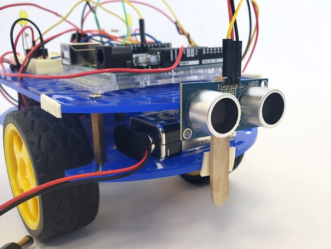
Figure 2. Ultrasonic sensor mounted to the front of the robot. - Assemble your circuit.
If you plan to use the example code provided by Science Buddies, assemble the circuit as shown in Figures 3 and 4. The Arduino pins used in this diagram match the ones used in our example code. If you try to use our example code without matching this wiring diagram exactly, the code will not work properly.
Take your time and carefully double-check all of your wiring. This is a complicated circuit with a lot of connections. You should connect the batteries last to avoid the risk of creating short circuits while you work.
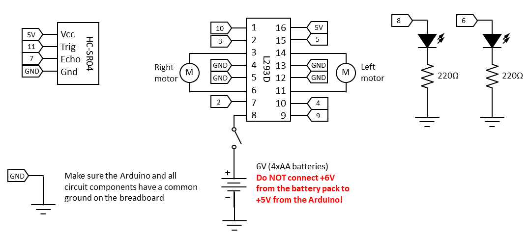
Note: It is important to make sure all components in the circuit have a common ground, but you must be very careful not to short different positive voltages together (e.g., 5 V from the Arduino and 6 V from the 4xAA battery pack).
Following is one suggested order in which you can build the circuit, but you do not need to do it in this order.
Note: Connections are made with male-male jumper wires unless otherwise indicated.
- Connect the left and right ground buses on the breadboard. Do not connect the two power buses. You will use them for different voltages.
- Connect the Arduino's GND pin to the breadboard's ground bus.
- Connect the Arduino's 5 V pin to the breadboard's right-side power bus.
- Pins on the L293D H-bridge are numbered 1–16, counterclockwise from the top left. Connect them as follows:
- Pin 1 to Arduino pin 10
- Pin 2 to Arduino pin 3
- Pin 3 to the right motor's negative wire
- Pin 4 to ground
- Pin 5 to ground
- Pin 6 to the right motor's positive wire
- Pin 7 to Arduino pin 2
- Pin 8 to the left-side power bus (which will be connected to 6 V later)
- Pin 9 to Arduino pin 9
- Pin 10 to Arduino pin 4
- Pin 11 to the left motor's positive wire
- Pin 12 to ground
- Pin 13 to ground
- Pin 14 to the left motor's negative wire
- Pin 15 to Arduino pin 5
- Pin 16 to 5 V
- Connect the ultrasonic sensor using male-female jumper wires.
- GND pin to ground
- 5V V pin to 5 V
- Trig pin to Arduino pin 11
- Echo pin to Arduino pin 7
- Connect an LED with a 220 Ω current-limiting resistor between Arduino pin 8 and ground.
- Connect an LED with a 220 Ω current-limiting resistor between Arduino pin 6 and ground.
- Finally, connect the 4xAA battery pack to your circuit.
- Connect the negative wire to the breadboard's ground bus.
- Instead of connecting the positive wire directly to the left-side power, connect it to a switch on the breadboard first, then connect the switch to the left-side power bus (assuming you previously connected the right-side power bus to 5 V; remember not to short the two voltages together). This will allow you to easily turn the battery pack on and off.
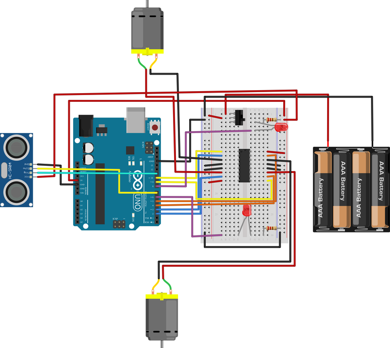
Figure 3. A breadboard view of the circuit. Click for a larger version of the breadboard view.
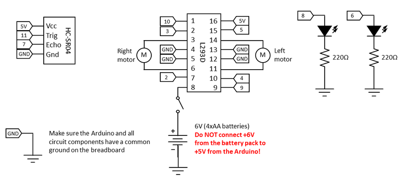
Figure 4. A schematic view of the circuit. Click for a larger version of the schematic view. - Download and review the automatic braking code for your autonomous vehicle.
Carefully read through the commented code. This code makes the robot drive forward at full speed until it detects an obstacle closer than a certain distance; then it will automatically stop.
- Set up your experiment.
Place the meterstick against an obstacle as shown in Figure 5. Make sure the obstacle is large and has a flat surface so it can be easily detected by the sensor. Aim the robot toward the obstacle.
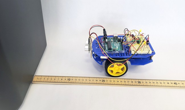
Figure 5. Experimental setup. - Calibrate your ultrasonic sensor.
- Make sure the power switch on the breadboard is turned off—that way your robot's wheels will not spin.
- Upload the code to your Arduino, but keep the Arduino connected to the USB cable.
- Open the serial monitor (Tools→Serial monitor). It will print out the reading from the ultrasonic sensor in centimeters.
- Place your robot next to the meterstick and aim it toward the obstacle. Measure the distance from the front of the sensor to the obstacle. Compare this to the reading displayed on the serial monitor. Record both values and note any difference between them.
- Manually move the robot back and forth. The LEDs should light up when the robot is less than 30 cm from the obstacle. (This is the default value in the example program, but you can change it).
- Calibrate your robot's steering.
- Pick up the robot and turn the power switch on. The wheels should start spinning.
- Put the robot down far away from the obstacle (at least 60 cm) and watch it drive.
- If the robot does not drive straight, change either the speedL or speedR variable in the code as needed. For example, if the robot turns slightly to the right, decrease the speedL variable to make the left wheel spin slower.
- Re-upload your code and try again. Repeat until your robot drives straight.
- Prepare to collect data.
You are almost ready to start collecting data! Make a data table like Table 1.
- Target Final Distance is the desired distance from the obstacle at which you want to stop. By default, this is 30 cm in the example program.
- Actual Final Distance is the final physical distance between the obstacle and the front of the ultrasonic sensor. Measure with the meterstick once the robot has come to a complete stop.
- Stopping Distance is the distance the robot traveled from the point where the sensor detected an obstacle at the target distance to the point where the robot came to a complete stop. To find this value, subtract the actual distance from the target distance.
Table 1. Example data table.Braking type
(automatic or manual)Target Final Distance
(cm)Actual Final Distance
(cm)Stopping Distance
(cm) - Test your robot's automatic braking.
Pick your robot up and place it far enough back that it will have time to accelerate to full speed. Aim it straight toward the obstacle from about 50–60 cm away. Let the robot go. After it stops, measure the actual final distance to the obstacle and record this value in your data table.
Repeat this step at least four more times, for a total of five trials with automatic braking.
- Build a manual braking switch.
This wired "remote" with a button will let you manually activate the brakes on your robot. When the robot detects an obstacle at the target distance, it will no longer brake manually; instead, its lights will come on and it will wait for you to push the button to make it stop.
- Cut two pieces of stranded wire that are each at least 1 m long. Strip the ends of the wires.
- Since the stranded wire is too flexible to push into a breadboard, use needle-nosed pliers to twist and crimp the ends of the stranded wire onto pieces of solid-core jumper wire (Figure 6). For a better connection, use a soldering iron if you have one available. You can also wrap the connections in electrical tape or heat-shrink tubing to prevent short circuits. If you do not, make sure the exposed wires do not bump into each other.
- Place a button on a mini breadboard to use as a "remote" and connect it to your main breadboard as shown in Figures 7 and 8.
- Connect one of the button's wires directly to 5 V.
- Connect the other wire to Arduino pin 12, with a 10 kΩ pull-down resistor to ground.
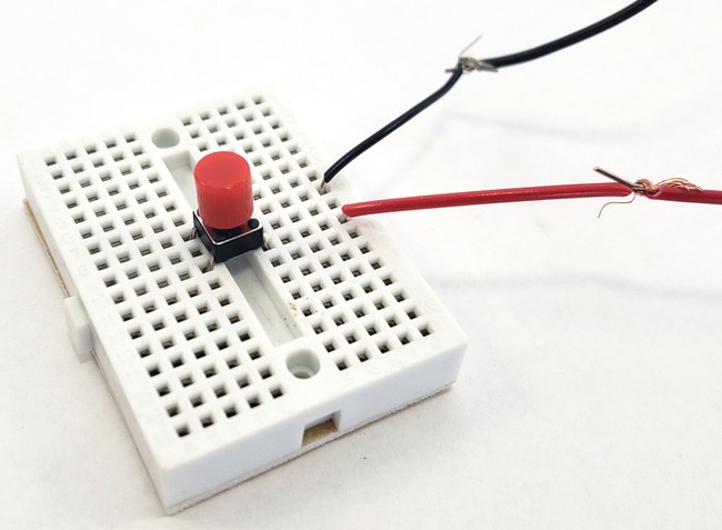
Figure 6. A "remote" for the robot made with a button on a mini breadboard.
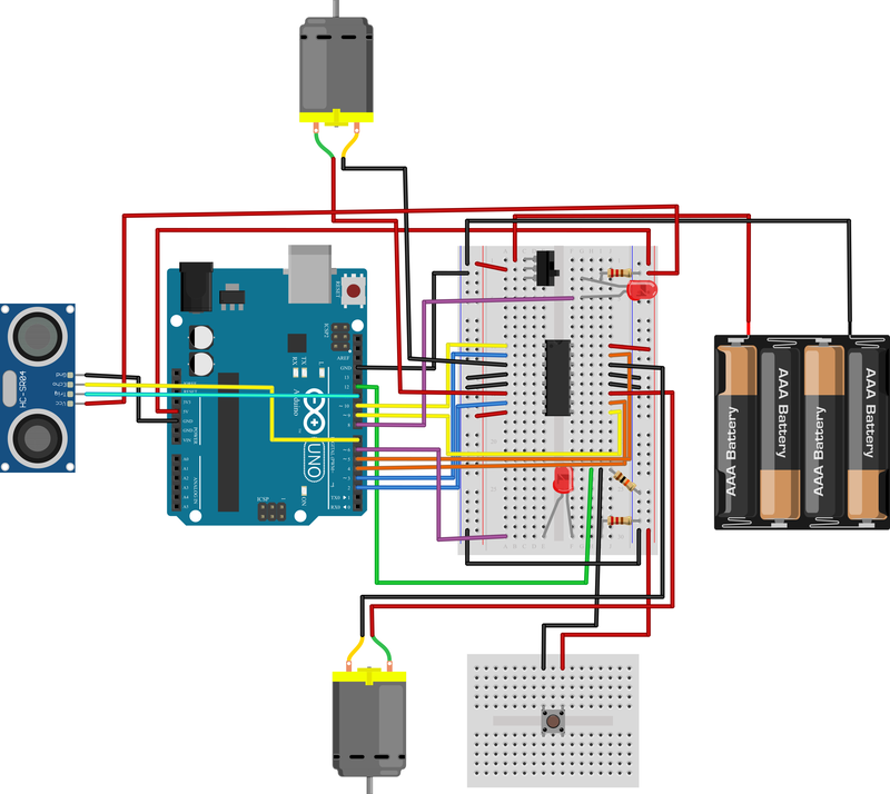
Figure 7. Breadboard view that includes the mini breadboard remote connected to the circuit. Click for a larger version of the breadboarad view.
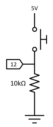
Figure 8. Schematic view for the button. - Download and review the manual braking code for your autonomous vehicle.
Read through the commented code. Make sure you understand the differences between this program and the one for automatic braking.
- Test your robot's manual braking.
Aim your robot toward the obstacle and hold on to the remote with one hand (Figure 9). Make sure the wires connecting the remote to the robot are loose and not tangled. Let go of the robot and carefully watch it drive forward.
When you see the LEDs light up, press and hold the button.
Note: Make sure you wait for the lights; do not try to anticipate the sensor. If it helps, you can remove the meterstick until the robot has stopped.
Record the final distance to the obstacle in your data table.
Repeat this step at least four more times, for a total of at least five trials with manual braking.
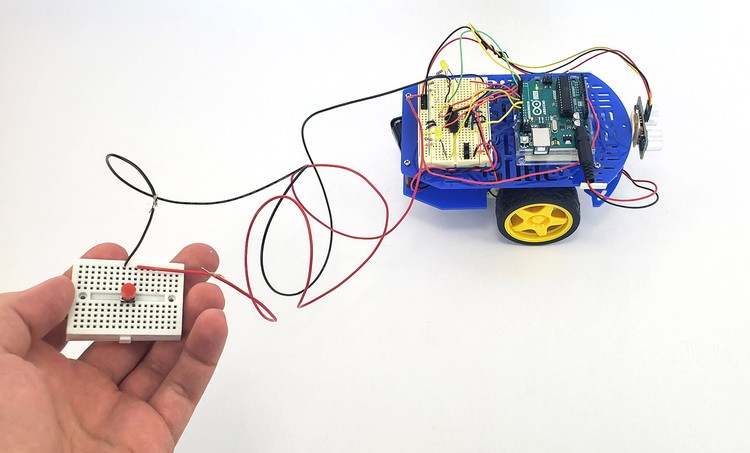
Figure 9. Robot with remote button for manual braking. - Analyze your results.
- Calculate average stopping distances for both automatic braking and manual braking. How do the two values compare?
- Think about your results in the context of a full-sized vehicle. How can human reaction time influence the stopping distance of a car traveling at highway speeds?
- How could distractions that increase reaction time (e.g., cell phone use) affect stopping distance?
/-/https/i.ytimg.com/vi/SBeGl_IgWwY/maxresdefault.jpg)
/-/https/www.sciencebuddies.org/cdn/Files/18298/11/ultrasonic-sensor-mounted.jpg)
/-/https/www.sciencebuddies.org/cdn/Files/18299/20/autonomous-braking-breadboard-fig3.png)
/-/https/www.sciencebuddies.org/cdn/Files/18300/15/automatic-braking-circuit-diagram.png)
/-/https/www.sciencebuddies.org/cdn/Files/18301/11/autonomous-car-braking.jpg)
/-/https/www.sciencebuddies.org/cdn/Files/18302/11/mini-breadboard-button-remote.jpg)
/-/https/www.sciencebuddies.org/cdn/Files/18303/23/autonomous-braking-breadboard-fig7.png)
/-/https/www.sciencebuddies.org/cdn/Files/18304/11/button-circuit-diagram.png)
/-/https/www.sciencebuddies.org/cdn/Files/18305/11/robot-with-remote.jpg)
Ask an Expert
Global Goals
The United Nations Sustainable Development Goals (UNSDGs) are a blueprint to achieve a better and more sustainable future for all.
/-/https/www.sciencebuddies.org/cdn/Files/19752/5/E-WEB-Goal-09.png)
Variations
- Change the target distance and repeat the experiment. Does this affect your results?
- Does the robot's speed affect the stopping distance? How does this relate to a car's stopping distance on a highway versus a city street?
Careers
If you like this project, you might enjoy exploring these related careers:
/-/https/careerdiscovery.sciencebuddies.org/cdn/Files/928/17/ThomasWallner.jpg)
/-/https/careerdiscovery.sciencebuddies.org/cdn/Files/1725/18/4161_Michelle_Easter_and_Curiousity_Clone.jpg)
/-/https/careerdiscovery.sciencebuddies.org/cdn/Files/1223/17/iStock-971549326.jpg)
/-/https/careerdiscovery.sciencebuddies.org/cdn/Files/1163/18/pexels-photo-1181472.jpg)
Contact Us
Our kits are developed in partnership with Home Science Tools®. If you have purchased a kit for this project, Home Science Tools® is pleased to answer any questions.In your email, please follow these instructions:
- Include your Home Science Tools® order number.
- Please describe how you need help as thoroughly as possible:
Examples
Good Question I'm trying to do Experimental Procedure step #5, "Scrape the insulation from the wire. . ." How do I know when I've scraped enough?
Good Question I'm at Experimental Procedure step #7, "Move the magnet back and forth . . ." and the LED is not lighting up.
Bad Question I don't understand the instructions. Help!
Good Question I am purchasing my materials. Can I substitute a 1N34 diode for the 1N25 diode called for in the material list?
Bad Question Can I use a different part?
Contact Support

/-/https/img.youtube.com/vi/Djzx54j-2ZU/0.jpg)
/-/https/img.youtube.com/vi/jr3BOE_EpOk/0.jpg)
/-/https/img.youtube.com/vi/ksG87OUZOkA/0.jpg)