Wearable Air Quality Sensor
Summary
/-/https/www.sciencebuddies.org/cdn/Files/18904/7/finalized-dust-sensor-thumbnail.jpg)
Introduction
Wearables are found all over the biomedical world: heart rate monitors, EKG patches, braces, etc. In this project, you will make your own wearable air quality sensor that notifies you of high-risk air. You can attach the sensor patch on any existing clothing or even make a standalone patch that you can wear as a necklace or a bracelet.
Materials
Crafting materials:
Tools:
- Needles
- Scissors
- Hot glue gun with refills
- Ballpoint pen
- Needle-nose pliers
- Wire strippers
- Access to computer
Disclaimer: Science Buddies participates in affiliate programs with Home Science Tools®, Amazon.com, Carolina Biological, and Jameco Electronics. Proceeds from the affiliate programs help support Science Buddies, a 501(c)(3) public charity, and keep our resources free for everyone. Our top priority is student learning. If you have any comments (positive or negative) related to purchases you've made for science projects from recommendations on our site, please let us know. Write to us at [email protected].
Prep Work
- Make sure you have the Arduino IDE installed on your computer.
- If this is your first time using an Arduino, see the Science Buddies How to Use an Arduino page. That page is for the Arduino UNO, but the process is similar for a TinyLily board.
Instructions
- This procedure will show you how to build the following circuit, using multiple layers of fabric to help insulate between the wires. There are other ways to construct the circuit, including using a soldering iron and a protoboard, or insulating individual conductive threads when they cross so they do not create a short-circuit.
Swipe left to see moreWiring Key Component Connection 1 Connection 2 Dust sensor red wire Dust sensor LiPo booster board positive '+' pin Dust sensor black wire Dust sensor TinyLily pin A0 Dust sensor yellow wire Dust sensor LiPo booster board negative '-' pin Dust sensor white wire Dust sensor TinyLily pin 3 Dust sensor green wire Dust sensor LiPo booster board negative '-' pin Dust sensor blue wire Dust sensor 150Ω resistor Red led wire 1 Red LED negative '-' pin TinyLily negative '-' pin Red led wire 2 Red LED negative '+' pin TinyLily pin 0 Yellow led wire 1 Yellow LED negative '-' pin TinyLily negative '-' pin Yellow led wire 2 Yellow LED negative '+' pin TinyLily pin 1 Green led wire 1 Green LED negative '-' pin TinyLily negative '-' pin Green led wire 2 Green LED negative '+' pin TinyLily pin 2 Negative wire TinyLily negative '-' pin LiPo booster board positive '+' pin (JST connection) Positive wire TinyLily positive '+' pin LiPo booster board negative '-' pin (JST connection) 220μF capacitor LiPo booster board positive '+' pin LiPo booster board negative '-' pin 150Ω resistor Dust sensor blue wire LiPo booster board positive '+' pin 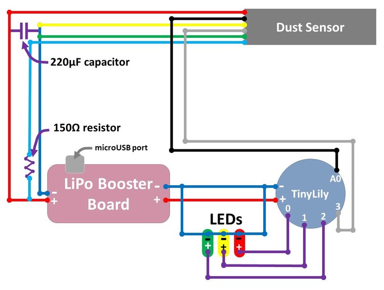
/-/https/www.sciencebuddies.org/cdn/Files/18905/4/circuit-diagram-dust-sensor.jpg)
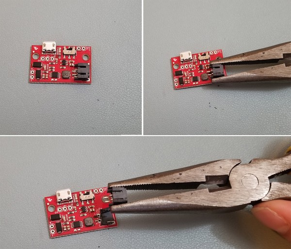
- First, prepare your LiPo booster board. You will not need the JST connector (the connector that would connect the LiPo booster board to the LiPo battery) on your LiPo booster board. Remove the connector with your needle nose pliers. Twist the top off the booster board so that the positive (+) and negative (-) input pins are exposed.
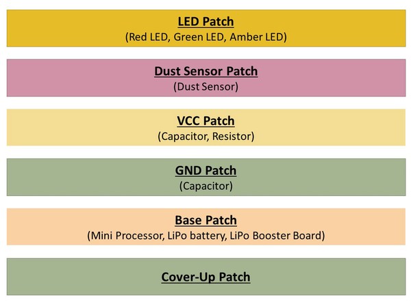
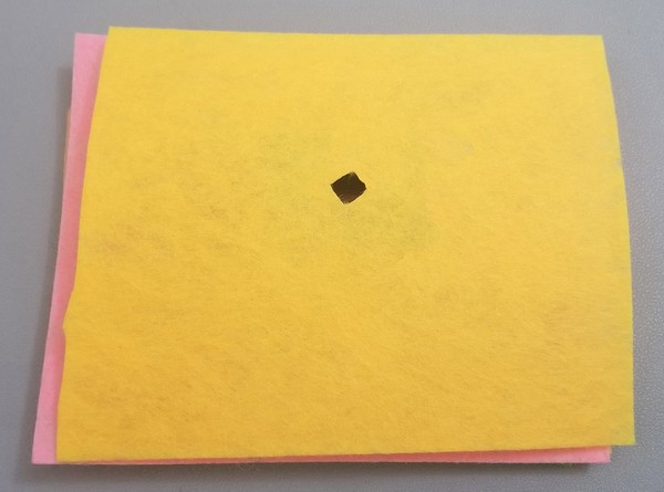
- Prepare your fabric patches. You can choose to make a patch of any shape. Cut six of the same shape from your fabric. The demonstration uses different colored felt sheets to better highlight the different layers. Note the patch should be at least 2"x3" in size. Make sure the electronics can fit.
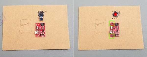
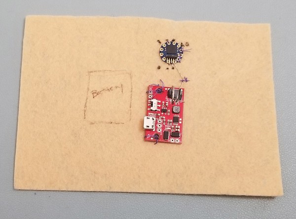
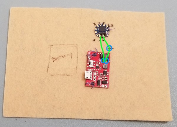
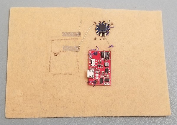
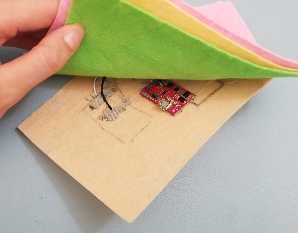
- Begin with base patch which will hold the TinyLily, LiPo battery, and LiPo booster board. Place these parts onto felt piece and trace around them with a pen. Sew the LiPo booster board onto the felt piece with non-conductive thread. Hot glue the TinyLily onto the felt piece. The image shows sewn areas outlined in green and hot glue spots in red.
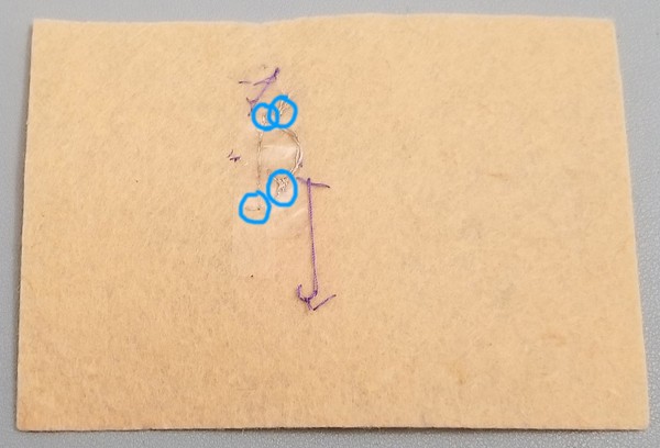
- With conductive thread, sew the '+' from the TinyLily to the '+' of the booster board that originally had the JST connection piece. Next, sew the '-' from the TinyLily to the '-' of the booster board (right next to the previous '+'). In the next image, one of the connections is made on the other side of the felt piece.
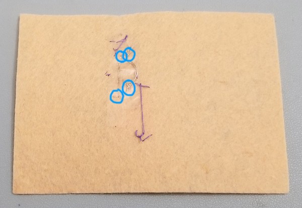
- To prevent any short circuits, hot glue the conductive threads down and apart from each other. Turn your base felt piece over and do the same. Green is to mark the conductive thread paths and blue is to mark points of hot glue.
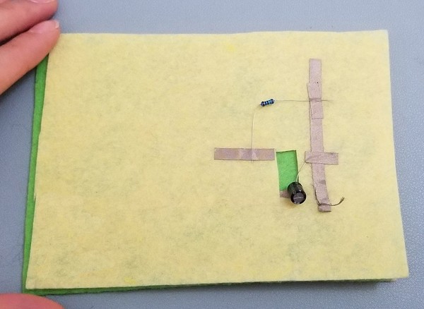
- Place two pieces of one-inch conductive fabric tape parallel to each other above the marked battery spot. One is for pin A0 on the TinyLily and the other is for pin 3 on the TinyLily. Sew from the conductive fabric tape rails to the appropriate TinyLily pins.
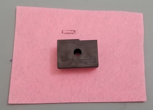
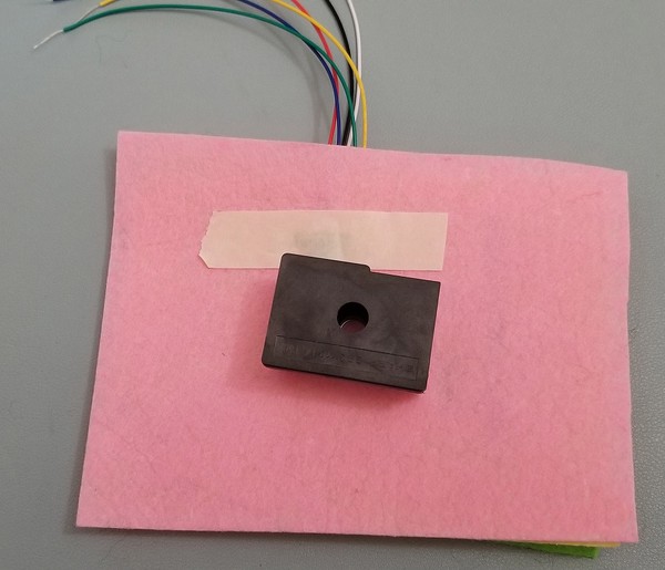
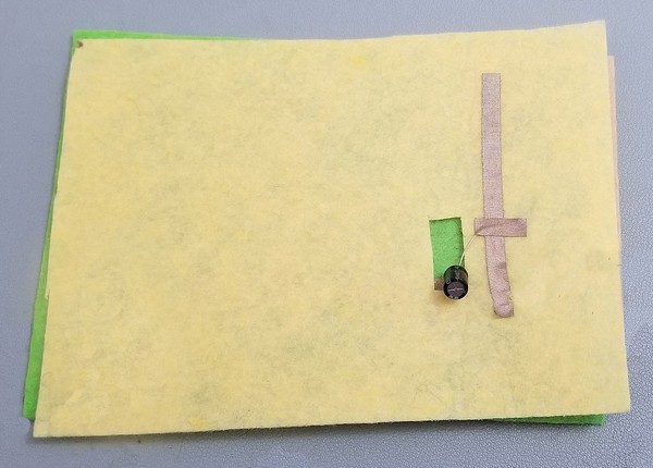
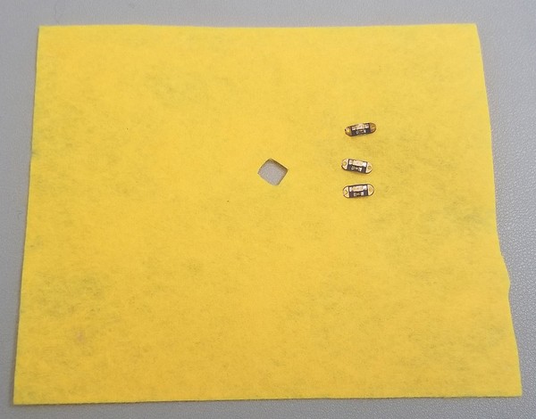
- We will now work on the dust sensor patch. Trim the 6-wire connection piece so that the wire is around 3-4 inches long. Using your wire stripper, strip about an inch of insulation from the end of each wire.
- Plug the 6-wire connection piece into the dust sensor and place on the center of your patch. Cut a narrow rectangle at the top for the 6-wire connection piece to go through. Tape the wires down for extra security.
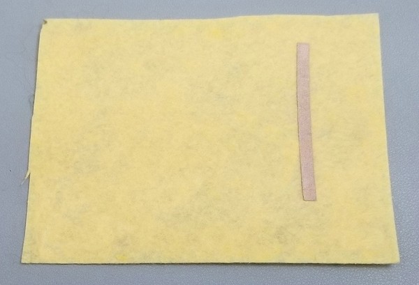
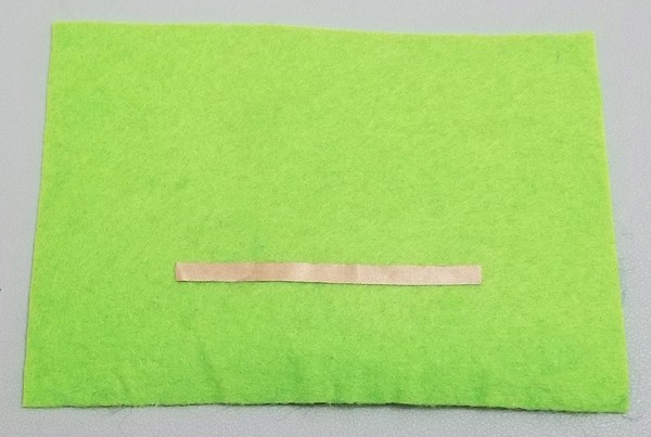
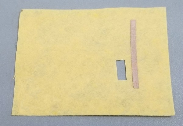
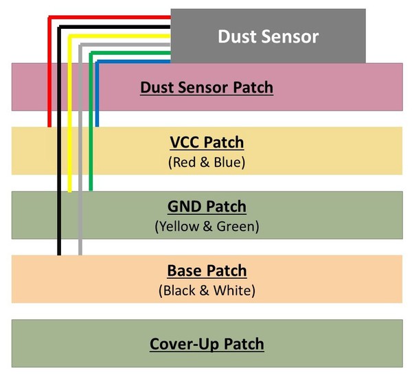
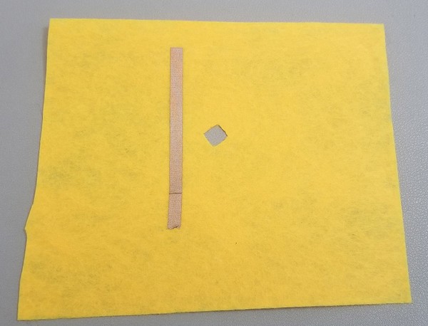
- Select your VCC patch. This is where your 5V wire will go from your base patch. Cut a 1-2 inch strip of conductive fabric tape. Tape it on the VCC patch approximately to the slight right your '+' 5V output on your booster board as a vertical rail.
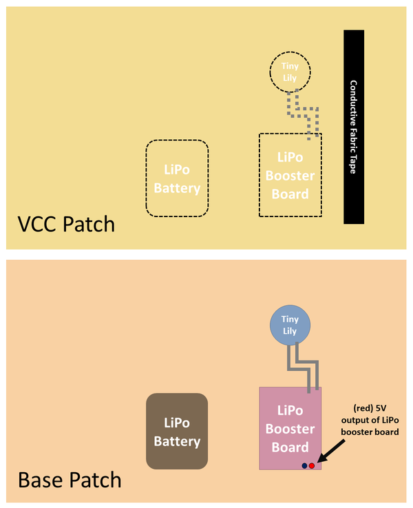
- Select your GND patch. This is where your negative wire will go from your base patch. Cut a 1-2 inch strip of conductive fabric tape. Tape it on the GND patch directly above your '-' output on your booster board as a horizontal rail.
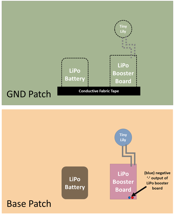
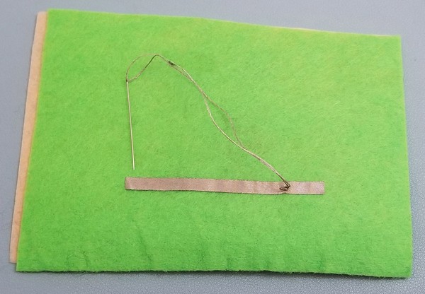
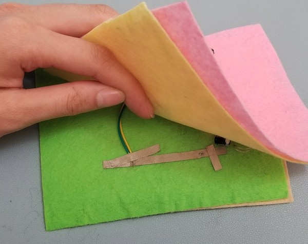
- Stack your GND patch on top of your base patch. Using conductive thread, connect your negative '-' output of the LiPo booster board to the conductive fabric tape rail on the GND patch.
- Using the capacitor from your dust sensor kit, place the shorter capacitor leg on top of the conductive fabric tape rail. Either hot glue the leg onto the rail or use a small piece of conductive fabric tape. After it cools, stack the VCC patch on top of the GND patch. Mark the bump where the capacitor is. Cut a hole big enough for the capacitor go through.
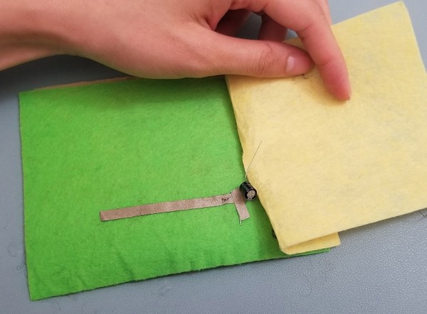
- Thread the capacitor through, place longer capacitor leg on the VCC rail and either tape on with a small piece of conductive fabric tape or hot glue on.
- Sew the '+' 5V output from the LiPo booster board on the base patch up to the positive rail.
- On the VCC patch, tape or hot glue the resistor from your dust sensor kit on to the conductive fabric tape rail. Temporarily tape down the other end of the resistor.
- Thread your dust sensor through to the other layers. For where your six-wire connector should go through, cut a slit in your fabric patches and thread the wires through.
- red and dark blue wires go to the VCC patch
- green and yellow wires go to the GND patch
- white and black wires go to the base patch
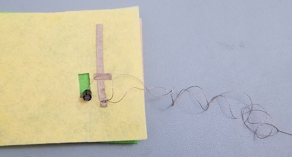
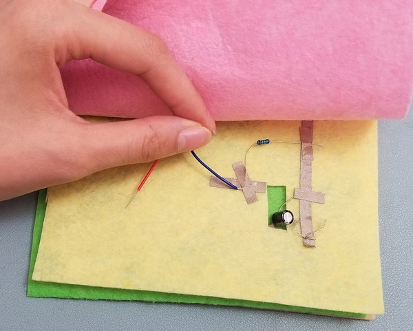
- Connect the white wire to the piece of conductive tape connected to TinyLily pin 3 on the base patch of felt. Do the same for the black wire and connect the black wire to the piece of conductive tape connected to TinyLily pin A0 on the base patch of felt. Tape down with conductive fabric tape or hot glue it down.
- Connect the yellow and green wire to the top of the conductive fabric tape rail on GND patch. Tape down with conductive fabric tape or hot glue it down.
- Connect the red wire to the top of the conductive fabric tape rail on VCC patch. Tape down with conductive fabric tape or hot glue it down. Remove the resistor from under the conductive fabric tape, the non-conductive fabric tape rail end. Connect the blue wire to the free end of the resistor (not the conductive fabric tape rail end). Tape down with fabric tape or hot glue it down. Note that the next image does not have the red wire connected to the right most VCC conductive fabric tape rail yet.
- The capacitor should cause a bump in the dust sensor patch. Cut a small hole for the capacitor to go through to the dust sensor patch.
- Launch the Arduino IDE.
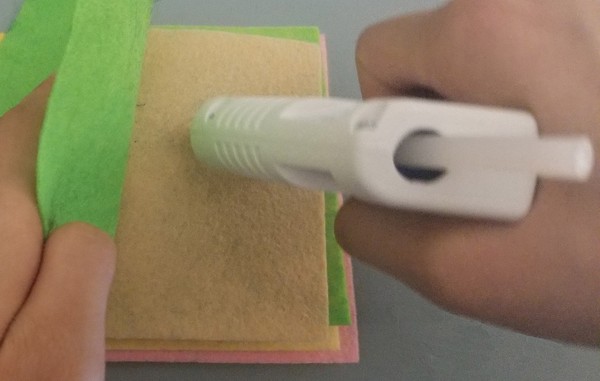
- Attach the TinyLily Mini USB Adapter to the TinyLily then connect to the computer through your microUSB cable.
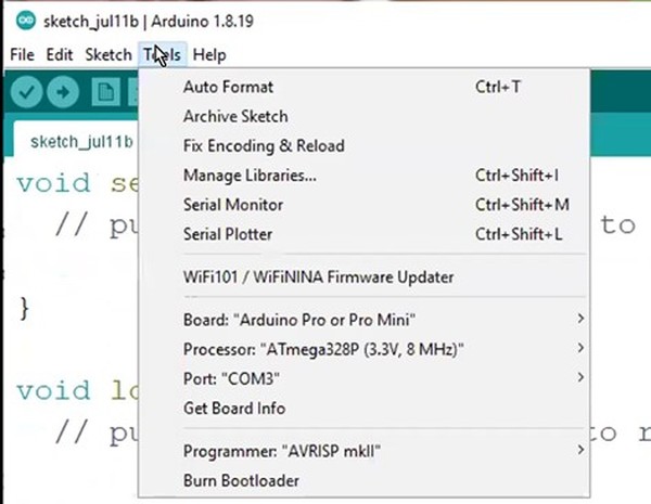
- Go to the top bar: Tools → Board. Click the drop-down menu and select "Arduino Pro or Pro Mini."
- Select Tools→ Processor. Select "ATmega328p (3.3V, 8MHz)." Note: this option will not appear until you have selected "Arduino Pro or Pro Mini" for the board.
- Select Tools→ Port. Select the available port. It should be "COM" followed by a series of numbers. If your computer is a Mac, this would be "dev/cu.usbserial" followed by a series of numbers.
- Download DustSensor.ino and open in the Arduino IDE. Note: The code is based on this Github site code.
- Upload onto your TinyLily.

- Open the Serial Monitor by selecting: Tools → Serial Monitor. A new window should pop up. Set baud to 115200. This is located as a drop-down menu at the bottom of the Serial Monitor.

- Once your Arduino code has successfully uploaded onto your TinyLily, you should see your voltage value and dust density in mg/m3.
- Look at the dust density while you are in still air. It should change very little.
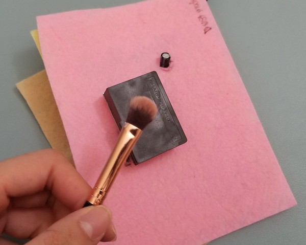
- Try throwing some dust in the air (make up from make up brush, a sprinkle of flour, dusting your pillows, etc.). You should see the dust density in the air increase.
- Negative values in the serial monitor can show up. This is okay. This is due to a calibration issue initially with the dust sensor. You can just assume these negative values as 0 if they are within -0.10. If it is more negative than -0.10, double check your wires.

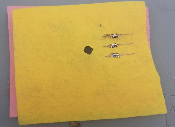
- Disconnect the battery adapter and the microUSB cable from the TinyLily. Stack the LED fabric patch on top of your dust sensor. Cut a hole in the fabric so air can still get into the hole in the dust sensor.
- Flip the LED patch over to its back side. To the left of the hole, place a vertical strip of conductive fabric tape. This is your negative '-' rail.
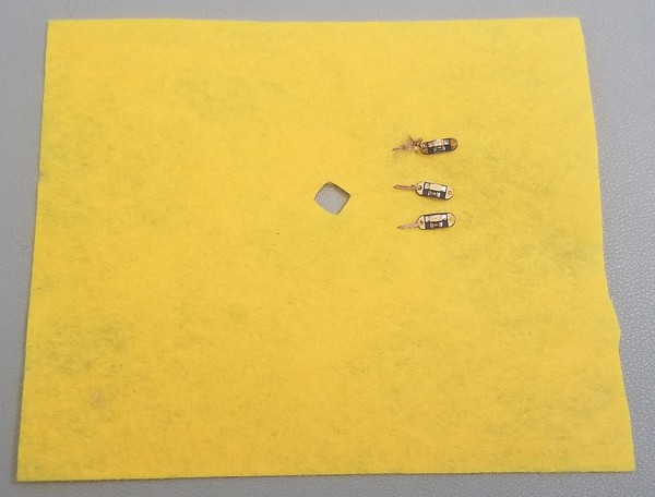
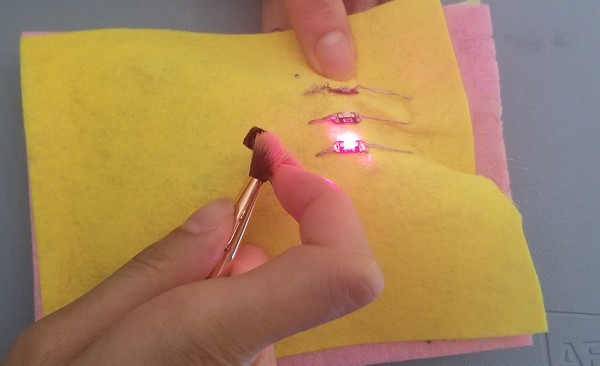
- Flip the LED patch back over (right side up). Place your LEDs to the right of the hole. From top to bottom they should be green LED, amber LED, and red LED. Line up the negative '-' side of your LEDs so they point to the left and the positive '+' side of your LEDs so they point to the right.
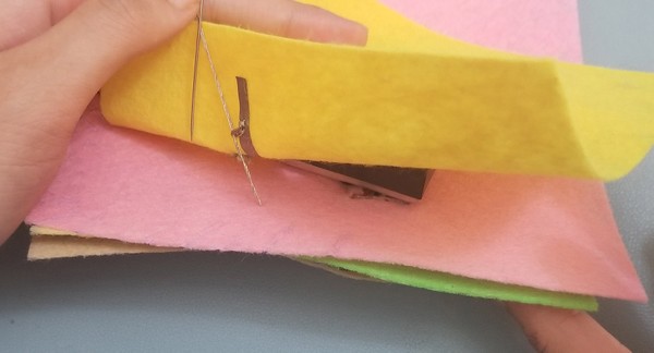
- With conductive thread, stitch down the negative '-' side of your LEDs onto the conductive fabric tape rail on the other side of the patch.
- Starting from the bottom up, thread through the '-' pin on the TinyLily that is not used up to the conductive fabric tape rail on the bottom of the LED patch. The thread should go through all the patches.
- Sew the positive ends of the LED to their respective pins.
- '+' of green LED to pin 2 of TinyLily.
- '+' of yellow LED to pin 1 of TinyLily.
- '+' of red LED to pin 0 of TinyLily.
- Re-attach the TinyLily Mini USB Adapter to the TinyLily then connect to the computer through your microUSB cable.
- Download DustRGB.ino and open it in the Arduino IDE.
- Upload the code onto your TinyLily.
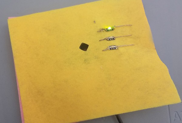
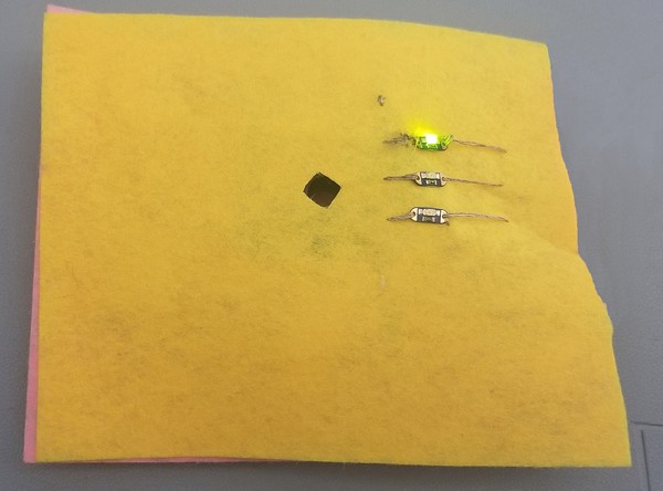
- Once your Arduino code has been successfully uploaded onto your TinyLily, open the Serial Monitor again. To test the LEDs, try throwing some dust in the air (make up from makeup brush, a sprinkle of flour, dusting your pillows, etc.). You should see the dust density in the air increase and the sensor light yellow or red.
- When your dust density is less than 0.12 mg/m3, the light should be green.
- When your dust density is less or equal to than 0.35 mg/m3 but more than 0.12 mg/m3, the light should be yellow.
- When your dust density is greater than 0.35 mg/m3, the light should be red.
- When exposed to high dust densities (>0.35 mg/m3), the program sets a 15-minute timer. The red light will start blinking as a warning if levels have remained high for 15 minutes. When exposed to medium dangerous air pollution levels, the dust sensor sets a 30-minute timer. When the sensor measures exposure to this air for more than 30 minutes, the yellow light will start rapidly blinking. The blinking will not stop until you reach safe air.
- Switch your USB adapter with your battery adapter and power the TinyLily with the LiPo battery.
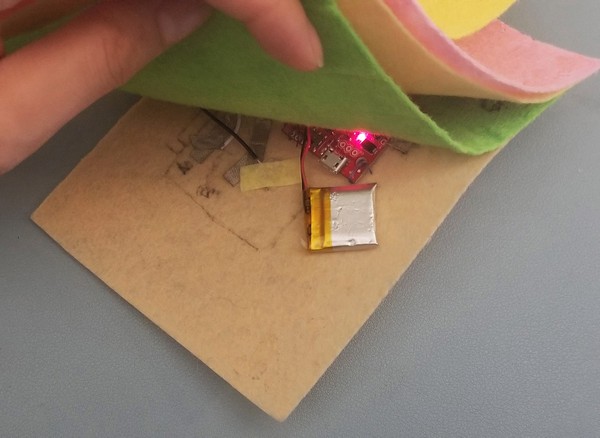
- To finalize your wearable, place the cover-up patch onto the bottom of your base patch. Stitch the patches of fabric together along the edge or hot glue the edges down. Leave one edge open for easy access to the LiPo battery.
- You can stitch this onto an existing shirt, make a necklace, put it onto a hoodie, etc. Have fun!
- Select your GND patch. This is where your negative wire will go from your base patch. Cut a 1-2 inch strip of conductive fabric tape. Tape it on the GND patch directly above your '-' output on your booster board as a horizontal rail.
/-/https/www.sciencebuddies.org/cdn/Files/18906/7/booster-removal.jpg)
/-/https/www.sciencebuddies.org/cdn/Files/18907/7/felt-layers.jpg)
/-/https/www.sciencebuddies.org/cdn/Files/18908/7/base-layer-dust-sensor.jpg)
/-/https/www.sciencebuddies.org/cdn/Files/18909/7/base-sew-dust-sensor.jpg)
/-/https/www.sciencebuddies.org/cdn/Files/18910/7/base-back-sew-dust-sensor.jpg)
/-/https/www.sciencebuddies.org/cdn/Files/18938/7/base-front-dust-sensor.jpg)
/-/https/www.sciencebuddies.org/cdn/Files/18939/7/base-back-dust-sensor.jpg)
/-/https/www.sciencebuddies.org/cdn/Files/18911/7/AO3-dust-sensor.jpg)
/-/https/www.sciencebuddies.org/cdn/Files/18912/7/dust-sensor-rectangle-drawn.jpg)
/-/https/www.sciencebuddies.org/cdn/Files/18913/7/dust-wire-sensor.jpg)
/-/https/www.sciencebuddies.org/cdn/Files/18914/7/Vcc-rail-vertical.jpg)
/-/https/www.sciencebuddies.org/cdn/Files/18915/7/VCC-rail-patch-base.png)
/-/https/www.sciencebuddies.org/cdn/Files/18916/7/Gnd-rail-horizontal.jpg)
/-/https/www.sciencebuddies.org/cdn/Files/18917/7/Gnd-rail-base-patch.png)
/-/https/www.sciencebuddies.org/cdn/Files/18918/7/GndtoBase-stitching.jpg)
/-/https/www.sciencebuddies.org/cdn/Files/18919/7/Cap-GND.jpg)
/-/https/www.sciencebuddies.org/cdn/Files/18920/7/Vcc-Cap.jpg)
/-/https/www.sciencebuddies.org/cdn/Files/18921/7/cap-dust-sensor.jpg)
/-/https/www.sciencebuddies.org/cdn/Files/18922/7/VCC-thread.jpg)
/-/https/www.sciencebuddies.org/cdn/Files/18923/7/resistor-VCC.jpg)
/-/https/www.sciencebuddies.org/cdn/Files/18924/7/dust-sensor-wire-diagram.jpg)
/-/https/www.sciencebuddies.org/cdn/Files/18925/7/A03-wiring.jpg)
/-/https/www.sciencebuddies.org/cdn/Files/18926/7/wire-GND-patch.jpg)
/-/https/www.sciencebuddies.org/cdn/Files/18927/7/VCC-wiring.jpg)
/-/https/www.sciencebuddies.org/cdn/Files/18928/7/capacitor-hole-dust-sensor.jpg)
/-/https/www.sciencebuddies.org/cdn/Files/18929/7/micro-USB-dust-sensor.jpg)
/-/https/www.sciencebuddies.org/cdn/Files/18717/5/ArduinoIDE-screenshot.jpg)
/-/https/www.sciencebuddies.org/cdn/Files/18930/7/arduino-upload-button.jpg)
/-/https/www.sciencebuddies.org/cdn/Files/18931/7/baud-menu.png)
/-/https/www.sciencebuddies.org/cdn/Files/18932/7/test-dust-sensor.jpg)
/-/https/www.sciencebuddies.org/cdn/Files/18933/7/serial-monitor-for-dust.png)
/-/https/www.sciencebuddies.org/cdn/Files/18934/7/dust-hole.jpg)
/-/https/www.sciencebuddies.org/cdn/Files/18935/7/LED-rail.jpg)
/-/https/www.sciencebuddies.org/cdn/Files/18936/7/RGB-placement-dust-sensor.jpg)
/-/https/www.sciencebuddies.org/cdn/Files/18941/7/RGB-negative-dust-sensor.jpg)
/-/https/www.sciencebuddies.org/cdn/Files/18942/7/LED-rail-stitch.jpg)
/-/https/www.sciencebuddies.org/cdn/Files/18943/7/LED-wired-dust-sensor.jpg)
/-/https/www.sciencebuddies.org/cdn/Files/18944/7/green-LED-test-dust-sensor.jpg)
/-/https/www.sciencebuddies.org/cdn/Files/18945/7/red-LED-test-dust-sensor.jpg)
/-/https/www.sciencebuddies.org/cdn/Files/18946/8/battery-placement-dust-sensor.jpg)
/-/https/www.sciencebuddies.org/cdn/Files/18947/7/base-glue-dust-sensor.jpg)
/-/https/www.sciencebuddies.org/cdn/Files/18948/7/final-dust-sensor-green-light.jpg)
Cleanup
What Happened?
In this activity, you were able to measure dust density values from a dust sensor. To make the dust sensor wearable more compact, you stacked many layers of felt on top of different kinds of conductive threads, conductive fabric tapes, and wires. This worked because felt is an insulator and does not allow electrical charge to flow between the layers.
Additionally, the dust density is measured by your sensor by shining a tiny laser into the air and measuring how cloudy the laser is from the other side. It is like how you can see dust particles indoors in the sunlight.
/-/https/www.sciencebuddies.org/cdn/Files/18949/7/dust-sunlight-door.jpg)
Digging Deeper
Air pollution is measured with many different variables and can be composed of many different particles. This can mean any chemical, physical, or biological agent. The five major pollutants are ground-level ozone, particle pollution, carbon monoxide, sulfur dioxide, and nitrogen dioxide. In this project, you observed particle pollution which is how much dust and other particulates are in the air. The longer you are exposed to bad air, the more dangerous it becomes for you. This exposure can lead to severe illnesses in the future.
Wearable devices allow for people to regulate their health and know how the current environment affects their body. This is the reason why it is very common to find wearable devices in the hospital. By using wearable devices, doctors can regulate many different patients at once and be notified when the patient is in danger.
Ask an Expert
For Further Exploration
- What other sensors can you implement into a wearable device?
- Can you add other ways to notify someone of bad air? How about a speaker? What about vibrations?
- What about aesthetic changes to your patch? Can you try making a heart shaped patch? What about a star?
/-/https/www.sciencebuddies.org/cdn/Files/20680/7/blobid1723565203039.jpg)
/-/https/www.sciencebuddies.org/cdn/Files/12222/4/smoke-pollution-environment-steam.jpg)
/-/https/www.sciencebuddies.org/cdn/Files/18709/6/unicorn-horn-finished.jpg)
/-/https/careerdiscovery.sciencebuddies.org/cdn/Files/19459/5/technician-repairing-operating-microscope.jpg)
/-/https/careerdiscovery.sciencebuddies.org/cdn/Files/20156/6/quality-control-inspector-worker.jpg)
/-/https/img.youtube.com/vi/wkbIZ9NgC3o/0.jpg)
/-/https/img.youtube.com/vi/gCBo4t8inAQ/0.jpg)
/-/https/img.youtube.com/vi/bj0fVIqGAds/0.jpg)