Summary

If you want a Project Idea with full instructions, please pick one without an asterisk (*) at the end of the title.
Abstract
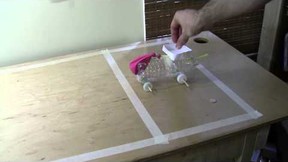
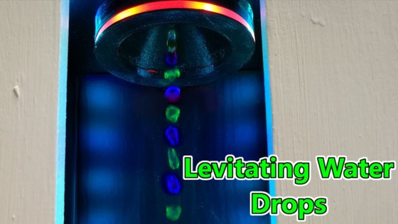
The Science Buddies project Build a Levitating Water Fountain with the Stroboscopic Effect shows you how to illuminate a dripping stream of water with a strobe light to make it look like the drops are hovering in mid-air. If you have not already, read the background section of that project and watch the following two videos. Make sure you understand frequency, period, and duty cycle before you proceed with this project.
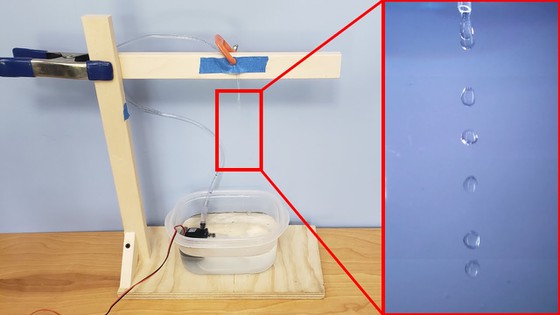
The project has you use a strobe light app on your phone. The advantage of doing this is that the app lets you easily control the frequency and duty cycle of the strobe. The disadvantage is that your phone only has a single LED, which is not very bright compared to a strobe light with many LEDs.
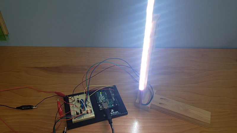
You can build your own much brighter strobe light using an Arduino™ and an LED strip. This setup will work better to demonstrate the levitating water illusion, especially if you want to film it. The challenge is that you will need to write your own program to control the frequency and duty cycle of the strobe light. This can be trickier than it seems at first. This project will guide you through the process of connecting an LED strip to an Arduino and writing a program to control it. Note that you can purchase an Arduino starter kit like the Science Buddies Electronics Kit for Arduino that will contain many of the parts you need, but you will need to purchase the LED strip separately.
There are many different types of LED strips available. The video at the beginning of this project demonstrates an analog RGB LED strip, which has separate red, green, and blue LEDs that can be combined to make different colors. The LED strip requires more power than your Arduino's pins can provide directly, so you control it with a type of transistor called a MOSFET and an external 12 volt (V) power supply (Figure 1). When the digital output pin from the Arduino goes high, the MOSFET will switch on, allowing current to flow through the LED strip. When the Arduino's output pin goes low, the LED strip will turn off.
Note that Figure 1 shows the wires for the red, green, and blue LEDs all connected to the same row on the breadboard. This means that all the LEDs will turn on at once, generating white light. If you wanted to control the colors independently, you would need three separate MOSFETs. See the reference from Adafruit in the Bibliography to learn more about the LED strips.
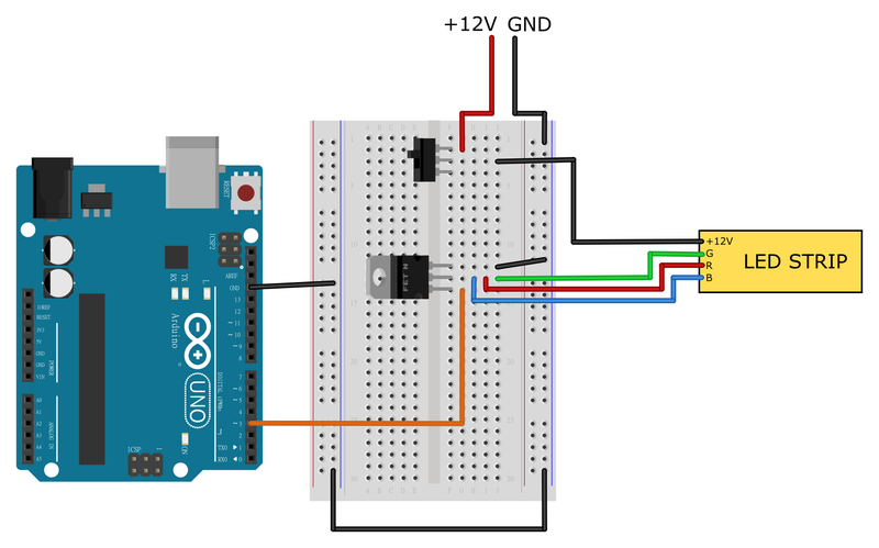 Image Credit: Ben Finio, Science Buddies / Science Buddies
Diagram showing an Arduino next to a breadboard. The breadboard contains an N-channel MOSFET and an SPDT slide switch. The MOSFET's gate is connected to Arduino pin 3 and its source pin is connected to ground. The drain is connected to the red, green, and blue pins of an RGB LED strip. The RGB LED strip's +12V pin is connected to an external 12V power supply through the switch on the breadboard. All components have a common ground.
Figure 1. Breadboard diagram showing how to connect the RGB LED strip with an Arduino and an N-channel MOSFET.
To flash the strobe light, you need to turn the Arduino's output pin on and off for specified amounts of time. Remember that a strobe light's frequency is the number of flashes per second, measured in hertz (Hz). The period is the amount of time between the beginning of one flash and the beginning of the next flash, measured in seconds. If you specify the frequency, you can calculate the period as one divided by the frequency:
Equation 1:
or, if you specify the period, you can calculate the frequency as one divided by the period:
Equation 2:
The duty cycle is the percentage of each period that the strobe light is on. Duty cycle is written as a percentage between 0 and 100 or as a decimal between 0 and 1. The amount of time the strobe light is on for each period is the duty cycle times the period:
Equation 3:
And the amount of time the strobe is off can be written as one minus the duty cycle, times the period:
Equation 4:
You can also write that the period is the sum of the on time and the off time:
Equation 5:
So, when writing an Arduino program to control your strobe light, you can specify some of the variables (for example, a target frequency or period) and use equations 1–5 to calculate the other variables as needed.
One very simple way to control the strobe is to specify your desired on time and off time, then use the delay command, which causes a delay in an integer number of milliseconds (ms), as shown in this program.
// Program #1: simple strobe control using delays in milliseconds

// enter your desired on time and off time in milliseconds
int on_time = 1;
int off_time = 19;

void setup() {
  // put your setup code here, to run once:
  pinMode(3,OUTPUT);  // set control pin as output
}

void loop() {
  // put your main code here, to run repeatedly:
  digitalWrite(3,HIGH); // turn the LEDs on
  delay(on_time);       // wait for on_time milliseconds
  digitalWrite(3,LOW);  // turn the LEDs off
  delay(off_time);      // wait for off_time milliseconds
}
In this case, with an on time of 1 ms and an off time of 19 ms, that gives a period of 20 ms (Equation 5) and a frequency of 50 Hz (Equation 2). Technically, the digitalWrite command also takes a small amount of time, and it takes time for the Arduino to go back to the beginning of the loop function, but these delays are very small (measured in nanoseconds, not milliseconds), so they do not have a big effect on the actual output frequency.
However, note that the delay function takes the unsigned long data format as an input. That means you cannot use a value with a decimal—the input must be an integer. This only lets you create delays with a 1 ms resolution. So, for example, you cannot use the code above to generate a frequency of exactly 51 Hz, because that would require a period of 1/51 = 0.01960784314 sec, or about 19.6 ms (Equation 1). If you increase the off time to 20 ms, resulting in a period of 21 ms, the new frequency will be 1/0.021 = 47.619 Hz. So, while program #1 is very simple, it does not work very well for making fine adjustments to the frequency. Ideally, you want to be able to adjust the frequency in increments of 1 Hz or even less. It is also more intuitive if you can specify the frequency instead of specifying the on time and off time directly.
You can get more fine-tuned control of the delays by using the delayMicroseconds function instead. This function causes a delay in microseconds (μs) instead of milliseconds. However, delayMicroseconds only works for input values up to 16,383, or 16.383 ms. To get delays longer than 16,383 μs, you need to use multiple delayMicroseconds commands in sequence. The following program lets you enter a desired frequency and duty cycle, then calculates the required delays in microseconds. Note that this program uses the float data type, which allows you to enter numbers with decimals for the frequency and duty cycle.
// Program #2: strobe control using specified frequency and duty cycle with
// automatically calculated delays in microseconds

// enter your desired frequency and duty cycle
float frequency = 50;        // frequency in Hz
float duty_cycle = 0.1;      // duty cycle (must be between 0-1)

// declare variables that will be calculated by the program
unsigned long period_us;     // period in microseconds
unsigned long on_time_us;    // on time in microseconds
unsigned long off_time_us;   // off time in microseconds
unsigned long on_time_us_4;  // 1/4 of the on time
unsigned long off_time_us_4; // 1/4 off the off time
// (required because the delayMicroseconds command only
// works with values up to 16,383, so we will use four
// delayMicroseconds commands in a row to get longer delays

void setup() {
  // put your setup code here, to run once:
  pinMode(3,OUTPUT);                    // set control pin as output
  period_us = 1e6/frequency;            // calculate period in microseconds
  on_time_us = duty_cycle*period_us;    // calculate on time in microseconds
  off_time_us = period_us - on_time_us; // calculate off time in microseconds
  on_time_us_4 = on_time_us/4;          // divide on time by 4
  off_time_us_4 = off_time_us/4;        // divide off time by 4
}

void loop() {
  // put your main code here, to run repeatedly:
  digitalWrite(3,HIGH);  // turn output pin on
  // wait for a total of on_time_us microseconds using four delays
  delayMicroseconds(on_time_us_4);
  delayMicroseconds(on_time_us_4);
  delayMicroseconds(on_time_us_4);
  delayMicroseconds(on_time_us_4);
  digitalWrite(3,LOW);  // turn output pin off
  // wait for a total of off_time_us microseconds using four delays
  delayMicroseconds(off_time_us_4);
  delayMicroseconds(off_time_us_4);
  delayMicroseconds(off_time_us_4);
  delayMicroseconds(off_time_us_4);
}
Program #2 works much better for accurate control of the frequency and duty cycle. However, it is somewhat inconvenient because you need to re-upload the program to your Arduino any time you want to change one of the values. It is more convenient to connect potentiometers to your Arduino's analog input pins and use the analogRead function. This will allow you to turn the knobs to adjust the frequency and duty cycle while your program is running. Many tutorials for using potentiometers and the analogRead function with an Arduino are available online (see bibliography). Figure 2 shows an example circuit.
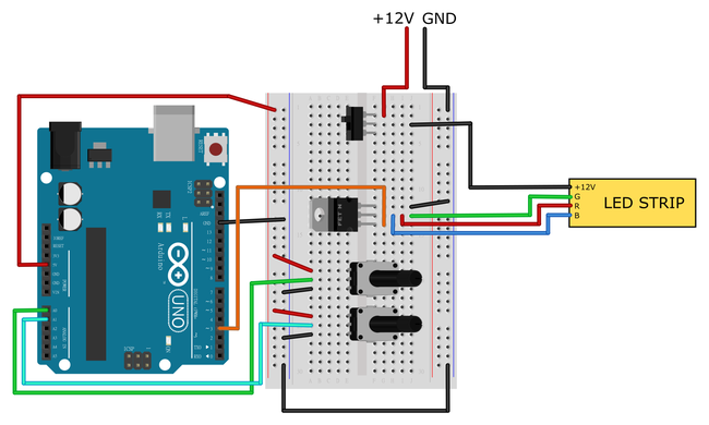 Image Credit: Ben Finio, Science Buddies / Science Buddies
Each potentiometer has three pins. The outer two pins are connected to 5V and GND. The middle pin of one potentiometer is connected to analog pin A0 and the middle pin of the other potentiometer is connected to analog pin A2.
Figure 2. Breadboard diagram showing two potentiometers connected to the Arduino's analog input pins.
The following program reads the analog pin values using the analogRead function, then converts them to frequency and duty cycle using the map function (note that map uses integer math, so in this program the duty cycle is defined as a percentage between 0 and 100 instead of a decimal between 0 and 1).
// Program #3: strobe control using potentiometers and analog inputs
// to adjust frequency and duty cycle

int frequency;        // frequency in Hz
int duty_cycle;       // duty cycle (between 1-100
int analog1;          // analog pin 1 reading
int analog2;          // analog pin 2 reading
unsigned long period_us;     // period in microseconds
unsigned long on_time_us;    // on time in microseconds
unsigned long off_time_us;   // off time in microseconds
unsigned long on_time_us_4;  // 1/4 of the on time
unsigned long off_time_us_4; // 1/4 off the off time
// (required because the delayMicroseconds command only
// works with values up to 16,383, so we will use four
// delayMicroseconds commands in a row to get longer delays

void setup() {
  // put your setup code here, to run once:
  pinMode(3,OUTPUT);                    // set control pin as output
}

void loop() {
  // put your main code here, to run repeatedly:
  // read analog pins
  analog1 = analogRead(A1);
  analog2 = analogRead(A2);

  // convert analog values to frequency and duty cycle using the map function
  // note that analogRead returns a value between 0-1023
  // we want to map this to desired min and max values for the frequency and duty cycle
  frequency = map(analog1,0,1023,1,100);
  duty_cycle = map(analog2,0,1023,1,100);

  // calculate period, on time, and off time in microseconds
  period_us = 1e6/frequency;
  on_time_us = duty_cycle*period_us/100;
  off_time_us = period_us - on_time_us;

  // divide on and off times by 4 for use in delays
  on_time_us_4 = on_time_us/4;
  off_time_us_4 = off_time_us/4;

  digitalWrite(3,HIGH);  // turn output pin on
  // wait for a total of on_time_us microseconds using four delays
  delayMicroseconds(on_time_us_4);
  delayMicroseconds(on_time_us_4);
  delayMicroseconds(on_time_us_4);
  delayMicroseconds(on_time_us_4);
  digitalWrite(3,LOW);  // turn output pin off
  // wait for a total of off_time_us microseconds using four delays
  delayMicroseconds(off_time_us_4);
  delayMicroseconds(off_time_us_4);
  delayMicroseconds(off_time_us_4);
  delayMicroseconds(off_time_us_4);
}
However there is a small catch with this approach. The analogRead command is rather slow (at least as far as a microcontroller is concerned) and takes about 100 μs to run. So, adding analogRead commands inside your loop function will cause additional delays, slowing your loop down. For example, even when one potentiometer is turned all the way up and the frequency is set to 100 Hz, the actual frequency of the signal (as measured at the output pin by an oscilloscope) is only 95 Hz. For the same reason, you need to be careful about adding Serial.print commands for debugging. Adding a single Serial.print command to the loop in program #3 drops the actual output frequency down to 93 Hz when the calculated frequency is 100 Hz.
Programs 1, 2, and 3 all present different ways to control an LED strip with an Arduino. You can decide how complex you want your program to be, and if you want to add even more features.
There are even more things for you to adjust. The background color behind your levitating water fountain and the physical location of the LED strips (e.g., in front of, to the side of, or above the dripping water) will have an impact on its appearance. Can you figure out how to make your own Arduino strobe light to add amazing effects to your levitating water fountain?
For some additional inspiration, check out these videos by Isaac Chasteau:

Bibliography
- Arduino (n.d.). Language Reference. Retrieved June 17, 2022.
- Lady Ada (2012, Nov. 26). RGB LED Strips. Retrieved June 17, 2022.
- Arduino (2022, May 23). Read Analog Voltage. Retrieved June 17, 2022.
Ask an Expert
Global Connections
The United Nations Sustainable Development Goals (UNSDGs) are a blueprint to achieve a better and more sustainable future for all.

Careers
If you like this project, you might enjoy exploring these related careers:

Contact Us
If you have purchased a kit for this project from Science Buddies, we are pleased to answer your questions.In your email, please follow these instructions:
- What is your Science Buddies kit order number?
- Please describe how you need help as thoroughly as possible:
Examples
Good Question I'm trying to do Experimental Procedure step #5, "Scrape the insulation from the wire. . ." How do I know when I've scraped enough?
Good Question I'm at Experimental Procedure step #7, "Move the magnet back and forth . . ." and the LED is not lighting up.
Bad Question I don't understand the instructions. Help!
Good Question I am purchasing my materials. Can I substitute a 1N34 diode for the 1N25 diode called for in the material list?
Bad Question Can I use a different part?
Contact Us
Related Links
- Science Fair Project Guide
- Other Ideas Like This
- Electricity & Electronics Project Ideas
- My Favorites