Abstract
How easy is it for you to walk along and follow a line that is painted on the ground? Simple, right? You might be able to follow a line without giving it much thought, but how could a robot do that? In this project, you will build your own automatic line-following robot that can race around a track that you create. This technology has plenty of real-world applications—maybe one day you could help design self-driving cars!
Summary
You will need to know how to use a breadboard to do this project. See the Science Buddies reference How to Use a Breadboard for Electronics and Circuits if you have not used a breadboard before.
A kit is available from our partner Home Science Tools®. See the Materials section for details.
Short circuits can get very hot and present a burn hazard. Be careful to follow the directions in the Procedure in order to avoid short circuits when building your robot.
Ben Finio, PhD, Science Buddies
Circuit design by Howard Eglowstein, Science Buddies
- LEGO is a registered trademark of The LEGO Group.
- K'NEX is a registered trademark of K'NEX Limited Partnership Group.
/-/https/i.ytimg.com/vi/-cilOho6l3Q/maxresdefault.jpg)
Objective
Build a line-following robot and make adjustments so it can follow a line on the floor without going off-course.
Introduction
Have you ever walked along a line painted on the ground at a playground? Or have you ridden your bike along a trail, or ridden along a road in a car, with an adult driving? All of these things might seem pretty easy to do—you hardly have to think about them at all (although if you are going too fast or not paying attention, you might go off the trail or crash your bike!). How can you make a robot automatically follow a trail? There are many types of automatic, line-following or self-driving robots, ranging from the simple one you will build in this project (which follows a black line on a white floor), to completely automatic self-driving cars that can handle much more complex tasks, like stopping at red lights and avoiding other cars. These more-advanced cars and robots use sensors, like cameras, to observe the world around them and know how to react—just like you use your eyes (or a visually impaired person would use a cane and their sense of touch) to observe a trail or path in front of you. The robot you build in this project will use two sensors and a simple circuit that allows it to steer left and right to follow a line. Figure 1 shows what the robot will look like, and this video shows a demonstration of how it works.
/-/https/www.sciencebuddies.org/cdn/Files/6309/18/line-following-robot.jpg)
Figure 1. The line-following robot that you will build in this project.
So, how is the robot able to automatically track a dark line? The robot relies on a sensor that detects infrared (IR) light (which is part of the electromagnetic spectrum, just outside the range of visible light that humans can see). The sensor consists of two parts: an IR emitter which sends out IR light, and an IR detector, which detects incoming IR light. As shown in Figure 2, when combined, these two parts can be used to detect a nearby bright object, like white paper. The IR emitter sends out IR light, which bounces back off the white paper, and is "seen" by the IR detector. If the surface is too dark, the IR light will be absorbed by the surface instead of bouncing back from it, so the IR detector will not "see" any IR light.
/-/https/www.sciencebuddies.org/cdn/Files/6310/11/infrared-light-object-sensor.png)
Figure 2. An illustration of how the IR sensors in this project work. The IR emitter emits IR light. Bright surfaces will reflect this light back toward the IR detector and trigger the sensor, while dark surfaces will not.
Now you understand how an IR sensor can be used to detect a black line, but how do you actually get a robot to drive along and follow the line? You will need to use two of the sensors, one placed on either side of the line, as shown in Figure 3. Through an electronic circuit, each sensor controls the speed of one of the robot's two wheels. When both sensors "see" white, both wheels spin at full speed, causing the robot to drive straight. When one sensor sees the black line, it causes one of the robot's wheels to slow down, which makes the robot turn so it can continue to follow the line. For example, if the left sensor "sees" black, the left wheel slows down; this causes the robot to turn left. As shown in Figure 3, this allows the robot to automatically follow a curved track!
Figure 3. An illustration of how the line-following robot steers. It uses two IR sensors to detect the line. When a sensor "sees" the dark line, the circuit slows down the wheel on that side of the robot, causing the robot to turn.
In this robotics project, you will follow step-by-step instructions to build your own line-following robot. It turns out that the position of the IR sensors has a big impact on the robot's performance. If they are too close together (or too far apart), or too close to the floor (or too far above it), the robot might have trouble following the line. It could even overshoot a curve and crash! So, you will follow the Engineering Design Process to adjust your robot's sensors. Can you get it to drive without crashing?
The rest of the Introduction contains more details about the electronic components used in the circuit. The following information is provided as a reference, and you do not need to fully understand it in order to do the project. If are ready to just start building the robot, you can move on to the Procedure.
If you would like to read the rest of the Introduction, it will help if you are familiar with basic electronics terms like voltage, current, and resistance. Science Buddies has many beginner and intermediate level electronics projects, an Electronics Primer, and an Electricity, Magnetism, & Electromagnetism Tutorial that can help you learn more about these topics. You can also refer to the Bibliography for more information.
For a complete technical explanation of how the circuit works, including a circuit diagram, see the Help section.
The circuit you will build in this project uses a variety of electronic components. All of the components are combined on a chassis, or plastic base for the robot, which includes wheels. Some of the components, like batteries and switches, you probably use every day (even if you do not notice it). Others, like diodes and transistors, might be new to you if you have not done an electronics project before. Table 1 has pictures and descriptions of each component you will use in this project. For a more detailed explanation of what each component does in the circuit, see the Help section.
| Item Name | Picture | Description |
|---|---|---|
| Battery pack | This is the power supply for your robot. Battery packs come in all shapes and sizes. The one in this project holds 4 AA batteries. | |
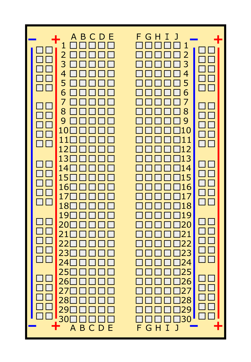
| Breadboard |
/-/https/www.sciencebuddies.org/cdn/Files/7158/11/breadboard-picture.jpg) |
A breadboard allows you to quickly and easily connect wires and electronic components in order to build a circuit. The connections are not permanent, so you can easily move things around if you make a mistake. |
| Switch | You use switches every day to turn lights and appliances on and off. This is a tiny switch that fits on a breadboard, to let you turn your robot on and off. | |
| Jumper wire |
/-/https/www.sciencebuddies.org/cdn/Files/6283/12/jumper-wires.jpg) |
Jumper wires are short wires used to make electrical connections on a breadboard. They come with many colors of plastic insulation, which makes it easy to color-code and organize complicated circuits. |
| DC Motor | Electrical current causes a motor to spin. Two motors drive the robot's wheels. This type of motor runs on direct current (DC) from a battery (as opposed to alternating current [AC] from a wall outlet). | |
| MOSFET |
/-/https/www.sciencebuddies.org/cdn/Files/7149/67/MOSFET-picture.jpg) |
A MOSFET is a special type of transistor, which acts like a control valve to let electrical current flow. As an analogy, think of how a valve can control the flow of water through a garden hose. In this circuit, the MOSFETs control the flow of current through the motors. See the Help section for more detailed information about MOSFETs, including what MOSFET stands for. |
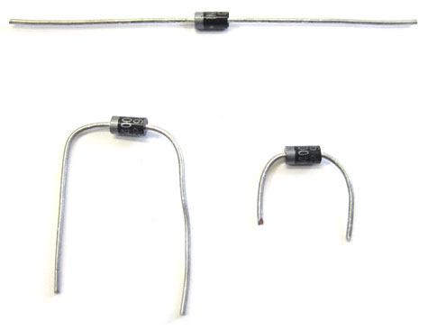
| Diode | A diode is like a one-way valve for electricity. It only lets current flow in one direction. In this circuit, diodes are used to protect the MOSFETs from voltage spikes that can be caused by abruptly stopping the motors. | |
| Male-female jumper wire |
/-/https/www.sciencebuddies.org/cdn/Files/6312/11/M-F-jumper-wires.png) |
This is a special type of jumper wire that comes with a female connector on one end and a male connector on the other end. |
| Resistor |
/-/https/www.sciencebuddies.org/cdn/Files/6313/17/resistor.jpg) |
As the name implies, a resistor resists the flow of electrical current. Electrical resistance is measured in ohms (Ω). Resistors come in many different values, marked by color-coded bands. In this project you will use 220 Ω resistors and 4.7 kΩ resistors. |
| IR sensor | The IR sensor consists of two parts, an emitter and a detector. The emitter is an IR light-emitting diode (LED), which emits IR light. The detector is an IR phototransistor, which is activated by the light. When combined, these two parts allow the sensor to detect nearby reflective objects, as shown in Figure 2. |
/-/https/www.sciencebuddies.org/cdn/Files/7144/26/spdt-switch-new.jpg)
Table 1. Pictures and descriptions of each circuit component used in this project.
How are all these components combined to control the motors and make the robot steer? While the full details are in the Help section, there are two things that will help you understand the basics of how the robot works:
- The MOSFETs act like valves that control flow of electricity through the motors. When a MOSFET's input receives a high voltage, it makes a motor turn on, which spins a wheel. When a MOSFET's input receives a low voltage, it makes the motor shut off, so the wheel stops.
- The IR sensor can be set up so it outputs a high voltage when it "sees" white, and a low voltage when it "sees" black.
Can you imagine how these two things could be set up to control a motor, and spin a wheel, based on whether or not the sensor sees a black line? You will need to connect the output of the sensor to the input of the MOSFET. Figure 4 shows a simplified diagram of this process (remember to refer to the Help section for the full explanation).
/-/https/www.sciencebuddies.org/cdn/Files/6315/11/line-following-robot-block-diagram.png)
Figure 4. A block diagram of the robot's operation (this is a simplified diagram that excludes some components; see the Help section for the actual circuit diagram).
Terms and Concepts
General robotics and electronics terms:
- Sensor
- Circuit
- Infrared (IR) light
- Electromagnetic spectrum
- IR emitter
- IR detector
- Voltage
- Current
- Resistance
- Chassis
Circuit components:
- Battery pack
- Breadboard
- Switch
- Jumper wires
- Male-female jumper wire
- DC motor
- MOSFET
- Transistor
- Diode
- Resistor
- Ohm (Ω)
- IR sensor
- Light-emitting diode (LED)
- Phototransistor
Advanced terms (see Help section)
- Base
- Collector
- Emitter
- Bipolar transistor
- Field-effect transistor
- Gain
- Gate
- Drain
- Source
- Threshold voltage
- Saturation
- N-channel MOSFET
- P-channel MOSFET
- Current-limiting resistor
- Pull-down resistor
Questions
- What real-life conditions and obstacles do self-driving cars have to deal with?
- What types of sensors do self-driving cars use to help them drive?
- How are real-world self-driving cars different from the robot you will build in this project?
- How can an IR light sensor be used to detect a dark line and help a robot follow it?
- How do you think changing the IR sensors' distance from the ground will affect the robot's steering?
- How do you think changing the horizontal distance between the IR sensors will affect the robot's steering?
Bibliography
These beginner references will be useful if you are just starting out with electronics and robotics:
- Finio, B. (2015, September 5). How to Use a Breadboard. Retrieved June 23, 2016.
- Science Buddies staff (n.d.). Electronics Primer: Introduction. Retrieved September 8, 2015.
These references will be useful for students who want to learn more about how the circuit works, and about electronics in general:
- Lindblom, J. (n.d.). How to Read a Schematic. SparkFun Electronics. Retrieved June 2, 2014.
- Taylor, C. (n.d.). Voltage, Current, Resistance, and Ohm's Law. SparkFun Electronics. Retrieved June 2, 2014.
These references contain specific information about some of the circuit components used in this project:
- Everlight (2007, April 4). Technical Data Sheet Opto Interrupter. Everlight Electronics Co., Ltd. Retrieved October 2nd, 2019.
- Storr, W. (2014, June 2). The Mosfet. Electronics Tutorials. Retrieved June 4, 2014.
- Poole, N. (n.d.). Light-Emitting Diodes (LEDs). SparkFun Electronics. Retrieved June 19, 2014.
- Lindblom, J. (n.d.). Resistors. SparkFun Electronics. Retrieved June 19, 2014.
Materials and Equipment 
Recommended Project Supplies
/-/https/www.sciencebuddies.org/cdn/Files/9118/11/bluebot-motion-activated-googly-1100_1.png)
- BlueBot: 4-in-1 Robotics Kit, available from our partner Home Science Tools®. See the Background tab for pictures if you are not sure what a part looks like. You will need these items from the kit (the kit also contains additional parts for three other projects):
- Blue plastic robot chassis (includes wheels, motors, and 4xAA battery holder)
- 3xAA battery holder (this is used in place of the 4xAA battery holder if your robot is going too fast)
- AA batteries (4)
- Breadboard
- Jumper wire kit
- Power switch
- Diodes (2)
- MOSFETs (2)
- 150 Ω resistor (2) (brown, green, brown, gold stripes)
- 220 Ω resistors (2) (red, red, brown, gold stripes)
- 4.7 kΩ resistors (2) (yellow, purple, red, gold stripes)
- IR sensors (2)
- Male-female jumper wires (8)
- You will also need to gather these items, not included in the kit:
- Small Phillips-head screwdriver
- Double-sided foam tape
- Optional: Wire cutters (can be used to shorten the metal leads on some parts of your circuit, making the circuit "neater")
- Optional: Needle-nose pliers or tweezers (make it easier to handle small circuit components)
- Popsicle sticks (2), or building toy pieces like LEGO® or K'nex® (used to attach the IR sensors to the front of your robot)
- Hot glue gun or duct tape
- Clear tape
- Flat, open floor space to make a line-following track
- White posterboard (at least 4 pieces that you can arrange in a 2x2 grid on the floor). If you have more floor space, you can make a larger track with a 3x3 or even a 4x4 grid.
- Black electrical tape or a large, black permanent marker
- Scissors
- Lab notebook
Disclaimer: Science Buddies participates in affiliate programs with Home Science Tools®, Amazon.com, Carolina Biological, and Jameco Electronics. Proceeds from the affiliate programs help support Science Buddies, a 501(c)(3) public charity, and keep our resources free for everyone. Our top priority is student learning. If you have any comments (positive or negative) related to purchases you've made for science projects from recommendations on our site, please let us know. Write to us at [email protected].
Experimental Procedure
Assembling Your BlueBot Chassis
- Follow the instructions in the video to assemble your robot chassis.
- Note that your kit does come with printed directions for assembling the chassis, but we recommend watching the video so you fully understand how all the parts fit together.
- Note that we recommend using double-sided foam tape to attach the battery holder to the top of the chassis, as shown in Figure 5. The printed directions recommend putting the battery holder in-between the two chassis plates, but this makes it harder to change the batteries.
/-/https/i.ytimg.com/vi/SBeGl_IgWwY/maxresdefault.jpg)
/-/https/www.sciencebuddies.org/cdn/Files/7136/33/bluebot-chassis-assembled.jpg)
Figure 5. A completed BlueBot chassis with breadboard and battery pack on top.
Assembling Your Circuit
- To build your circuit, you will need to know how to use a breadboard. Watch the video and see the Science Buddies reference How to Use a Breadboard for Electronics and Circuits.
/-/https/i.ytimg.com/vi/MtiJz7gh1VU/maxresdefault.jpg)
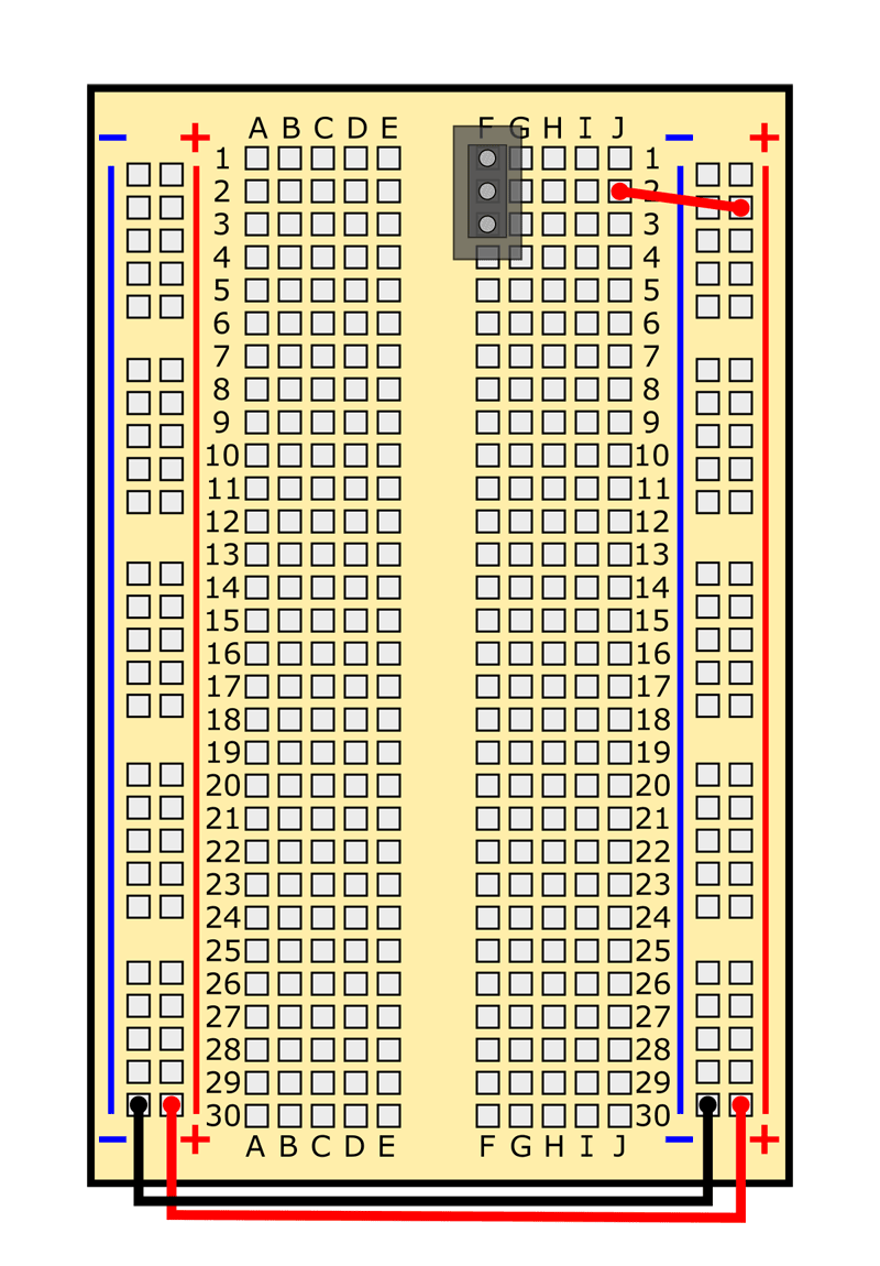
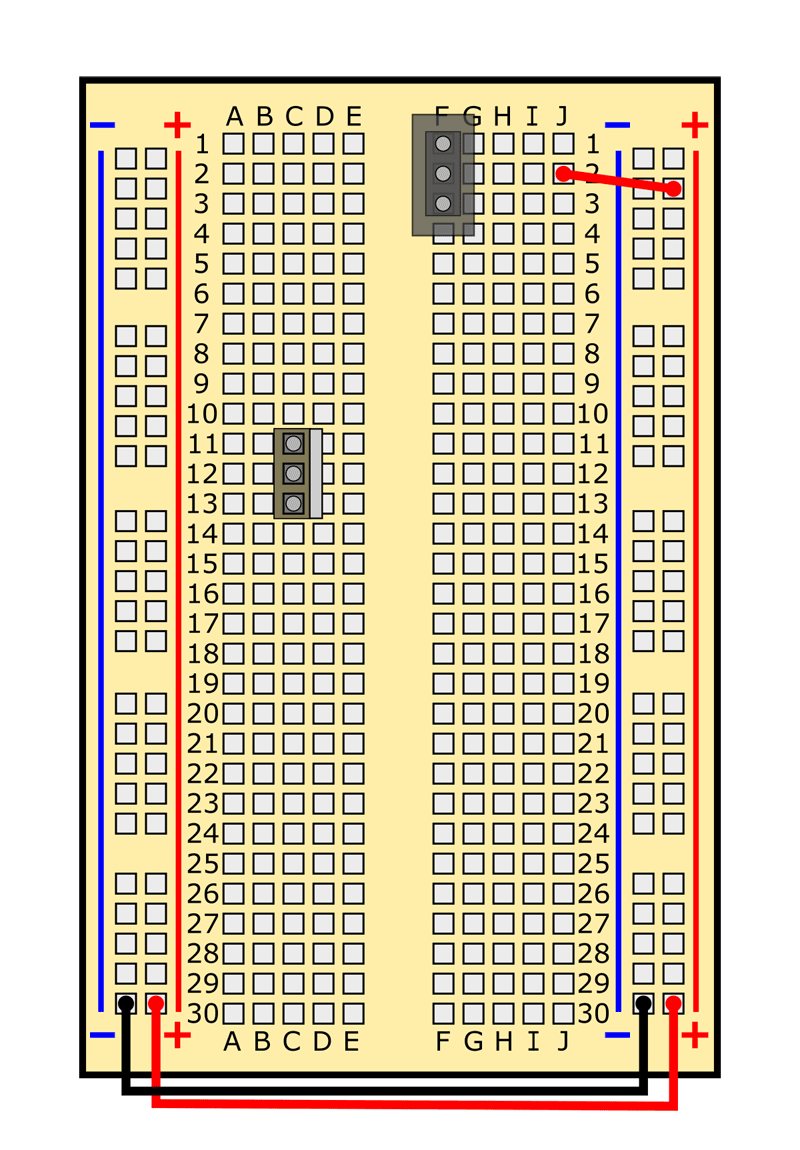
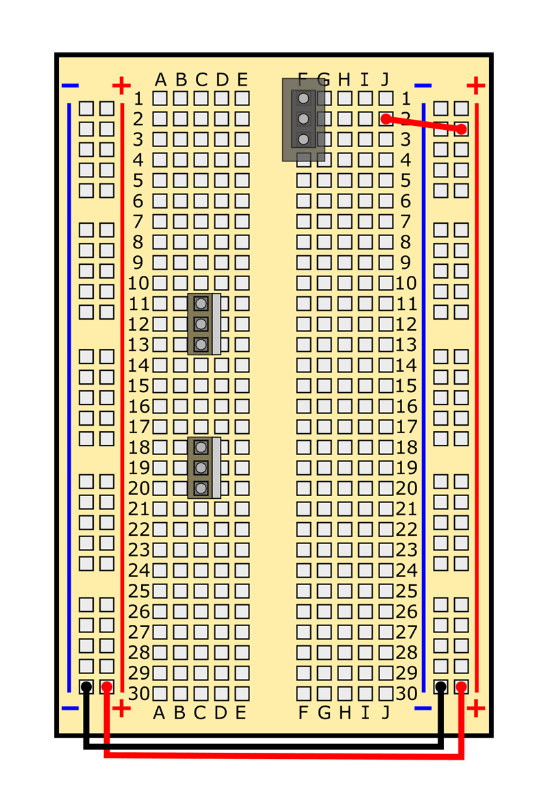
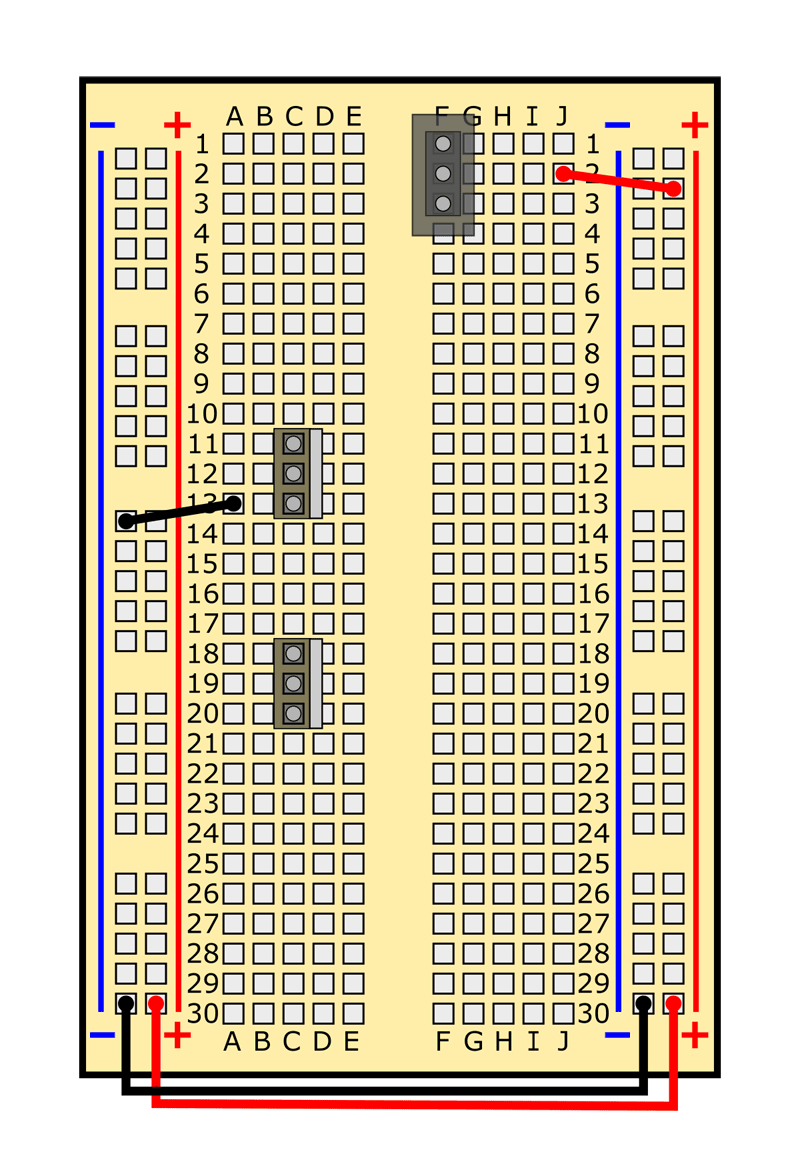
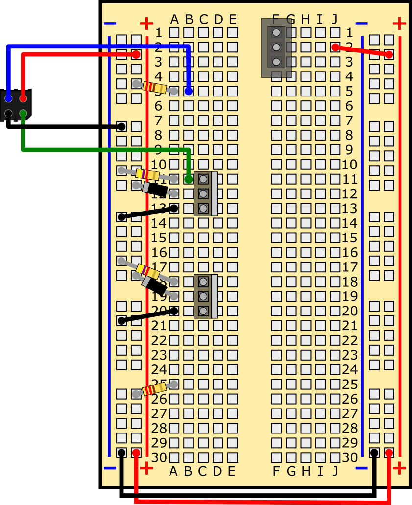
- Now that you know how to use a breadboard, you are ready to assemble your BlueBot circuit. Table 2 shows a list of all the components in the circuit and where they go on the breadboard. You can download and print a PDF of this table—complete with checkboxes to track each step—to use while you are building your robot. You can also view a slideshow that shows breadboard diagrams of the circuit. Follow along in the table and/or slideshow to build your circuit one component at a time. Your finished circuit should look like the one in Figure 6. Pay attention to these notes:
- Remember to push all components firmly into the breadboard.
- All references to orientation (up, down, left, and right) assume you have the breadboard "right-side up," so the writing is facing you.
- Your jumper wire kit comes with an assortment of colors, and the colors may vary. It does not matter what color jumper wires you use. Your colors do not need to match the colors in the diagrams.
- You will use male-female jumper wires to connect the IR sensors to the breadboard. These wires act like "extension cords" that allow you to attach the sensors to the front of your robot, so they can look down at the ground in front of the robot. You do need to keep track of the wire colors when connecting the IR sensors, since you need to connect the four pins in the right order.
- Insert the batteries last. If you see or smell smoke when you insert the batteries, you have a short circuit somewhere. Immediately remove the batteries and recheck your wiring.
| Component | Picture | Symbol | Breadboard holes | Note |
|---|---|---|---|---|
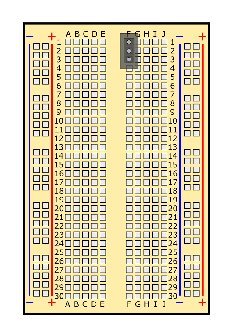
| Power switch | F1, F2, F3 | Direction in which it is facing does not matter, but make sure to slide switch down (toward row 30, away from row 1), this is the "off" position. | ||
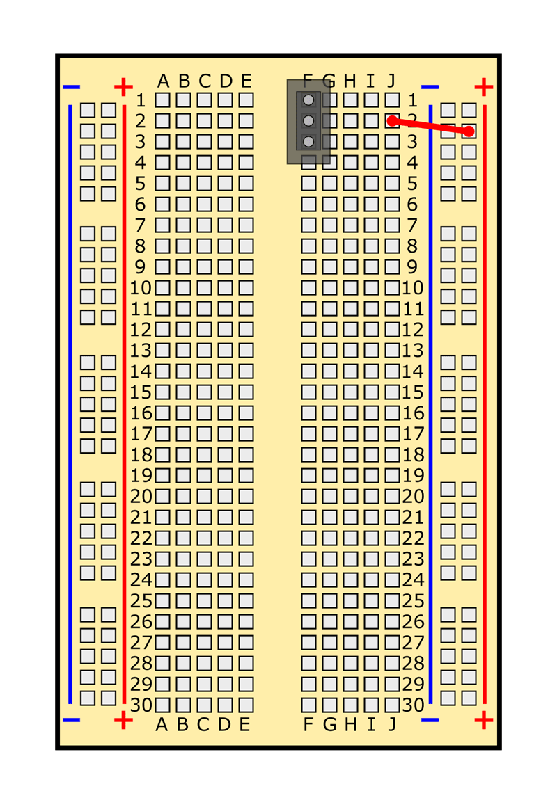
| Jumper wire | J2 to (+) bus | Color does not matter. | ||
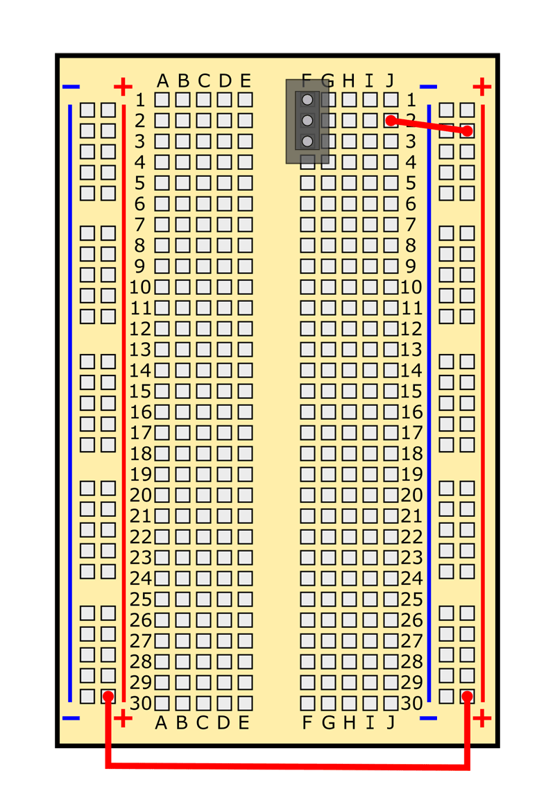
| Jumper wire | Left side (+) bus to right side (+) bus | Color does not matter. | ||
| Jumper wire | /-/https/www.sciencebuddies.org/cdn/Files/7145/12/jumper-wire-picture.jpg) |
/-/https/www.sciencebuddies.org/cdn/Files/7146/11/jumper-wire-symbol.png) |
Left side (-) bus to right side (-) bus | Color does not matter. |
| MOSFET | |
/-/https/www.sciencebuddies.org/cdn/Files/6296/26/breadboard-mosfet.jpg) |
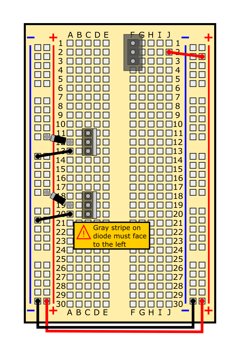
C11, C12, C13 | Writing should face to the left, large silver tab should face to the right. Note: the writing on your MOSFET might not match the picture exactly. This is OK. |
| MOSFET | |
|
C18, C19, C20 | Writing should face to the left, large silver tab should face to the right. Note: the writing on your MOSFET might not match the picture exactly. This is OK. |
| Jumper wire | |
|
A13 to (-) bus | Color does not matter. |
| Jumper wire | |
|
A20 to (-) bus | Color does not matter. |
| Diode | /-/https/www.sciencebuddies.org/cdn/Files/7151/70/diode-picture.jpg) |
/-/https/www.sciencebuddies.org/cdn/Files/6295/26/breadboard-diode.jpg) |
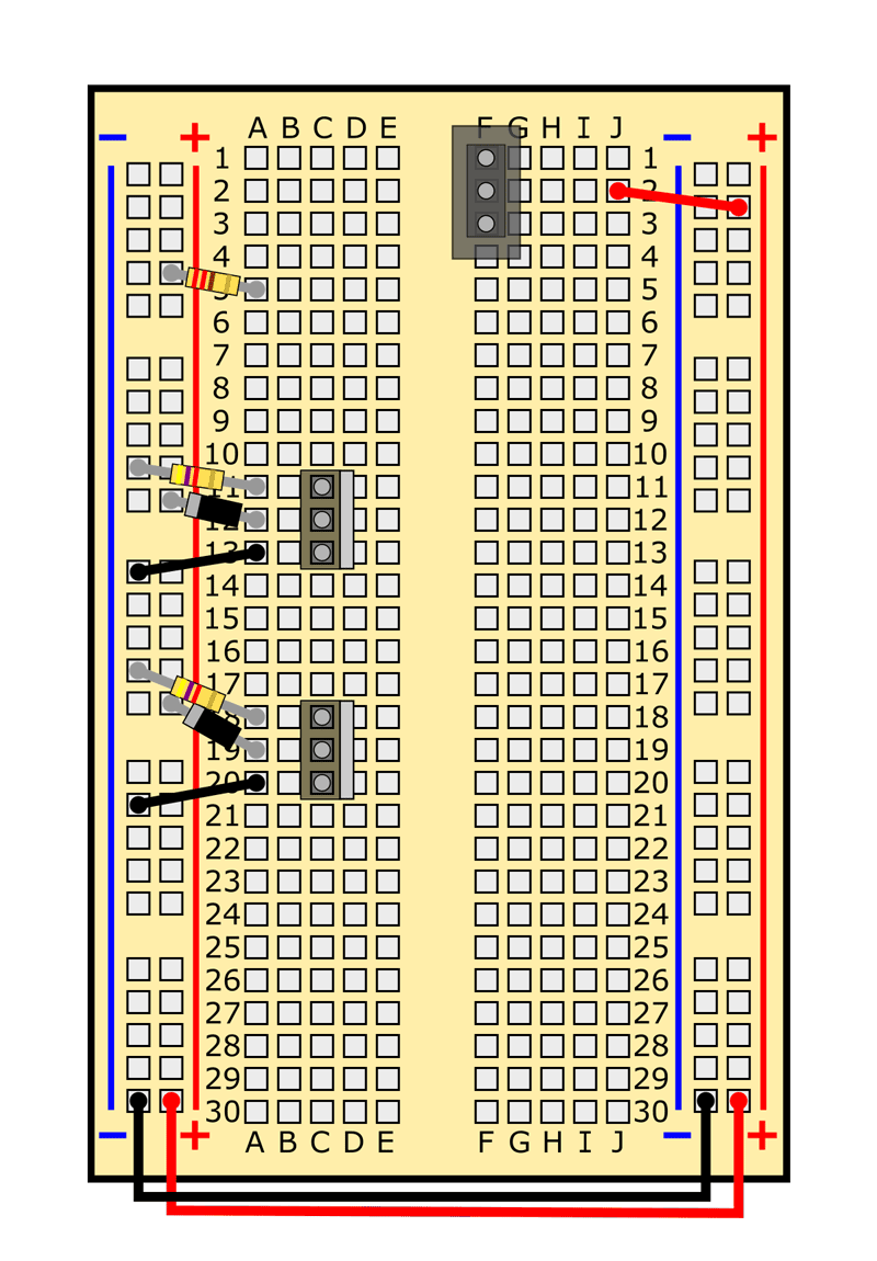
A12 to (+) bus | Gray band must face to the left. Optional: Shorten the leads. |
| Diode | |
|
A19 to (+) bus | Gray band must face to the left. Optional: Shorten the leads. |
| 4.7k Ω resistor | /-/https/www.sciencebuddies.org/cdn/Files/7219/11/47k-resistor-picture.jpg) |
/-/https/www.sciencebuddies.org/cdn/Files/7218/11/47k-resistor-symbol.png) |
A11 to (-) bus | Direction does not matter. Make sure you pick the right color bands! (yellow, purple, red, gold) |
| 4.7k Ω resistor | |
|
A18 to (-) bus | Direction does not matter. Make sure you pick the right color bands! (yellow, purple, red, gold) |
| 220 Ω resistor | /-/https/www.sciencebuddies.org/cdn/Files/7220/16/220-resistor-picture.jpg) |
/-/https/www.sciencebuddies.org/cdn/Files/7221/10/220-resistor.png) |
A5 to (+) bus | Direction does not matter. Make sure you pick the right color bands! (red, red, brown, gold) |
| 220 Ω resistor | |
|
A25 to (+) bus | Direction does not matter. Make sure you pick the right color bands! (red, red, brown, gold) |
| Top IR sensor | /-/https/www.sciencebuddies.org/cdn/Files/6314/26/IR-sensor.jpg) |
/-/https/www.sciencebuddies.org/cdn/Files/6336/18/IR-sensor-symbol.png) |
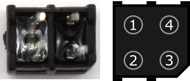
Black wire to (-) bus Red wire to (+) bus Blue wire to B5 Green wire to B11 |
There is a small notch in one corner of the black plastic case. Place notch in bottom right with pins facing you. Counter-clockwise from the top left, connect blue, black, green, and red wires. |
| Bottom IR sensor | |
|
Black wire to (-) bus Red wire to (+) bus Blue wire to B25 Green wire to B18 |
There is a small notch in one corner of the black plastic case. Place notch in bottom right with pins facing you. Counter-clockwise from the top left, connect blue, black, green, and red wires. |
| Top motor | /-/https/www.sciencebuddies.org/cdn/Files/7152/72/DC-motor-picture.jpg) |
/-/https/www.sciencebuddies.org/cdn/Files/7153/25/motor-symbol.png) |
Red lead to (+) bus Black lead to E12 |
When the robot is driving forward, this is the "right" motor. |
| Bottom motor | |
|
Red lead to (+) bus Black lead to E19 |
When the robot is driving forward, this is the "left" motor. |
| Battery holder | /-/https/www.sciencebuddies.org/cdn/Files/7154/72/4xAA-battery-holder-picture.jpg) |
/-/https/www.sciencebuddies.org/cdn/Files/7155/10/battery-holder-symbol.png) |
Red lead to J1 Black lead to (-) bus |
Do not insert batteries until circuit is complete. |
| AA battery | /-/https/www.sciencebuddies.org/cdn/Files/7156/25/AA-battery-picture.jpg) |
/-/https/www.sciencebuddies.org/cdn/Files/7157/25/battery-symbol.png) |
N/A | Insert into battery holder. Make sure (+) signs on batteries line up with (+) signs in battery holder. |
/-/https/www.sciencebuddies.org/cdn/Files/7143/12/switch-symbol.png)
Table 2. List of circuit components and locations. A printable PDF version is available.
/-/https/www.sciencebuddies.org/cdn/Files/7163/23/line-following-slide23.png)
/-/https/www.sciencebuddies.org/cdn/Files/7208/14/line-following-slide-11.png)
/-/https/www.sciencebuddies.org/cdn/Files/7209/14/line-following-slide-12.png)
/-/https/www.sciencebuddies.org/cdn/Files/7214/21/line-slide19.png)
/-/https/www.sciencebuddies.org/cdn/Files/7215/24/line-slide20.png)
/-/https/www.sciencebuddies.org/cdn/Files/7216/15/line-following-slide21.png)
/-/https/www.sciencebuddies.org/cdn/Files/7217/18/line-following-slide22.png)
/-/https/www.sciencebuddies.org/cdn/Files/8154/15/ir-sensor-slide17.png)
/-/https/www.sciencebuddies.org/cdn/Files/6320/34/IR-sensor-jumpers-line-following-18.png)
Slideshow with step-by-step instructions viewable online.
/-/https/www.sciencebuddies.org/cdn/Files/7222/10/line-following-robot-circuit-picture.jpg)
Figure 6. Your completed circuit should look like this.
- Use popsicle sticks or building toys like LEGOs or K'nex to mount the IR sensors to the front of your robot, as shown in Figure 7. Use double-sided foam tape to attach the sensors and do not permanently glue them in place yet, as you may need to adjust them later. The sensors should be about 2 cm apart and 1 mm off the ground. Adjusting the exact position of the sensors to get your robot working will be part of the engineering design process.
/-/https/www.sciencebuddies.org/cdn/Files/7223/10/line-following-robot-sensors-attached.jpg)
Figure 7. Sensors mounted to the front of the robot using double-sided foam tape and popsicle sticks.
Testing Your Robot
You are finally ready to start testing your robot! Remember that now you will need to follow Engineering Design Process to get your robot working. Follow these steps to learn how to use your robot.
- Double-check your circuit against the breadboard diagrams in the previous section. Remember that just one misplaced wire can prevent the circuit from working properly.
- Hold the robot's chassis in one hand, so the wheels are off the ground and the IR sensors are up in the air (not close to any surface).
- Turn the robot's power switch "on" by sliding it up, toward row 1 on the breadboard.
- One at a time, hold a piece of white scrap paper in front of each of the IR sensors. Slowly move the paper toward the sensor until it is almost touching. This should cause the wheel on that side of the robot to start spinning. Check Table 3 to see what you should do next.
| Observation | What to Do |
|---|---|
| I see or smell smoke. | Immediately turn your robot off. You have a short circuit somewhere. Recheck your wiring against the breadboard diagrams in the previous section. |
| Each wheel spins forward when I hold a piece of white paper in front of the IR sensors. | Your robot works! Move on to the next step. |
| One or both wheels spin backwards when I hold a piece of white paper in front of the IR sensors. | Reverse the red and black wires of the motor if the wheel is spinning backwards. |
| The wheels do not spin at all when I hold a piece of white paper in front of the IR sensors. | You have an error somewhere in your circuit. Go back and double-check your wiring against the breadboard diagrams. Be especially careful that you connected the IR sensors correctly. |
| The wheels still do not spin at all even when I double check my wiring. | See the Help section for more detailed troubleshooting information. |
Table 3. Troubleshooting procedure for the first time you turn on your robot.
- Turn your robot off for now. For your first test, you will see if it can follow a straight line.
- Create a straight line on a piece of white posterboard using a thick black marker or electrical tape, as shown in Figure 8.
- Place your robot down at one end of the line, with the IR sensors straddling either side of the line.
- Turn the robot on. It should drive forward and stay over the line. You may notice that if it starts drifting to one side, it corrects itself and turns back toward the line.
- If your robot does not stay over the line, you may need to adjust the IR sensors. This is where the engineering design process comes in, because there is no single "right answer." A general rule of thumb is that the sensors should be as far apart as your line is thick (for example, 2 cm apart if you draw a 2 cm thick line with a permanent marker), and about 2–3 mm off the ground. However, the exact distances can depend on things like lighting in the room (sunlight contains some infrared light, which can affect the sensors) and the surface you are using (some posterboard has a "glossy" surface, which is more reflective than posterboard with a "matte," or dull, surface). So, you may need to adjust the sensor spacing until you can get your robot to work.
- You can test how well your sensors are working by holding your robot just above the paper (so the wheels are not touching the ground). When you hold the sensors over the white paper, the wheels should spin forward. When you hold them over the black line, the wheels should stop.
/-/https/www.sciencebuddies.org/cdn/Files/7224/10/line-following-robot-straight-line.jpg)
Figure 8. A straight line to test your robot's line-tracking abilities.
- Now see if your robot can follow a curved line. Create a line with some gradual curves like the one in Figure 9. Your robot will not work well with very tight curves or angles. Test to see if your robot can follow the curved line. Can it make the turns, or does it "overshoot" the turns and drive off the track? If your robot overshoots the curves, the easiest thing to try is to make the line thicker. This will make it harder for the robot to drive over the line without one wheel stopping. See Table 4 for more troubleshooting suggestions if your robot will not follow a curved line.
/-/https/www.sciencebuddies.org/cdn/Files/7225/10/line-following-robot-curved-line.jpg)
Figure 9. A simple curved line for your robot to follow.
| Observation | What to Do |
|---|---|
| My robot can follow curved lines. | Your robot works! Move on to the next step. |
| My robot overshoots curved lines and drives off the track. | Try making the line thicker, or make more gradual curves. This will make it harder for the robot to drive over the line without one wheel stopping. |
| My robot still overshoots turns even when I make the line thicker or make the curves more gradual. | You need to slow your robot down. Go to the Troubleshooting section. |
Table 4. Troubleshooting for getting your robot to follow curved lines.
- Once your robot can follow basic straight and curved lines, you can piece these together to make a larger track, like the one in Figure 10. How complicated of a track can your robot follow? How many "laps" can it complete before it drives off the track? If you run into trouble getting your robot to follow the line, check out the Troubleshooting section.
/-/https/www.sciencebuddies.org/cdn/Files/7226/10/line-following-robot-course.jpg)
Figure 10. A complete track for a line-following robot.
Troubleshooting: My robot will not follow the line!
One of the most common problems with the line-following robot is that it goes too fast to make turns. It will drive right over the black line and just keep going! If you have space to make a very large track with very gradual turns, this might not be a problem. But, if you have limited space and have to make a track with tighter turns, you might need to slow your robot down. You can do this by supplying less voltage to the motors, which makes them spin slower. To do this, you need to swap out the battery pack and two of the resistors in your circuit.
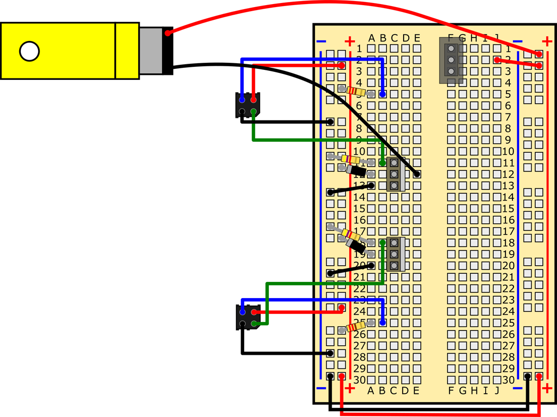
- Replace the 4xAA battery pack with the 3xAA battery pack that is included in your BlueBot kit, as shown in Figure 11. AA batteries provide 1.5 volts (V) each. So, four AA batteries provide 6 V to the motor, while 3 AA batteries only provide 4.5 V. This lower voltage will make the motors slow down.
/-/https/www.sciencebuddies.org/cdn/Files/7227/17/3xAA-breadboard-diagram-11.png)
Figure 11. Replace the 4xAA battery pack with the 3xAA battery pack.
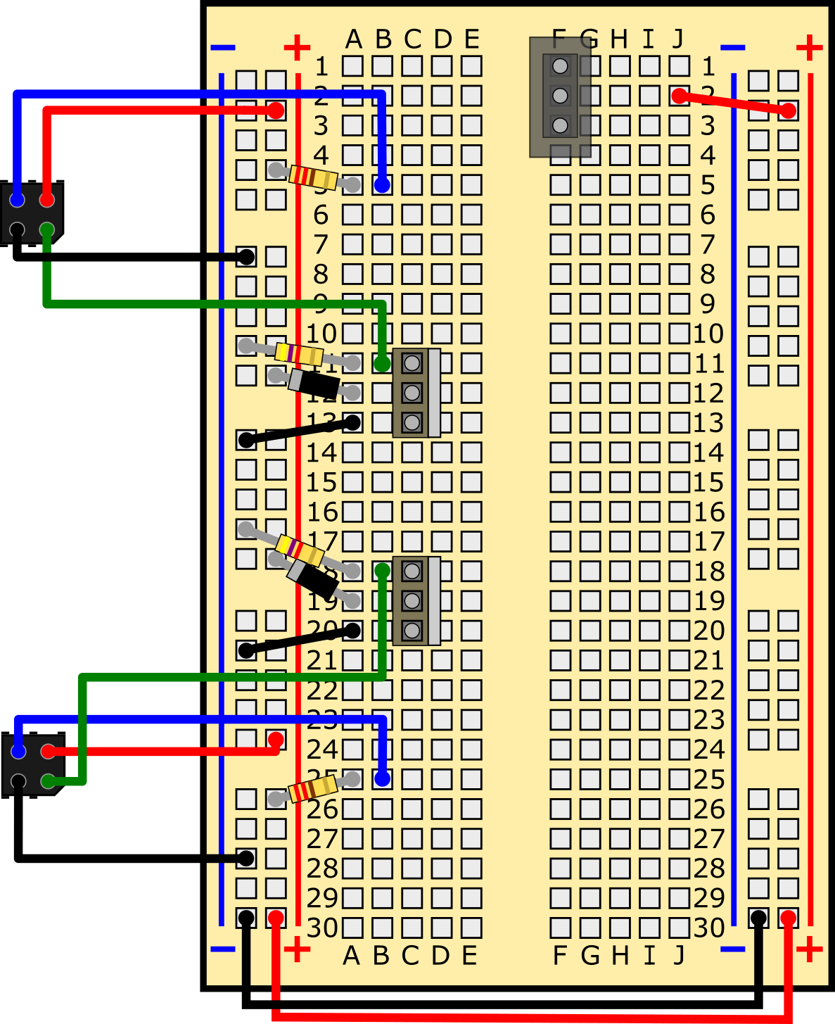
- Replace the 220 Ω resistors (red, red, brown, gold) with 150 Ω resistors (brown, green, brown, gold), as shown in Figure 12.
- These are the "current limiting resistors" for the IR LED in the IR sensor. Since you are decreasing the supply voltage to the LED, you also need to decrease the value of the current limiting resistor. Do an internet search for "LED resistor" if you want to learn more about this topic.
/-/https/www.sciencebuddies.org/cdn/Files/7228/18/150-resistor-diagram-12.png)
Figure 12. Swap out the 220 Ω resistors for 150 Ω resistors (circled in green).
- Test your robot again. It should move slower and have an easier time making turns. If it still overshoots turns, remember that you should also try making the line thicker.
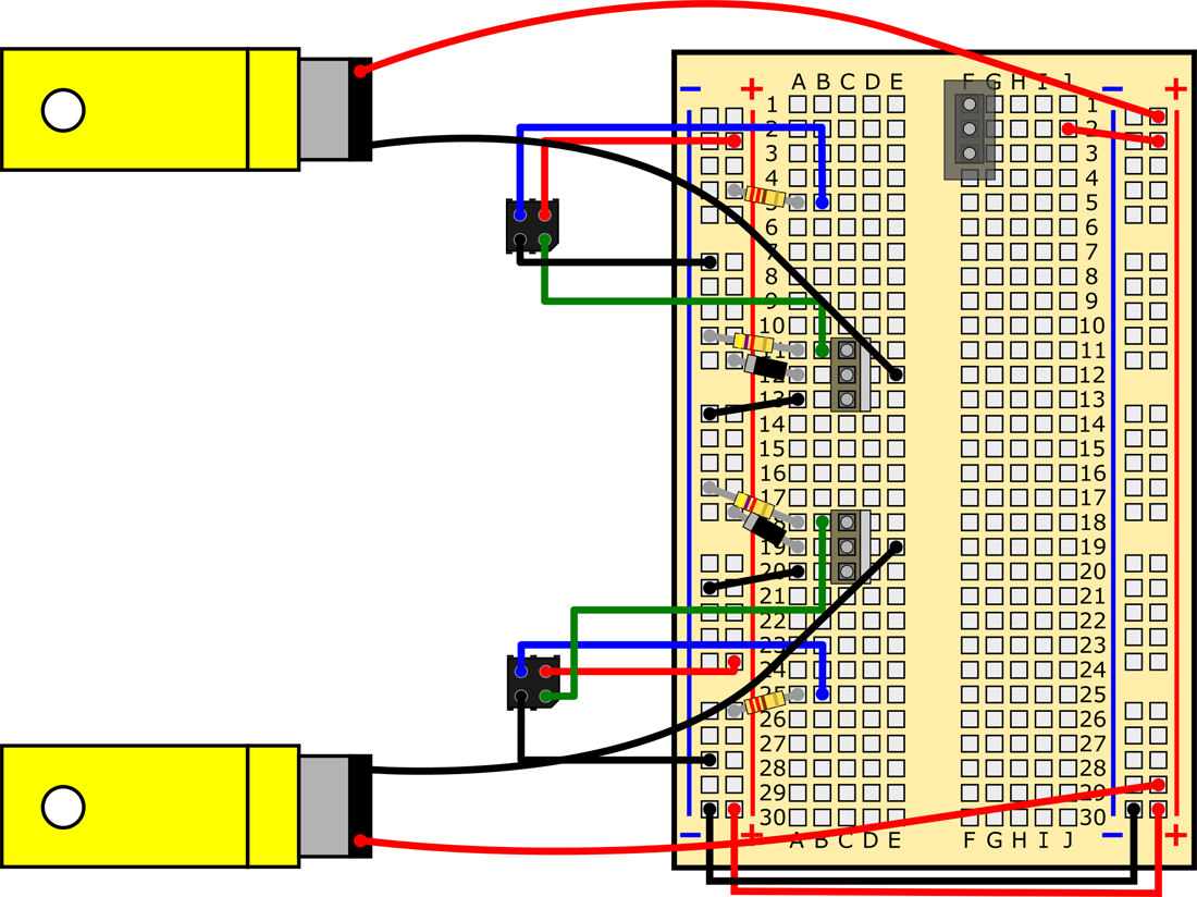
- Advanced: If your robot is still going too fast, you can try slowing it down even more by decreasing the voltage to 3 V. Your BlueBot kit does not include a 2xAA battery pack, so to do this, you will have to remove a battery from the 3xAA pack, and then "short out" one of the connections using a jumper wire, as shown in Figure 13.
/-/https/www.sciencebuddies.org/cdn/Files/7309/10/3xAA-to-2xAA-battery.jpg)
Figure 13. To reduce the battery voltage to 3 V, you need to remove one battery from the 3xAA battery holder and insert a jumper wire in its place.
- Your kit does not include any resistors smaller than 150 Ω. To decrease the current-limiting resistance, you will need to add two more 150 Ω resistors next to the two that are already in your circuit, as shown in Figure 14.
- This is called putting resistors "in parallel," and it actually decreases the total resistance. To learn more about this topic, do an internet search for "resistors in series and parallel."
/-/https/www.sciencebuddies.org/cdn/Files/7229/17/2x150-resistor-14.png)
Figure 14. Add two more 150 Ω resistors in parallel to the first two in order to decrease the current-limiting resistance for each LED when the batteries are only supplying 3 V.
- Test your robot again. It should move much more slowly.
Explore More!
Looking for more robot fun? Explore the World of Robotics with This Suite of Projects!
Troubleshooting
For troubleshooting tips, please read our FAQ: Build a Zippy Line-following Robot (BlueBot Project #3).
Ask an Expert
Global Goals
The United Nations Sustainable Development Goals (UNSDGs) are a blueprint to achieve a better and more sustainable future for all.
/-/https/www.sciencebuddies.org/cdn/Files/19752/5/E-WEB-Goal-09.png)
Variations
- There are three other projects you can do with your BlueBot kit. Since you have already assembled your chassis, all you need to do is build a new circuit.
- A "bristlebot" is a small robot that uses vibration motors instead of geared DC motors, and toothbrush heads instead of wheels. You can put the same circuit you used in this project on a bristlebot to build a miniature version of the robot. Science Buddies has directions for building a light-tracking bristlebot in the Build a Light-Tracking Bristlebot project (the circuit is identical to the one used in the Light-Tracking Bluebot project). Can you adapt the bristlebot to have a line-following circuit instead?
- The Arduino is a very popular type of microcontroller used in robotics. It lets you write a computer program that can read inputs from sensors and use them to control motors. This gives you more precise "control" over your robot's behavior. Can you build a programmable line-tracking robot by adding an Arduino to your chassis? See our page to learn more.
- Instead of using the plastic chassis that came with your BlueBot kit, you can build your own chassis using materials like foam and cardboard, like the one shown in Figure 15. The circuit for the robot remains the same—only the chassis is changed. Can you design and build an improved chassis?
/-/https/www.sciencebuddies.org/cdn/Files/5715/10/Line-following-robot.jpg)
Figure 15. An example of a homemade chassis.
Explore More!
Looking for more robot fun? Explore the World of Robotics with This Suite of Projects!
Frequently Asked Questions (FAQ)
- My robot does not move at all when I put it down on the track and turn it on. What should I do?
- Only one of my robot's wheels is spinning. What is wrong?
- My robot is going backwards! What should I do?
- I have double-checked everything and my robot still does not work. How can I check if something is broken?
- How can I get my robot to slow down so it can follow lines more easily?
- How does the IR sensor work?
- How does a MOSFET work?
- How does the circuit work? What is the circuit diagram?
- What are the circuit diagram symbols for the components in this project?
- How did you make the breadboard diagrams for this project?
-
Try holding the robot chassis in your hands so the wheels are free to spin. Hold a small piece of white paper in front of one of the IR sensors, and slowly move it back and forth. Then try this for the other sensor.
- If the wheels start spinning, you know your circuit is working.
- If the circuit is working properly, but the robot does not move at all when you put it on the floor, the problem is probably the distance of your IR sensors from the floor. They might be too far away or too close. Adjust this distance and then try again.
- If the wheels do not spin, even when you are holding the robot, there may be a problem with your circuit. Go to the next bullet point.
- Double-check all of your breadboard connections. Make sure every lead and jumper wire is firmly pressed into the breadboard. Make sure all of your connections match the breadboard diagrams from the Procedure. You can read about other common breadboard mistakes in the the Common Mistakes section of our breadboard tutorial.
- Make sure all your batteries are properly inserted into the battery holder, with the "+" symbols on the batteries lined up with the "+" symbols inside the holder.
- If you have been using your robot for a long time, or did some of the other BlueBot projects first, your batteries may be dead. Try putting fresh batteries in your robot if none of the other steps work.
- If your robot still does not turn on, follow these steps to see if the problem is with your power switch:
Figure 15. In the top image, the motors' red leads are connected to the power bus, and the black leads are connected to the MOSFETs' drain pins (holes E12 and E19). If this configuration causes your robot to go backwards, just switch the red and black wires for each motor, as shown in the bottom image. Connect the black wires to the power bus, and the red wires to holes E12 and E19. Do not worry about violating the color-coding convention for positive and negative; all this does is reverse the direction in which the motors spin.
- Try plugging your motor's leads directly into the buses on your breadboard (for each motor, one lead to the power bus, one lead to the ground bus). If the motors turn on, then you know that they are working, and the problem is elsewhere in your circuit. If the motors do not turn on, that does not necessarily mean they are broken. There might be a problem with your power supply (see next point).
- Check your breadboard's power supply.
- Set your multimeter to measure DC volts. Four fresh AA batteries should provide just over 6 V.
- Turn your power switch on and measure the voltage between the breadboard's buses. If you do not read a voltage, there may a problem with your power switch (see the first question in this FAQ), but you should also double check that your power switch and the red jumper wire from hole J2 to the power bus are in the right place.
- Unplug the red and black battery pack leads and measure the voltage of the battery pack directly. If you get a reading, then you know your battery pack is working, and the problem is with your breadboard connections or the power switch. If you do not get a reading, make sure all the batteries are in the correct orientation in your battery pack, and that none of the metal clips and springs that hold the batteries in place are loose.
- Make sure the IR LEDs in the IR sensors are working.
- Connect your multimeter in series with the IR LED (meaning, between pin 4 of the IR sensor and ground, or between the 220 Ω resistor and pin 3 of the sensor), and measure current when the robot is switched on. You should measure about 20 mA. If no current is flowing at all, the LED may be burned out, or it might not be receiving power (see above).
- If your multimeter has a diode test function, you could also use that to test the LEDs.
- Test the output of the phototransistors.
- Measure the voltage between pin 2 of an IR sensor and ground (make sure the robot is turned on). When the sensor is aimed at a dark surface, or is very far away from a light surface, this voltage should be close to zero. When the sensor is held close to a white surface, the voltage should increase (to almost the battery pack voltage, but not quite). If this voltage does not change, the phototransistor may not be properly receiving power.
- If the motors work when you plug their leads directly into the buses, and the output voltage of the IR sensors increases when they are held close to a white surface, then the problem is elsewhere in your circuit. You know the individual components work so nothing is "broken." Double and triple-check your wiring. Remember that just one misplaced wire can prevent the entire circuit from working.
/-/https/www.sciencebuddies.org/cdn/Files/6332/8/transistor.png)
Figure 16. Diagram of a bipolar transistor. It has three pins: the base, collector, and emitter. Normally, a small current applied at the base causes a larger current to flow between the collector and emitter. A phototransistor is activated by light instead of electrical current.
/-/https/www.sciencebuddies.org/cdn/Files/6217/15/MOSFET-operation.png)
Figure 17. Simplified explanation of a MOSFET's operation.
The exact description of how a MOSFET works is more complicated than this. As VGS increases past Vth, the current through the MOSFET will continue to increase. Eventually the MOSFET will reach saturation, where no additional current can flow, even if VGS continues to increase. The MOSFET's behavior will also depend on the type of load to which it is attached. The MOSFET used in this project is an N-channel MOSFET, which requires a positive gate voltage to turn on. A P-channel MOSFET requires a negative gate voltage to turn on. Advanced users can refer to the Bibliography for more information on MOSFETs.
Since the circuit consists of two identical halves—one to control each motor—we can just explain how one half of the circuit works. The same explanation applies to the other side.
- The batteries supply a voltage, Vbatt to the circuit. When the switch is closed, V1 = Vbatt. When the switch is open, V1 is "floating", so the circuit does not receive any power.
- The 220 Ω resistor acts as a current-limiting resistor for the IR LED. It prevents too much current from flowing through the LED and burning it out.
- The IR LED emits infrared light. If enough light is reflected back to the sensor, it triggers the base of the phototransistor, allowing current to flow from the collector to the emitter.
- The 4.7 kΩ resistor acts as a pull-down resistor. When the phototransistor is not conducting, it "pulls down" the MOSFET's gate voltage (labeled V2 in Figure 18) to ground. When the phototransistor conducts, V2 will increase, approaching, but not quite reaching, Vbatt.
- When V2 is below the MOSFET's threshold voltage Vth, no current flows through the motor. When V2 exceeds the threshold voltage, the MOSFET allows current to flow, turning the motor on.
- The end result is that when the IR sensor "sees" white, it triggers the MOSFET and turns the motor on. When it "sees" black, it turns the motor off.
- Finally, each motor has a diode connected across its terminals. Motors can create large voltage spikes when they abruptly come to a stop (this has to do with the relationship between electrical current and magnetic fields, if you want to do more research on the explanation). The diodes help prevent damage to the MOSFET by safely discharging the current generated by the voltage spike.
/-/https/www.sciencebuddies.org/cdn/Files/6333/8/line-follower-circuit-diagram.png)
Figure 18. A complete circuit diagram for the line-following robot.
| Item Name | Picture | Breadboard Diagram Symbol | Circuit Diagram Symbol |
|---|---|---|---|
| Battery pack | |||
| Breadboard |
|
/-/https/www.sciencebuddies.org/cdn/Files/7142/6/breadboard-symbol.png) |
N/A |
| Switch | |||
| Jumper wire |
|
||
| DC Motor | |||
| MOSFET |
|
||
| Diode | |||
| 4.7k Ω resistor | |||
| 220 Ω resistor | |||
| IR Sensor |
/-/https/www.sciencebuddies.org/cdn/Files/6337/8/circuit-symbol-IR-emitter-detector.png) |
/-/https/www.sciencebuddies.org/cdn/Files/6299/9/symbol-battery.jpg)
/-/https/www.sciencebuddies.org/cdn/Files/6300/8/symbol-SPDT-switch.jpg)
/-/https/www.sciencebuddies.org/cdn/Files/6301/8/symbol-jumper-wire.jpg)
/-/https/www.sciencebuddies.org/cdn/Files/6302/8/symbol-motor.jpg)
/-/https/www.sciencebuddies.org/cdn/Files/6304/8/symbol-MOSFET.jpg)
/-/https/www.sciencebuddies.org/cdn/Files/6303/8/symbol-diode.jpg)
/-/https/www.sciencebuddies.org/cdn/Files/6335/7/resistor-circuit-symbol.png)
Careers
If you like this project, you might enjoy exploring these related careers:
/-/https/careerdiscovery.sciencebuddies.org/cdn/Files/1725/18/4161_Michelle_Easter_and_Curiousity_Clone.jpg)
/-/https/careerdiscovery.sciencebuddies.org/cdn/Files/1731/17/iStock-1187291213.jpg)
/-/https/careerdiscovery.sciencebuddies.org/cdn/Files/1450/21/iStock-1227179796.jpg)
/-/https/careerdiscovery.sciencebuddies.org/cdn/Files/1223/17/iStock-971549326.jpg)
Contact Us
Our kits are developed in partnership with Home Science Tools®. If you have purchased a kit for this project, Home Science Tools® is pleased to answer any questions not addressed by the FAQ above.In your email, please follow these instructions:
- Include your Home Science Tools® order number.
- Please describe how you need help as thoroughly as possible:
Examples
Good Question I'm trying to do Experimental Procedure step #5, "Scrape the insulation from the wire. . ." How do I know when I've scraped enough?
Good Question I'm at Experimental Procedure step #7, "Move the magnet back and forth . . ." and the LED is not lighting up.
Bad Question I don't understand the instructions. Help!
Good Question I am purchasing my materials. Can I substitute a 1N34 diode for the 1N25 diode called for in the material list?
Bad Question Can I use a different part?
Contact Support

/-/https/img.youtube.com/vi/kvTjzGID3oM/0.jpg)
/-/https/img.youtube.com/vi/clkwb57rEfg/0.jpg)
/-/https/img.youtube.com/vi/subFttvmGng/0.jpg)