Summary
/-/https/www.sciencebuddies.org/cdn/Files/17150/8/drone-steering-thumbnail.png)
/-/https/i.ytimg.com/vi/Rimc2yc6oT0/maxresdefault.jpg)
Introduction
How do quadcopters (drones with four propellers) steer? Find out in this fun project as you program an Arduino to steer a mini popsicle stick drone!
See this page for a complete list of our mini drone projects. You may wish to do the projects in order.
Materials
- DIY Mini Drone Kit
- Electronics Kit for Arduino
- You will also need to gather these items, not included in the kits:
- N-channel MOSFET (4)
- Push button (4 total, 2 included in Arduino kit)
- Identical retractable pens (4)
- Piece of corrugated cardboard
- Scissors
-
Windows or Mac computer. See this page if you have a Chromebook. Your computer will need:
- Access to the Arduino IDE, either installed local version or web-based editor (note that Chromebooks can only use the web version). Watch this video for a comparison of the two options.
- USB port. The Science Buddies kit comes with a USB-A to B cable. The "B" end plugs into the Arduino and the "A" end plugs into your computer. You will need an adapter or different cable if your computer only has USB-C ports. Watch this video to learn about the different types of cables and adapters.
Disclaimer: Science Buddies participates in affiliate programs with Home Science Tools®, Amazon.com, Carolina Biological, and Jameco Electronics. Proceeds from the affiliate programs help support Science Buddies, a 501(c)(3) public charity, and keep our resources free for everyone. Our top priority is student learning. If you have any comments (positive or negative) related to purchases you've made for science projects from recommendations on our site, please let us know. Write to us at [email protected].
Prep Work
- If you do not know how to use a breadboard, refer to our Breadboard Tutorial before you continue.
- If you have never used an Arduino before, refer to our How to Use an Arduino guide.
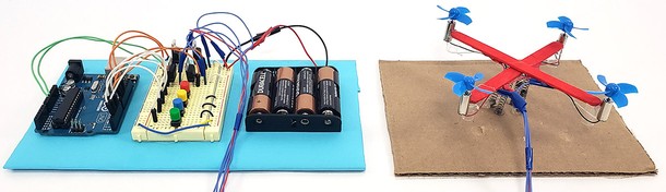
- Follow the instructions in the DIY Mini Drone activity to build your drone, with the following important changes:
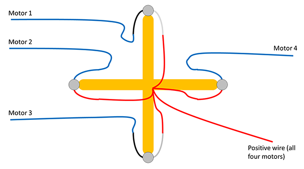
- Do not connect all four motors' negative wires (the black and blue wires) to each other. Each of these wires should have its own longer wire connected to it. This gives your drone a total of five external wires: four individual negative wires, and one positive wire, which is connected to all the motors' positive wires (the red and white wires). See the diagram. The motors are numbered 1–4, going counterclockwise from the top.
- You do not need to build a vertical guide pole for your drone for this project. See the next section.
/-/https/www.sciencebuddies.org/cdn/Files/17156/8/motor-wiring.png)
Instructions
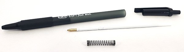
- Disassemble four identical retractable pens and remove the springs. You can usually do this by unscrewing part of one end of the pen, and removing the inner parts.
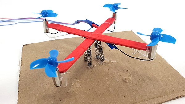
- Hot-glue the springs to the bottom of your drone. The springs should be equally spaced around the center of the drone, where the popsicle sticks intersect.
- Glue the springs to the center of a piece of cardboard, such that the drone rests on the springs. If needed, shorten the straws on the drone so there is at least 1 cm of space between the straws and the ground.
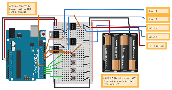
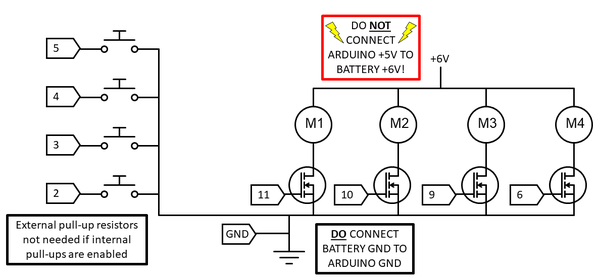
- Orient the breadboard so it is facing you with the writing upright. Then connect all of the following, as shown in the breadboard diagram (click for a bigger version of the diagram). If you know how to read a circuit schematic, you can use that instead. This circuit has a lot of parts! Work slowly and carefully check your wiring.
- Arduino 5V pin to left-side breadboard positive bus.
- Arduino GND pin to breadboard ground bus.
- Breadboard left ground bus to breadboard right ground bus.
- Do not connect the breadboard's left positive bus to the right positive bus. You will use these buses for two different voltage levels (5 V from the Arduino and 6 V from the battery pack). Connecting them will cause a short circuit.
- Put four MOSFETs in the breadboard at the following locations, with the writing on their fronts facing to your right:
- H1, H2, H3
- A5, A6, A7
- H9, H10, H11
- A13, A14, A15
- Put four push buttons in the breadboard, with their pins straddling the middle gap, in the following rows:
- 16 and 18
- 20 and 22
- 24 and 26
- 28 and 30
- Use jumper wires to make the following connections to the Arduino:
- Arduino pin 2 to hole A28
- Arduino pin 3 to hole A24
- Arduino pin 4 to hole A20
- Arduino pin 5 to hole A16
- Arduino pin 6 to hole I3
- Arduino pin 9 to hole I11
- Arduino pin 10 to hole B15
- Arduino pin 11 to hole B7
- Use jumper wires to connect all of the following breadboard holes to the ground bus:
- C5
- B13
- J1
- J9
- J18
- J22
- J26
- J30
- Connect the motors' negative wires to the following holes:
- Motor 1 to B6
- Motor 2 to D14
- Motor 3 to J10
- Motor 4 to J2
- Connect the shared motor positive wire to the right-side positive bus.
- Finally, connect the battery pack:
- Black lead to the ground bus
- Red lead to the right-side positive bus
- Upload the code to your Arduino.
- Download drone-steering-4-buttons.ino to your computer. If you have some computer programming experience, you can look through the code and read the comments to understand how it works.
- Connect the Arduino to your computer with the USB cable.
- Open drone-steering-4-buttons.ino in the Arduino IDE.
- Press the "Upload" button to send the code to your Arduino.
- Test your drone. One at a time, press and hold down each one of the buttons.
 What does the drone do when you hold each button down?What happens if you change the values of the defaultSpeed or speedChange variables in the code? Note: Make sure that the sum of these two values added together does not exceed 255, or the value will "overflow" (wrap back around to zero).
 - Troubleshooting:
- If your drone's motors do not spin at all, double-check all of your breadboard wiring. A single misplaced wire can prevent the entire circuit from working.
- To confirm that your drone is working, temporarily connect the positive wire to the breadboard's positive bus, and all four negative wires to the breadboard's ground bus. This should make all four motors spin.
- Make sure all your wires are connected to the correct Arduino pins. The code does not "know" which pins you have plugged the wires into. You need to plug wires into the pins that are used in the code. If some of your buttons work but others do not, you might have connected wires to the wrong pins.
/-/https/www.sciencebuddies.org/cdn/Files/17157/9/retractable-pen-spring.jpg)
/-/https/www.sciencebuddies.org/cdn/Files/17158/8/drone-mounted-on-springs.jpg)
/-/https/www.sciencebuddies.org/cdn/Files/17153/11/drone-arduino-steering-breadboard-diagram.png)
/-/https/www.sciencebuddies.org/cdn/Files/17154/8/drone-arduino-steering-circuit-diagram.png)
/-/https/www.sciencebuddies.org/cdn/Files/17159/8/drone-arduino-steering.jpg)
Cleanup
What Happened?
When you run the code, at first the Arduino makes all four motors spin at the same speed. When you push one of the buttons, the program makes two adjacent motors speed up, and the two opposite motors slow down. The motors that spin faster generate more lift (the force that pushes the drone up). The motors that spin slower generate less lift. This creates uneven forces on opposite sides of the drone (also called a torque), making it tilt in one direction. Each button is programmed to make the drone tilt in a different direction.
Digging Deeper
In this project, you programmed your drone's steering behavior to respond to four buttons. You could make the drone tilt forward, backward, left, or right. However, you could not control the amount of tilt or the direction of tilt with much precision. Real drone controllers use analog joysticks that allow more continuous variation in the controls, allowing you to steer the drone in any direction and control how fast it moves.
Real drones also contain an on-board electronic sensor called an accelerometer. The accelerometer measures the drone's angle of tilt. An on-board computer automatically makes small adjustments to the motors' speed to keep the drone level. This way, the human operator can concentrate on higher-level tasks, like using the drone for aerial photography, without constantly having to worry about keeping the drone balanced.
You can learn how the example code for this project works by reading the detailed comments in the code.
Ask an Expert
For Further Exploration
- Can you modify your program to make the drone steer in the yaw direction (rotate about a vertical axis through the center of the drone)?
- Can you modify your code so you can push four buttons at once, allowing you to tilt the drone in more directions?
- Can you replace the button controls in your circuit with an analog joystick?
/-/https/www.sciencebuddies.org/cdn/Files/16847/5/DIY-mini-drones-thumbnail.jpg)
/-/https/www.sciencebuddies.org/cdn/Files/17038/5/DIY-mini-drone-altitude-control-circuit.jpg)
/-/https/www.sciencebuddies.org/cdn/Files/17047/6/diy-mini-drone-arduino.jpg)
/-/https/www.sciencebuddies.org/cdn/Files/17160/5/drone-joystick-thumbnail.jpg)
/-/https/www.sciencebuddies.org/cdn/Files/17460/5/drone-automatic-balancing-thumbnail.jpg)
/-/https/www.sciencebuddies.org/cdn/Files/17334/5/drone-motion-control-thumbnail.jpg)
/-/https/www.sciencebuddies.org/cdn/Files/17476/5/popsicle-stick-drone-free-flight-thumbnail.jpg)
/-/https/careerdiscovery.sciencebuddies.org/cdn/Files/1163/18/pexels-photo-1181472.jpg)
/-/https/careerdiscovery.sciencebuddies.org/cdn/Files/1655/17/pexels-photo-2898316.jpg)
/-/https/careerdiscovery.sciencebuddies.org/cdn/Files/835/18/msfc-202000343.jpg)
/-/https/careerdiscovery.sciencebuddies.org/cdn/Files/1223/17/iStock-971549326.jpg)
/-/https/img.youtube.com/vi/tz_9OInLRIU/0.jpg)
/-/https/img.youtube.com/vi/KuA_tjYqODc/0.jpg)
/-/https/img.youtube.com/vi/uIV031bnmFA/0.jpg)