Summary
/-/https/www.sciencebuddies.org/cdn/Files/17460/5/drone-automatic-balancing-thumbnail.jpg)
/-/https/i.ytimg.com/vi/WGlJMt5etr8/maxresdefault.jpg)
Introduction
How do drones automatically balance themselves when you let go of the controls? Find out in this project as you build and program an experimental setup to make a drone automatically control its tilt angle about a single axis.
See this page for a complete list of our mini drone projects. You may wish to do the projects in order.
Materials
- DIY Mini Drone Kit
- Electronics Kit for Arduino
- You will also need to gather these items, not included in the kits:
- N-channel MOSFET (4)
- Push button (4 total, 2 included in Arduino kit)
- ADXL355 triple-axis accelerometer breakout board
- Male-female header pins
- 2-axis analog joystick
- 100 kΩ resistors (3). A resistor kit is available from SparkFun (useful if you will be doing other electronics projects). Otherwise you can buy the resistors individually from Jameco.
- 0.1 μF capacitors (3). Available as individual capacitors or as part of a capacitor kit.
- Small cardboard box
- Wooden skewers (2)
- Small binder clips (2)
- Twist ties
- Double-sided foam tape
- Soldering iron
- Lead-free solder
- Optional: Heat shrink tubing and heat gun
- Identical retractable pens (4)
- Piece of corrugated cardboard
- Scissors
-
Windows or Mac computer. See this page if you have a Chromebook. Your computer will need:
- Access to the Arduino IDE, either installed local version or web-based editor (note that Chromebooks can only use the web version). Watch this video for a comparison of the two options.
- USB port. The Science Buddies kit comes with a USB-A to B cable. The "B" end plugs into the Arduino and the "A" end plugs into your computer. You will need an adapter or different cable if your computer only has USB-C ports. Watch this video to learn about the different types of cables and adapters.
Disclaimer: Science Buddies participates in affiliate programs with Home Science Tools®, Amazon.com, Carolina Biological, and Jameco Electronics. Proceeds from the affiliate programs help support Science Buddies, a 501(c)(3) public charity, and keep our resources free for everyone. Our top priority is student learning. If you have any comments (positive or negative) related to purchases you've made for science projects from recommendations on our site, please let us know. Write to us at [email protected].
Prep Work
- Follow the instructions in the DIY Mini Drone activity to build your drone, with the following important changes:
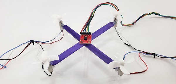
- Do not connect any of the motor wires to each other. Add a separate extension wire (roughly 0.5 m) to each individual motor wire—8 wires total. To make it easier to keep track of the wires, make the extension wire colors match the motor wires.
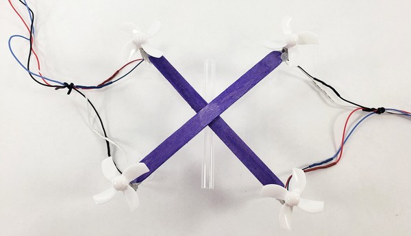
- Glue a single piece of straw (about 5–6 cm long) to the underside of the drone, dividing the drone into two halves.
- Bundle together the motor wires on each side using twist ties (four wires per bundle). This will help prevent the wires from getting tangled.
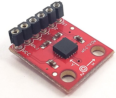
- The accelerometer breakout board does not come with header pins attached, so you will need to solder them on yourself. Refer to the Science Buddies soldering tutorial if you do not know how to solder.
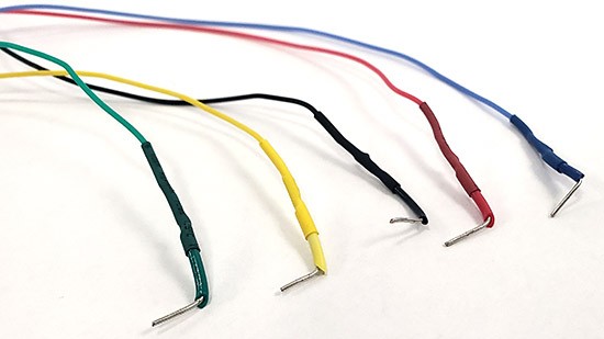
- Solder short pieces of solid-core jumper wire to the ends of five 1 m pieces of stranded wire. Wrap the exposed solder connections in electrical tape or, if available, use heat shrink tubing.
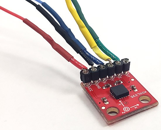
- Plug one end of each wire into the header pins on the accelerometer. You will plug the other ends into your Arduino in the next section.
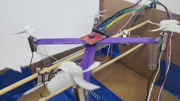
- Use double-sided tape to mount the accelerometer to the center of the drone's frame, as pictured. The wires coming off the accelerometer should be aligned with the horizontal straw. Use twist ties to bundle the accelerometer wires together so they do not get tangled.
- Poke a wooden skewer through one side of a cardboard box, about 2 inches from the top. Then thread the drone onto the skewer through the horizontal straw. Poke the skewer straight across to make a hole in the opposite side of the box so the skewer and drone are suspended. Add a second skewer directly below the first one. This will prevent the drone from rotating more than 180° and the wires from getting twisted. Add binder clips to both ends of the horizontal straw to prevent the drone from sliding back and forth. Depending on the width of the box, you might need to cut down the side walls so the drone can rotate freely without hitting them.
/-/https/www.sciencebuddies.org/cdn/Files/17461/5/drone-wires-bundled.jpg)
/-/https/www.sciencebuddies.org/cdn/Files/17335/8/accelerometer-header-pins.jpg)
/-/https/www.sciencebuddies.org/cdn/Files/17336/5/shrink-wrapped-wires.jpg)
/-/https/www.sciencebuddies.org/cdn/Files/17337/6/accelerometer-wires.jpg)
/-/https/www.sciencebuddies.org/cdn/Files/17462/5/drone-accelerometer.jpg)
/-/https/www.sciencebuddies.org/cdn/Files/17463/5/drone-balancing-experiment-closeup.jpg)
Instructions
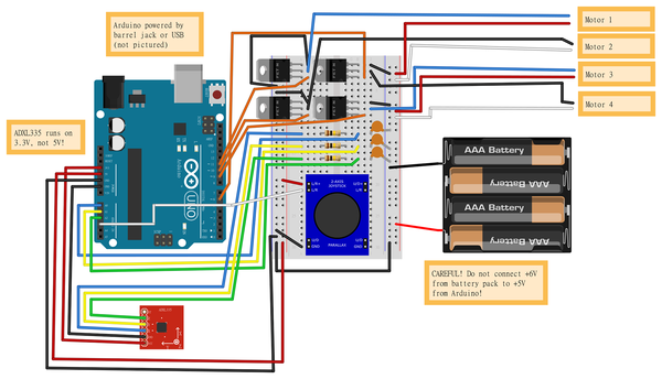
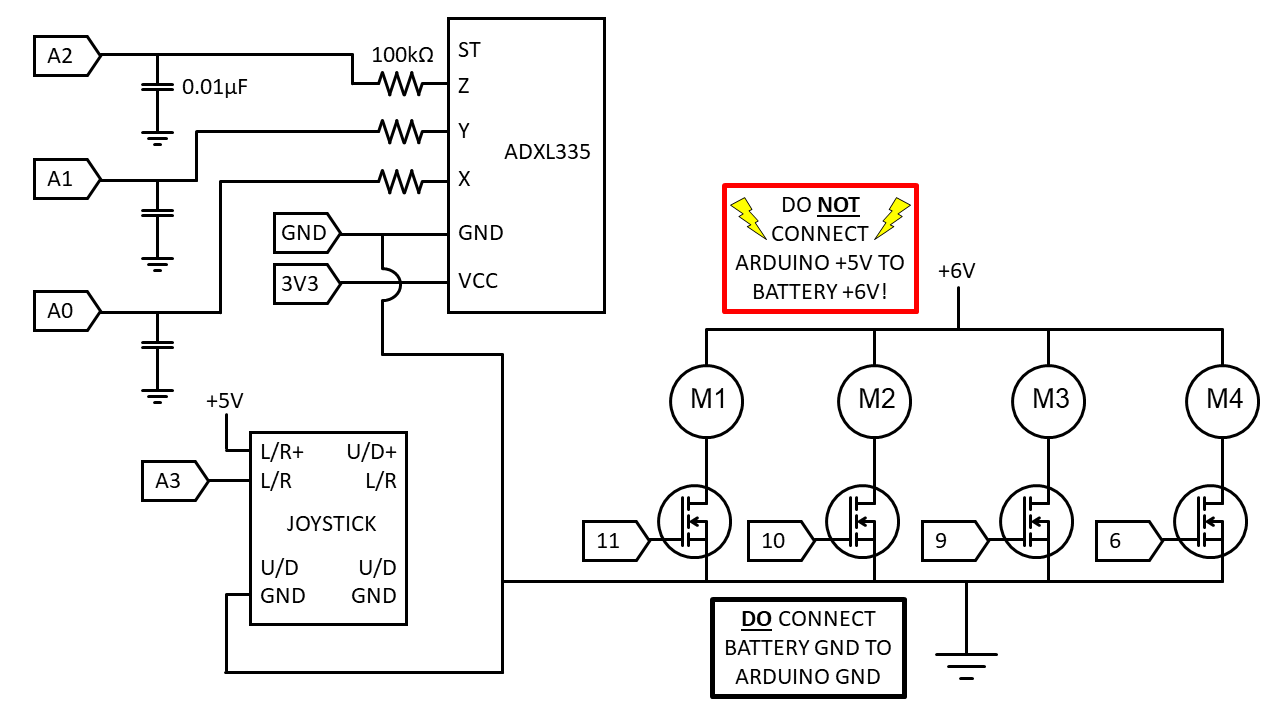
- Build the following circuit. Click for bigger versions of the breadboard diagram and circuit diagram). A few important notes:
- The accelerometer is powered by the Arduino's 3.3 V supply, not 5 V.
- Make sure you do not short-circuit the Arduino's 5 V supply to the 6 V from the 4xAA battery pack.
- This circuit has a lot of wires! Keep your wiring neat. It helps to color-code your wires. You do not need to use the colors shown in the diagram, but use something that makes sense to you. Remember to use twist ties to bundle and organize the long wires to the motor and the accelerometer. Make wires on the breadboard as short as possible so the circuit does not get too messy.
- Some more information about the connections:
- Motors 1, 2, 3, and 4 are controlled by MOSFETs connected to Arduino pins 11, 10, 9, and 6 respectively (these are pins with PWM functionality for controlling motor speed).
- The X, Y, and Z outputs from the accelerometer are each sent through a low-pass filter with a 100 kΩ resistor and a 0.1 μF capacitor. The outputs of the three filters are sent to Arduino analog input pins A0, A1, and A2 for X, Y, and Z, respectively.
- The L/R output from the analog joystick is sent to Arduino analog input A3.

- Download drone_tilt_control.ino. If you have not already done the DIY Mini Drone: Motion Control project, you will need to calibrate your accelerometer by following step 2 in the procedure of that project before you continue. Do this with drone_tilt_control.ino, not motion_control.ino. The procedure is the same, you just need to uncomment the section at the end of the code that prints the accelerometer readings to the serial monitor.
- Read through the commented code to attempt to understand how it works. The program uses the analog input from the joystick to calculate a desired tilt angle, and uses the accelerometer to measure the actual tilt angle. It calculates the error, or the difference between these two angles, and uses a proportional-integral-derivative (PID) controller to try and reduce the error. The PID controller has three gains: KP, KI, and KD. You will need to "tune," or adjust, these parameters in order to get your drone to balance.
- The program starts out with a very small value for KP, while KI and KD are zero. Try running the program and observing your drone's behavior.
 What happens if you tilt the joystick side to side? What happens if you bump the drone to tip it with your finger?
 - Now, increase the value of KP slightly (for example, from 0.01 to 0.02) and re-upload the program.How does your drone's behavior change?
- Keep increasing the value of KP until the drone starts to overshoot its target angle and oscillate back and forth. Reduce KP to about half of that value.
- Next, start slowly increasing KI. Again, observe your drone's behavior as you increase KI.Can you find a value that seems "just right," where the drone does not respond too slowly to joystick input or disturbances, but does not oscillate or behave erratically?
- Optionally, try changing the value of KD.What effect does KD have on your drone's behavior?
/-/https/www.sciencebuddies.org/cdn/Files/17464/5/drone-pitch-control-breadboard-diagram.png)
/-/https/www.sciencebuddies.org/cdn/Files/17465/5/drone-pitch-control-circuit-diagram.png)
Cleanup
What Happened?
Eventually, after adjusting the parameters, you should be able to find settings that allow you to steer the drone with the joystick, and such that the drone will auto-correct itself when you bump it with your finger. Ideally, the drone will respond to inputs quickly, without over-correcting too much and oscillating.
You should have found that initially, the value for KP was too small. The drone might seemingly not have responded to joystick input at all, or failed to right itself when tipped with your finger. Increasing the value of KP will cause the drone to respond to inputs, but it might respond slowly, or have an offset error between the target and actual tilt angles. Increasing KI can also help the drone respond more quickly and eliminate the offset error. However, increasing either parameter too much can cause the drone to oscillate wildly, as it overshoots its target angle and then over-corrects back in the other direction. KD does not have as much of an effect on the drone's behavior unless you make the value very large.
Digging Deeper
PID controllers are a very common type of controller, used when you need something more complex than simple on-off control, like that used by many thermostats. When the temperature dips below a certain point, they turn on the heat. When the temperature gets above a certain point, they turn off the heat. However, you can imagine how this would not be a very good approach for something like cruise control in a car. You would not want to alternate between slamming on the gas and slamming on the brakes in order to maintain a constant speed. The same applies to a drone—imagine trying to fly a drone if the propellers could only go full speed or turn off completely, with nothing in between!
A PID controller combines three terms to calculate the control input to a system (in the case of your drone, that control input is the speed change of the motors, but this concept applies generally to any system). Each term has a gain associated with it (KP, KI, and KD). The proportional term is simply proportional to the error, or the difference between the desired and actual measurements. The integral term is proportional to the integral, or accumulated error. The derivative term is proportional to the derivative, or rate of change, of the error. Changing each gain has a different effect on the system. The video series in the Additional Resources section explains this in more detail with several examples.
There are many different ways to "tune" a controller, or choose the gain values so the system has the response that you want. You used a simple manual tuning method in this project, but many more-advanced methods exist. The Wikipedia link in the description lists some of the methods.
Ask an Expert
For Further Exploration
- Try some of the other controller tuning methods listed in the Additional Resources section. Do any of them work better than the basic manual tuning method you used in this activity?
- There are many things you could change about the example code other than the gain values. For example, what happens if you change the defaultSpeed variable?
- The outputs from the accelerometer go through a low-pass RC filter before going to the Arduino's analog inputs. This helps filter out some high-frequency noise resulting from motor vibrations. How effective are these filters? How noisy is the accelerometer data, and how does this affect the use of a derivative term in the PID controller? Could you implement a software filter instead of (or in addition to) a hardware filter, for example, by averaging several successive accelerometer readings, or removing outlier measurements? Note that filtering the data is very important when using derivative control. If the accelerometer data is noisy or "spiky," then the derivative term of the controller will bounce between positive and negative very rapidly.
Related Resources
Activities
/-/https/www.sciencebuddies.org/cdn/Files/16847/5/DIY-mini-drones-thumbnail.jpg)
/-/https/www.sciencebuddies.org/cdn/Files/17038/5/DIY-mini-drone-altitude-control-circuit.jpg)
/-/https/www.sciencebuddies.org/cdn/Files/17047/6/diy-mini-drone-arduino.jpg)
/-/https/www.sciencebuddies.org/cdn/Files/17160/5/drone-joystick-thumbnail.jpg)
/-/https/www.sciencebuddies.org/cdn/Files/17334/5/drone-motion-control-thumbnail.jpg)
/-/https/www.sciencebuddies.org/cdn/Files/17150/8/drone-steering-thumbnail.png)
/-/https/www.sciencebuddies.org/cdn/Files/17476/5/popsicle-stick-drone-free-flight-thumbnail.jpg)
Links
- Understanding PID Control, Part 1: What is PID Control?, MATLAB YouTube
- PID controller: overview of tuning methods, Wikipedia
/-/https/careerdiscovery.sciencebuddies.org/cdn/Files/1163/18/pexels-photo-1181472.jpg)
/-/https/careerdiscovery.sciencebuddies.org/cdn/Files/1655/17/pexels-photo-2898316.jpg)
/-/https/careerdiscovery.sciencebuddies.org/cdn/Files/835/18/msfc-202000343.jpg)
/-/https/careerdiscovery.sciencebuddies.org/cdn/Files/1223/17/iStock-971549326.jpg)
/-/https/img.youtube.com/vi/l-VWX6ndGpA/0.jpg)
/-/https/img.youtube.com/vi/jTE2IV8vJ48/0.jpg)
/-/https/img.youtube.com/vi/tSsKYdh9_7w/0.jpg)