Abstract
Beginner robotics projects like the Art Bot and Bristlebots are fun, but the robots wobble around randomly and cannot steer. If you are ready for a robotics project that is a little more advanced (that does not require any programming), try this one out! You will build your own steerable robot with a wired remote control.Summary
/-/https/i.ytimg.com/vi/r0UDLuV6058/maxresdefault.jpg)
Objective
Design and build a steerable robot.
Introduction
/-/https/www.sciencebuddies.org/cdn/Files/18491/5/steerable-robot-thumbnail.jpg)
In this project you will build a simple steerable robot that uses two motors to spin the robot's wheels. You will also build a controller that lets you turn each motor on and off independently. That means that when both motors spin, both wheels spin, causing the robot to drive straight. When only one motor spins, only one wheel spins, causing the robot to turn (Figure 1). Note: the robot only has two wheels, and balances on a third point that slides around on the floor.
/-/https/www.sciencebuddies.org/cdn/Files/18496/5/robot-steering-diagram.png)
Figure 1. Top view of the robot. When both wheels spin, the robot drives straight. When only the left wheel spins, the robot turns right. When only the right wheel spins, the robot turns left.
Your robot's motors are controlled by an electrical circuit. An electrical circuit is a path that allows electrical current to flow. The motor spins when both of its wires are connected to a battery, which provides electrical power. The connections between the battery and motor create a closed circuit, which lets current flow, making the motor spin. When one wire is disconnected, this creates an open circuit, and current cannot flow, so the motor stops spinning (Figure 2).
/-/https/www.sciencebuddies.org/cdn/Files/18497/5/open-closed-circuits.png)
Figure 2. Left: a closed circuit, where current flows through the motor and it spins. Right: an open circuit, where no current flows through the motor and it does not spin.
Buttons on the wired remote allow you to easily control the robot. There are many different types of buttons and switches. In this project, you will use a type of button that creates a closed circuit only when you press it. When you release the button, it creates an open circuit. You will place a button in series with a motor. This means that the button and motor are connected end-to-end, so any electrical current that flows through the button will then flow through the motor. That means that current can only flow through the motor when you press the button and make a closed circuit (Figure 3).
/-/https/www.sciencebuddies.org/cdn/Files/18498/5/open-closed-circuits-button.png)
Figure 3. A series circuit with a battery, button, and motor. The button must be pressed to create a closed circuit and make the motor spin.
However, your robot needs two motors to steer. You will connect a second button and motor in parallel to the first button and motor. With this configuration, electrical current can split and flow through each button-motor pair separately. This means you can control the two motors independently (Figure 4).
/-/https/www.sciencebuddies.org/cdn/Files/18499/5/parallel-circuit-buttons.png)
Figure 4. The complete circuit for your robot. Each button is in series with a motor. The button/motor pairs are in parallel with each other. Top left: neither button is pressed, neither motor spins. Top right: both buttons are pressed, both motors spin. Bottom left: only the left button is pressed, only the left motor spins. Bottom right: only the right button is pressed, only the right motor spins.
The instructions for this project show how to build the circuit for your robot as shown in Figure 4. You will use a breadboard to build your circuit. If you do not know how to use a breadboard, see the reference in the Bibliography.
Design and construction of the physical robot, such as what you use to build the body, and where and how you attach the circuit parts, are up to you. You can use the engineering design process to design, build, and test your robot. See the reference in the Bibliography to learn more about the engineering design process.
Circuit Diagrams
Engineers use circuit diagrams to represent electrical circuits. Instead of pictures or graphics that look like the real parts, these diagrams use symbols to represent the parts. You do not need to understand circuit diagrams yet, but they are easier to draw and you might see them in a science or engineering class. Figure 5 shows a circuit diagram that is equivalent to the "picture" of the circuit in Figure 4.
/-/https/www.sciencebuddies.org/cdn/Files/18500/5/steerable-robot-circuit-diagram-text.png)
Figure 5. Circuit diagram for the robot. The symbols in this Figure match the pictures of the parts in Figure 4.
Terms and Concepts
- Robot
- Motor
- Circuit
- Current
- Battery
- Closed circuit
- Open circuit
- Series
- Parallel
- Breadboard
- Engineering design process
- Circuit diagram
Questions
- What is the difference between open and closed circuits? Which one do you need for current to flow through a motor?
- What is the difference between series and parallel circuits?
- What is the engineering design process and how is it different from the scientific method?
Bibliography
- Science Buddies Staff (n.d.). Engineering Design Process. Science Buddies. Retrieved April 18 2022.
- Science Buddies Staff (n.d.). How to Use a Breadboard for Electronics and Circuits. Science Buddies. Retrieved April 19, 2022.
- Science Buddies Staff (n.d.). Wire Stripping Tutorial. Science Buddies. Retrieved April 19, 2022.
- Dokter, P. (n.d.). Series and Parallel Circuits. SparkFun Electronics. Retrieved April 18, 2022.
Materials and Equipment
You will need the following supplies to build your robot. Availability of electronic components may vary, so we have listed several different vendors as options in Table 1. If a part is not available at one vendor, you may need to search for an equivalent replacement part or check another vendor. If you have trouble finding a part, you can ask for help in our Ask an Expert forums.
Quantities listed are the amounts needed to build one robot. Some vendors (usually Amazon) may sell certain parts in bulk, but many of these parts will be useful if you plan on doing more electronics projects in the future. Note that while you can build the robot using just one color of wire, having at least two different colors (usually red and black) will make it easier to color-code your circuit.
| Part | Qty | SparkFun | Jameco | Amazon | Note |
|---|---|---|---|---|---|
| Motors | 2 | SparkFun motors | Jameco motors | Amazon motors (wheels included) | Wheels and motors also included in the Bluebot kit |
| Wheels | 2 | SparkFun wheels | Not available | Included with motors | |
| Mini breadboard | 2 | SparkFun breadboard | Jameco breadboard | Amazon breadboard | Different colors available |
| 2xAA battery holder | 1 | SparkFun battery holder | Jameco battery holder | Amazon battery holder | Available with or without cover and switch |
| AA batteries | 2 | SparkFun batteries | Jameco batteries | Amazon batteries | |
| Momentary pushbuttons | 2 | SparkFun buttons | Jameco buttons | Amazon buttons | |
| 22 AWG stranded wire | 12 feet | SparkFun stranded wire | Jameco stranded wire | Amazon stranded wire | Also called "hook up wire." Available in different colors. |
| 22 AWG solid wire | 1 foot | SparkFun solid wire | Jameco solid wire | Amazon solid wire | You can also purchase a "jumper wire kit" with pre-cut short wires. |
| Wire strippers | 1 | SparkFun wire strippers | Jameco wire strippers | Amazon wire strippers | Wire strippers have different size ranges. Make sure the range includes 22 AWG. |
| Electrical tape | 1 roll | Not available | Jameco electrical tape | Amazon electrical tape |
You will also need craft supplies and tools to build the body of your robot. This list includes materials used to build the robot shown in the project video. However, this is just a suggestion. You can choose different materials to build your robot.
- Corrugated cardboard
- Paper towel or toilet paper tube
- Scissors
- Glue
- Decorations (googly eyes, pipe cleaners, etc.)
Disclaimer: Science Buddies participates in affiliate programs with Home Science Tools®, Amazon.com, Carolina Biological, and Jameco Electronics. Proceeds from the affiliate programs help support Science Buddies, a 501(c)(3) public charity, and keep our resources free for everyone. Our top priority is student learning. If you have any comments (positive or negative) related to purchases you've made for science projects from recommendations on our site, please let us know. Write to us at [email protected].
Experimental Procedure
- Make drawings of what you want your robot to look like. Think about these questions before you start drawing. Note that in order for the robot to drive properly, the motors should be parallel to each other, on opposite sides of the robot.
- What materials will you use to make the body of your robot?
- Where will you attach the motors, breadboard, and batteries to your robot?
- Will you decorate your robot?
- Start building your robot's circuit as shown in Figure 6. If you do not know how to use a breadboard or strip wire, see the references in the bibliography. If you prefer to work with a circuit diagram, see Figure 5 in the introduction.
- Connect the battery pack's red and black wires to two different rows on the breadboard.
- Connect both motors' black wires to the same row as the battery pack's black wire.
- Connect both motors' red wires to two separate rows on the breadboard.
- Put the two pushbuttons in the other breadboard such that they straddle the gap in the middle of the breadboard.
- Do not connect the two breadboards to each other yet. You will prepare the wires to do this in the next step.
- Note that the arrangement of parts in a breadboard diagram does not need to match the physical layout of the parts when you build the circuit, as long as the wires remain connected in the same way. For example, in Figure 6 you could put the battery pack in between the two breadboards, or you could rotate the motors 90 degrees so they point outward (which you will need to do when building your robot). The physical location of the parts does not affect the circuit, only how the wires are connected.
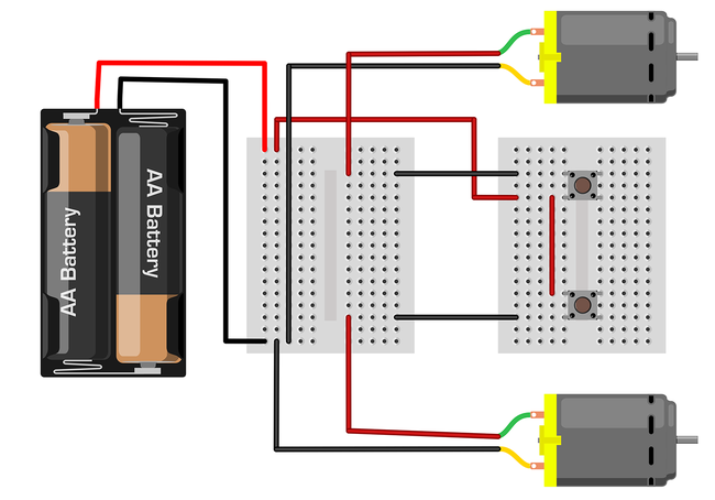
Figure 6. Breadboard diagram of the robot's circuit. Note: the motors in this diagram do not look like the motors you will use to build your robot. That is OK. The purpose of this diagram is to show the electrical connections. - Cut three long pieces of stranded wire, about 4 feet each. The stranded wire is too flexible to push into the breadboard holes, so you need to attach short pieces of solid wire to the ends, as shown in Figure 7. Note: if you have access to a soldering iron, you can ask an adult for help and use it for this step.
- Strip about 1 cm of insulation off each end of each wire.
- Cut six short pieces of solid wire, about 3–4 cm each.
- Strip about 1 cm of insulation off each end of the short pieces of solid wire (Figure 7.1).
- Use your fingers or the tips of your wire strippers to bend the ends of each wire into a hook shape (Figure 7.2).
- Hook a piece of solid wire onto the end of a piece of stranded wire. Twist the ends together, then use the tip of your wire strippers to crimp them together (Figure 7.3).
- Wrap the connection in electrical tape so there is no exposed metal (Figure 7.4).
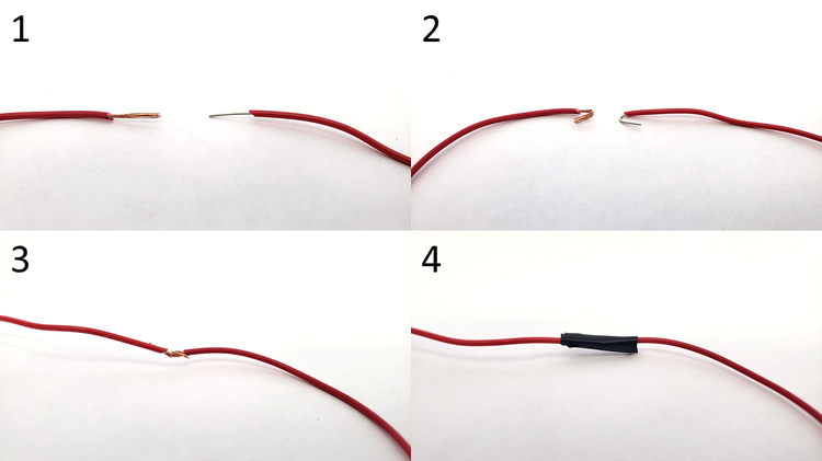
Figure 7. The process to attach a piece of solid wire to the end of a piece of stranded wire. - Use the three wires you prepared in step 3 to connect the two breadboards to each other as shown in Figure 6.
- Use one long wire to connect one pin of one of the buttons to the red wire of one of the motors.
- Use another long wire to connect one pin of the other button to the red wire of the other motor.
- Use your remaining long wire to connect one unconnected pin on one button to the battery pack's red wire.
- Cut a short piece of solid wire and strip the ends. Use it to connect the wire from step c to the remaining unconnected pin on the other button.
- Put the batteries in the battery holder. Make sure the "+" symbols on the batteries line up with the "+" symbols in the battery holder.
- Press one of the buttons and hold it down. One of the motors should spin, and stop when you release the button. Try the other button, then try holding both buttons down at once. If one or both of your motors do not spin, you will need to troubleshoot:
- Make sure the batteries are in the battery holder correctly.
- Make sure none of the breadboard wires came out while you were handling the circuit. Remember that you need a closed circuit for electrical current to flow. If a wire comes loose, you will have an open circuit.
- Make sure your twisted connections between solid and stranded wire have not come loose. If needed, remove the electrical tape and re-crimp the wires together.
- Make sure wires are connected by putting them in the same row of the breadboard. Breadboard holes are connected internally in sets of five (in each half row). The holes are not connected to holes in the adjacent rows directly above or below them. In other words, if you try to connect wires by putting them in the same column instead of the same row, your circuit will not work. See the circled area in Figure 8.
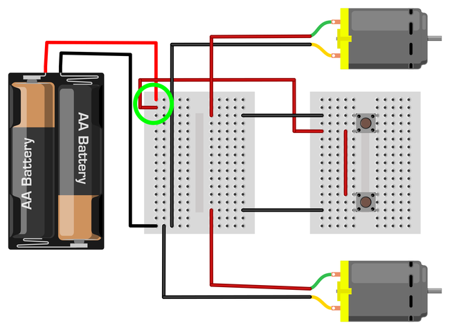
Figure 8. Example of an incorrect circuit. The red wire in the top left is in the same column as the battery pack's red wire, not the same row. Breadboard holes in the same column are not connected to each other, so this creates an open circuit, and the motors will not spin even if you push the buttons. - The three long wires between the two breadboards can get tangled and messy. To make it easier to drive your robot, you can bundle these wires with electrical tape (or heat shrink tubing, if you have it available), as shown in Figure 9.
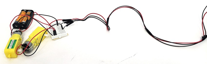
Figure 9. Wires bundled with electrical tape to avoid tangling. - Once your circuit is working, you are ready to build your robot's body! Refer back to the drawings you made in step 1. Do you need to change any part of your plan now that you have built the circuit? For example, are the wires long enough to put the motors, breadboard, and battery holder where you want them?
- Use craft materials to build your robot's body. Figure 10 shows a very simple example made from a piece of cardboard, but remember that you can use other materials or make a different design.
- Use tape or glue to attach the motors, breadboard, and battery holder to your robot's body. Remember that the motors should be parallel to each other on opposite sides of the body. Make sure the white shafts stick out to the sides so you can attach the wheels.
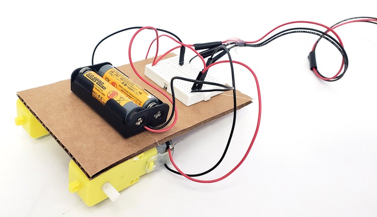
Figure 10. A simple robot body design made from a piece of cardboard. - Attach the wheels to the robot by pressing them firmly on to the white motor shafts. Note that since the robot only has two wheels, this will make one end drag around on the ground. If you want the robot to be level, you can use something, like a piece of cardboard tube, as a support to hold up one end of the robot (Figure 11). Make sure the supporting material is smooth and low-friction so it slides around on the floor easily.
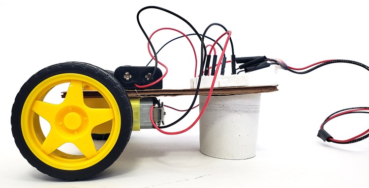
Figure 11. Side view of robot with wheels attached and a cardboard tube to keep the body level. - Test your robot.
- Put the robot down on the floor.
- Press and hold down one of the buttons. The robot should turn.
- Press and hold down the other button. The robot should turn the other way.
- Press and hold down both buttons. The robot should drive straight.
- Note: if a wheel spins backwards, reverse the red and black wires for the motor in the breadboard (unplug both wires, then plug the red wire in where the black wire was, and the black where in where the red wire was). That will make the motor spin the other way.
- Decorate your robot! Figure 12 shows an example.
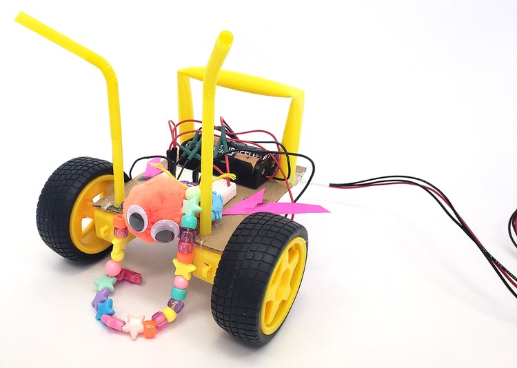
Figure 12. A completed, decorated robot. - Try driving your robot around. For example, try driving it in a square (alternate driving straight and making turns). Observe carefully and note if there are any problems with your robot.
- Are there any problems with your robot's circuit? For example, do any of the wires come loose? What happens if you accidentally tug on the remote too hard? Can you use glue or tape to hold the wires in place?
- Are there any problems with the robot's body? Is it sturdy enough? What happens if you accidentally crash into something? Can you reinforce any parts of the body that break?
- Are there any problems with your robot's decorations? Do they interfere with the wheels spinning? Would they be in the way if you needed to fix the circuit or replace the batteries?
- Based on your observations, see if you can make changes to improve your robot's design, and then test it again. This is called iteration and it is an important part of the engineering design process. Engineers do not always get things right on the first try, and that is OK! Keep testing and improving your robot until you are happy with it. For more ideas about how to continue or improve your robot, see the Make It Your Own section.
/-/https/www.sciencebuddies.org/cdn/Files/18501/5/steerable-robot-breadboard-diagram.png)
/-/https/www.sciencebuddies.org/cdn/Files/18502/5/wire-twist-connections.png)
/-/https/www.sciencebuddies.org/cdn/Files/18503/5/steerable-robot-breadboard-diagram-wrong.png)
/-/https/www.sciencebuddies.org/cdn/Files/18504/6/wires-bundled.jpg)
/-/https/www.sciencebuddies.org/cdn/Files/18505/6/robot-body.jpg)
/-/https/www.sciencebuddies.org/cdn/Files/18506/5/robot-body-side-view.jpg)
/-/https/www.sciencebuddies.org/cdn/Files/18507/5/steerable-robot-decorated.jpg)
Ask an Expert
Global Goals
The United Nations Sustainable Development Goals (UNSDGs) are a blueprint to achieve a better and more sustainable future for all.
/-/https/www.sciencebuddies.org/cdn/Files/19752/5/E-WEB-Goal-09.png)
Variations
- Can you make a four-wheeled or "all terrain" robot? Buy a second set of motors and wheels. Connect one motor in parallel to each motor already in your circuit (so each button will control two motors). Note that this many motors will require more current, so you may want to increase the size of your battery pack to 3xAA or 4xAA if your robot is too slow.
- If you have access to a soldering iron, you can make a more permanent version of your robot's circuit. Search for "protoboard" or "perfboard" on any electronics vendor's website and you will find a variety of options. Unlike solderless breadboards, which allow temporary, removable connections, these boards have holes that you can permanently solder wires to. This means it is harder to undo a mistake, but the connection will be much sturdier and wires will not fall out when you pull on the remote.
- Can you design a better handheld controller for your robot, instead of just using the mini breadboard? You might want to look at video game controllers for inspiration.
- For advanced students: can you build a robot that can also drive in reverse? You will need to include a part called an H-bridge in your circuit. See the Obstacle-Avoiding Robot project for more information.
- If you are ready for robots that include more advanced circuits or even programming, check out the Bluebot series of projects.
Careers
If you like this project, you might enjoy exploring these related careers:
/-/https/careerdiscovery.sciencebuddies.org/cdn/Files/1725/18/4161_Michelle_Easter_and_Curiousity_Clone.jpg)
/-/https/careerdiscovery.sciencebuddies.org/cdn/Files/1223/17/iStock-971549326.jpg)
/-/https/careerdiscovery.sciencebuddies.org/cdn/Files/1450/21/iStock-1227179796.jpg)

/-/https/img.youtube.com/vi/FMcbAiTfx7A/0.jpg)
/-/https/img.youtube.com/vi/Sfu1UUmF2jA/0.jpg)
/-/https/img.youtube.com/vi/U7XYzPfutBs/0.jpg)